EP0926465B1 - Dispositif de mesure de l'état de la surface avec une pointe et un moyen de soulèvement du détecteur - Google Patents
Dispositif de mesure de l'état de la surface avec une pointe et un moyen de soulèvement du détecteur Download PDFInfo
- Publication number
- EP0926465B1 EP0926465B1 EP98310342A EP98310342A EP0926465B1 EP 0926465 B1 EP0926465 B1 EP 0926465B1 EP 98310342 A EP98310342 A EP 98310342A EP 98310342 A EP98310342 A EP 98310342A EP 0926465 B1 EP0926465 B1 EP 0926465B1
- Authority
- EP
- European Patent Office
- Prior art keywords
- detector
- measuring device
- stylus
- driving mechanism
- surface property
- Prior art date
- Legal status (The legal status is an assumption and is not a legal conclusion. Google has not performed a legal analysis and makes no representation as to the accuracy of the status listed.)
- Expired - Lifetime
Links
- 230000007246 mechanism Effects 0.000 claims description 42
- 241001422033 Thestylus Species 0.000 description 26
- 238000005259 measurement Methods 0.000 description 20
- 230000003746 surface roughness Effects 0.000 description 13
- 238000010276 construction Methods 0.000 description 6
- 238000006073 displacement reaction Methods 0.000 description 6
- 230000008878 coupling Effects 0.000 description 2
- 238000010168 coupling process Methods 0.000 description 2
- 238000005859 coupling reaction Methods 0.000 description 2
- 238000010586 diagram Methods 0.000 description 2
- 230000009467 reduction Effects 0.000 description 2
- 230000001174 ascending effect Effects 0.000 description 1
- 238000000034 method Methods 0.000 description 1
- 230000000414 obstructive effect Effects 0.000 description 1
- 230000008569 process Effects 0.000 description 1
- 238000004439 roughness measurement Methods 0.000 description 1
- 239000000758 substrate Substances 0.000 description 1
Images


Classifications
-
- G—PHYSICS
- G01—MEASURING; TESTING
- G01B—MEASURING LENGTH, THICKNESS OR SIMILAR LINEAR DIMENSIONS; MEASURING ANGLES; MEASURING AREAS; MEASURING IRREGULARITIES OF SURFACES OR CONTOURS
- G01B7/00—Measuring arrangements characterised by the use of electric or magnetic techniques
- G01B7/34—Measuring arrangements characterised by the use of electric or magnetic techniques for measuring roughness or irregularity of surfaces
Definitions
- the present invention relates to a surface property measuring device comprising a detector having at a leading end thereof a stylus for measuring surface property, typically, surface roughness, and a skid, and a driving mechanism for causing the detector to advance and retreat along a surface to be measured, more particularly, to a surface property measuring device which is capable of protecting a nose, the stylus, and the skid which protrude from the detector, when arranging the measurement, such as setting the measuring device to an article to be measured, and removing the measuring device after the measurement.
- a surface roughness measuring device of applying a stylus on a surface to be measured, and measuring the surface roughness by detecting a surface roughness-direction-wise displacement of the stylus while advancing and retreating a detector including the stylus along the surface to be measured, to thereby convert the detected displacement into an electrical signal and then process the electrical signal in a predetermined manner.
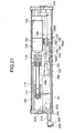
- a surface roughness measuring device comprising a sliding shaft 34 held on a bearing 33, which is disposed on a frame 32 of the driving mechanism, and sliding in an advancing and retreating direction (in the direction shown by the arrow A) of a detector 10, a driving-side connector 40 attached to the sliding shaft 34 through a moving block 36 and a leaf spring 38, a feed block 44 fixed to the sliding shaft 34 through a connecting portion 42 for causing the sliding shaft 34 to advance and retreat in the direction shown by the arrow A, a feed screw 46 engaged with the feed block 44, a reduction gear 50 connected to the feed screw 46 through a coupling 48, and a motor 52 for rotation-driving the reduction gear 50.
- reference numeral 14 designates a detector-side connector pin attached to a rear end (on the right-hand end of the drawing) of a case 12 of the detector 10 and engaged with the driving-side connector 40, 18 a stylus arm having a stylus 16, which moves up and down while following the surface to be measured, at a leading end thereof (on the left-hand end of the drawing) and swinging in the case 12 with a fulcrum (20) as a center, 20 a leaf spring shaped like a substantially L, constituting the fulcrum of the stylus arm 18, 22 an inductance type displacement detector disposed in the vicinity of a rear end of the stylus arm 18 for detecting an up-and-down movement of the rear end of the stylus lever 18, 24 a skid for absorbing minute irregularities in the vicinity of the stylus 16 to thereby obtain a stable measured value, and 26 a nose for protecting the stylus 16 and the stylus arm 18.
- reference numeral 70 designates a fulcrum of the arm 66, 72 a displacement detector for detecting a displacement of a rear end of the arm 66, 74 a friction-transmitting wheel for transmitting the rotation of the motor 60 in such a manner as to slip when a load exceeds a predetermined value.
- the applicant further proposes in Japanese Utility Model Publication (Kokoku) No. 63-10481 providing a stylus-protecting spring for urging a stylus arm by an urging force which overcomes an urging force of a measuring pressure applying spring in such a direction as that a stylus is received in a protecting case, and an electromagnet for absorbing the stylus-protecting spring due to the energization carried out in measurement, to thereby release the stylus arm from the urging force of the stylus-protecting spring.
- Kokoku Japanese Utility Model Publication
- Japanese Utility Model Publication (Kokoku) No. 63-10482 providing receiving means which jointly uses a permanent magnet and a pair of coils, when measuring, causes (permanent) magnet piece-side end faces of the coils to be instantaneously excited to one of an N-pole and an S-pole, thereby causing the magnet piece to be separated from a stylus arm, whereas, when not measuring, causes the (permanent) magnet piece-side end faces of the coils to be instantaneously excited to the other of the N-pole and the S-pole, thereby causing the magnet piece to press the stylus arm in an opposite direction to the urging direction of the measuring pressure applying spring.
- any one of the devices requires an independent power source such as a motor, and an electromagnet, and hence has problems that its mechanism is complicated, and the reliability of the operation is apt to come into question.
- the present invention has been made in order to solve the above-mentioned conventional problems. It is therefore an object of the present invention to protect a surface to be measured, a nose, a stylus, and a skid which protrudes from a detector when not measuring and when preparing the measurement, by a simple construction and without requiring an independent power source.
- the invention claimed in claim 1 provides a surface property measuring device comprising a detector having a stylus for measuring surface property; a skid at a leading end thereof; a driving mechanism for causing said detector to advance and retract along a surface to be measured, wherein said device comprises a detector-lifting means which lifts at least said leading end of said detector to separate said skid and said stylus from said surface to be measured as said detector is fully retracted by the driving mechanism.
- the surface to be measured is not damaged by the stylus permanently contacting to the surface to be measured.
- the nose, the stylus, and the skid of the detector are prevented from carelessly colliding with the article to be measured, which prevents the damages of the nose, the stylus, and the skid, and also the article to be measured. Furthermore, even when the measuring device is dropped by mistake, the nose, the skid, and the stylus of the detector can be protected.
- An embodiment claimed in claim 2 provides a surface property measuring device in which the detector-lifting means comprises a detector-lifting plate which engages with a part of a member moving as the detector advances and retreats, to thereby lift the detector.
- An embodiment claimed in claim 3 provides a surface property measuring device in which the detector is detachable from the driving mechanism by a connector, and an angle-like protrusion engaging with the detector-lifting plate is disposed outside a driving-side housing of the connector.
- An embodiment claimed in claim 4 provides a surface property measuring device in which the position of the detector-lifting plate is adjustable in an advancing and retreating direction of the detector.
- a surface property measuring device comprising an electric equipment section for housing the driving mechanism, wherein all the detector is housed in the electrical equipment section when the detector retracts.
- the invention claimed in claim 6 provides a surface property measuring device in which all the detector is housed in the driving mechanism when the detector retracts.
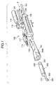
- a driving mechanism 100 comprises a main shaft 104 and a sub shaft 106 which are fixed to a frame 102 of the driving mechanism 100, a slide block 108, which is shaped like a substantially O elongated in an advancing and retreating direction (in the direction shown by the arrow A) of a detector, sliding on the shafts 104, 106, the main shaft 104 being inserted through at two of a fore and a rear location thereof, an interlinking rod 110 and a feed nut 112 causing the slide block 108 to advance and retreat along the shafts 104, 106, a feed screw 114 screwed with the feed nut 112, and a gear motor 118 for rotating the feed screw 114 through a flexible coupling 116.
- a detector mount 108A is formed on a rear end of the slide block 108, and to a lower side of the slide block 108 are fixed by bolts 122 both of a leaf spring 152 attached to a rear end of a connector housing 150 for containing a detector 200, for providing a skid pressure, and a shaft supporting plate 120 for pressing a lower surface of the sub shaft 106. Further, a leaf spring 126, on which a sliding plate 124 for pressing an upper side of the sub shaft 106, is fixed on an upper side of the detector mount 108A through bolts 128.
- an L-like detector-lifting plate 140 shown in Fig. 9, is fixed to the frame 102 by bolts 142.
- the detector-lifting plate 140 is so adapted that an engaging portion 140A thereof engages with an angle-like protrusion 150A formed on an outer side face of the connector housing 150 at a retracting location of the detector 200 in the vicinity of its retreating limit position.
- the protrusion 150A of the connector housing 150 runs on to the engaging portion 140A of the detector-lifting plate 140, thereby causing the connector housing 150 to be lifted with a leaf spring 152 as a center, which causes the stylus 202 and the skid 204 disposed at a leading end of the detector 200 to be separated from the surface to be measured, and hence prevents them from protruding downward from a bottom surface of the driving mechanism 100.
- a bolthole 14B for fixing the detector-lifting plate 140 is, as shown in Fig. 9, elongated in an advancing and retreating direction of the detector 200. So, adjusting the fixing position of the detector-lifting plate 140 enables such a location as that a head of the detector 200 starts ascending to be adjusted, which prevents the head of the detector 200 from colliding with the driving mechanism, the electrical equipment section, and a ceiling portion of an inlet for the detector when the detector retracts for the head to thereby ascend.
- reference numeral 101 designates a case of a driving mechanism 130; a switch pin uprightly planted on the slide block 108; 132 and 143 a fore and a rear end switch engaging with the switch pin 130 to stop or reverse the gear motor 118; 154 a driving-side connector contained in the connector housing 150; 206 a detector-side connector pin inserted into the driving-side connector 154; 208 a connector housing of the detector, and 210 a nose of the same.
- the driving mechanism 100 can be contained in an electrical equipment section 300, as shown in Figs. 10 to 12 described later. On a rear end of the driving mechanism 100 is disposed an electrical equipment-side connector 136 electrically connected to the electrical equipment section 300, and a portion between the electrical equipment-side connector 136 and the driving-side connector 154 is wired by a thin flexible printed circuit substrate (FPC) 138, having a thickness of, e.g. about 0.2 mm, through the connector housing 150.
- FPC thin flexible printed circuit substrate
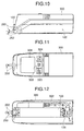
- the electrical equipment section 300 mainly comprises, as shown in Fig. 10 (front view), Fig. 11 (plan view), Fig. 12 (bottom view), and Fig. 13 (block diagram), a signal processing circuit 304 for processing a signal, which is obtained from the detector 200 contained in the driving mechanism 100, through a cable 302 connected with the electric equipment-side connector 136, a measuring circuit 306 for obtaining a surface roughness corresponding to various kinds of parameters based on the signal from the signal processing circuit 304, a digital display 308 for displaying the measured value obtained by the measuring circuit 306, a driving circuit 310 for driving the gear motor 118 in the driving mechanism 100 through the cable 302, a control circuit 312 for controlling the driving circuit 310, the measuring circuit 306, and the digital display 308, and an electric power circuit 314 for supplying an electric power to the above respective circuit.
- a signal processing circuit 304 for processing a signal, which is obtained from the detector 200 contained in the driving mechanism 100, through a cable 302 connected with the electric equipment-side connector 136
- the solid line in the drawing shows the position of a leading end of the detector 200 exposed when measuring, and the one dot chain line shows the position of the leading end of the detector 200 exposed when it is housed in the electrical equipment section 300.
- reference numeral 320 designates an electric power switch, 322 a start switch, and 324 a parameter-selecting switch.
- a nosepiece 160 for protecting the leading end of the detector 200, etc. is disposed on a front end of the driving mechanism 100.
- the nosepiece 160 includes a nosepiece 160A for cylinder measurement, which is concave in its front bottom shape as shown in Fig. 15, and a nosepiece 160B for plane measurement, which is convex in its front bottom shape as shown in Fig. 16.
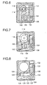
- the nosepiece 160A for cylinder measurement is attached to the driving mechanism 100 by bolts 162 as shown in Fig. 17 (an exploded perspective view) and Fig. 18 (a perspective view in the nosepiece-attached state), and the nosepiece 160B for plane measurement as shown in Fig. 19 (an exploded perspective view) and Fig. 20 (a perspective view in the nosepiece-attached state).
- a nosepiece 160 makes it difficult for the leading end of the detector 200, etc., to be affected by an external force from except the surface to be measured, when measuring, thereby results in sufficient protection of the detector 200; however, the leading end (the skid 204 and the stylus 202) of the detector 200, as shown in Fig. 14, protrudes from the surface to be measured, when transporting, thereby possibly providing damages without protection.
- the leading end of the detector 200 from the surface to be measured and hence retracting it prevents the leading end of the detector 200 from protruding from the surface to be measured, thereby causing the leading end of the detector 200 to be received in the nosepiece 160, which realizes sure protection also even when transporting the detector, etc.
- the driving mechanism 100 When measuring, according to the object to be measured, it is, as shown in Figs. 10 to 12, selected whether the driving mechanism 100 is used in such a manner that it is housed in the electrical equipment section 300, or the driving mechanism 100 is independently used in such a manner that it is separated from the electrical equipment section 300. For example, when measuring an inner surface of a small hole, the measurement is made with the driving mechanism 100 removed because the electric equipment section 300 is obstructive, and with the driving mechanism 100 united to the electric equipment section 300 in the other cases.
- the stylus 202 of the detector 200 is contacted to a surface to be measured, the electric power switch 320 is turned on, and the start switch 322 is pressed. Then, the control circuit 312 causes the gear motor 118 to rotate through the driving circuit 310. When rotation of the gear motor 118 causes the feed screw 114 to rotate, the slide block 108 is moved in an axial direction of the feed screw 114; therefore, the stylus 202 of the detector 200 is displaced up and down according to the surface roughness of an article to be measured.
- the displacement of the stylus 202 is converted into an electrical signal by the detector 200, then transmitted to the signal processing circuit 304 through a cable 302. Thereafter, the processed signal is transmitted to the measuring circuit 306.
- the measuring circuit 306 obtains the surface roughness based on the signal transmitted from the signal processing circuit 304 according to the parameters instructed from the control circuit 312, and let it displayed on the digital display 308.
- the connector housing 150 and the detector 200 connected thereto are retreated deep to the utmost in the driving mechanism 100 by an instruction of retraction.
- the protrusion 150A disposed outside the connector housing 150 runs on to the engaging portion 140A of the detector-lifting plate 140, thereby causing the leading end of the detector 200 to be lifted with the leaf spring 152 as a center, which causes the stylus 202 and the skid 204 to be separated from the surface to be measured. This prevent the stylus permanently contacting to the surface to be measured, thereby preventing the surface of an article to be measured from being damaged.
- the nose 210, the stylus 202 and the skid 204 are prevented from carelessly colliding with the article to be measured, which prevents these components, and the article to be measured, from being damaged.
- the detector 200 is retreated deep to the utmost in the driving mechanism 100, and then all the detector is received in the electrical equipment section 300 when it is at a retracted position, which enables the nose, the skid, and the stylus of the detector to be protected even if the measuring device is carelessly collided with a certain object, or is dropped.
- This embodiment has such a receiving construction as that all the detector is received not in the driving mechanism, but in the electric equipment section 300, which prevents the driving mechanism from becoming large-sized.
- the case 101 of the driving mechanism 100 extends forward, so that the stylus 202 and the skid 204 of the leading end of the detector 200 are completely received in the driving mechanism 100 when they are at a retracted position.
- the nose 210, the stylus 202, and the skid 204 of the detector 200 can be protected even if the driving mechanism 100 is independently transported and carelessly collided with a certain object, or is dropped.
- lifting the detector 200 with the leaf spring 152 as a center, by a combination of the detector-lifting plate 140 and the angle-like protrusion 150A formed outside the connector housing 150 makes the construction simple. Moreover, the construction of lifting the detector when retracting the detector is not limited to the above.
- the invention is applied to the stationary portable surface roughness-measuring device
- the application of the invention is not limited thereto, and hence the invention can be applied to, for example, contour measuring devices, and surface roughness proves used for three-dimensional coordinates measuring machines.
Landscapes
- Physics & Mathematics (AREA)
- General Physics & Mathematics (AREA)
- A Measuring Device Byusing Mechanical Method (AREA)
- Length Measuring Devices With Unspecified Measuring Means (AREA)
Claims (6)
- Dispositif de mesure de l'état d'une surface comprenant un détecteur (200) muni d'une pointe (202) pour mesurer l'état de la surface, d'un patin (204) à son extrémité avant, et d'un mécanisme de commande (100) pour permettre audit détecteur (200) d'avancer et de reculer le long de la surface à mesurer,
ledit dispositif comprenant un moyen de soulèvement du détecteur (140) qui soulève au moins ladite extrémité avant dudit détecteur (200) pour séparer ledit patin (204) et ladite pointe (202) de ladite surface à mesurer lorsque ledit détecteur (200) est mis en position entièrement rétractée par le mécanisme de commande. - Dispositif de mesure de l'état de la surface selon la revendication 1, dans lequel ledit moyen de soulèvement du détecteur comprend une plaque de soulèvement du détecteur (140) qui s'engrène avec une partie d'un élément (150) qui se déplace lorsque ledit détecteur (200) avance et recule, pour soulever ainsi ledit détecteur (200).
- Dispositif de mesure de l'état de la surface selon la revendication 2, dans lequel ledit détecteur (200) est détachable dudit mécanisme de commande (100) grâce à des connecteurs (154 et 208), et une saillie en forme de coin (150A) s'engrenant avec ladite plaque de soulèvement du détecteur (140) est disposée en dehors d'un boítier du côté commande (150) dudit connecteur (154).
- Dispositif de mesure de l'état de la surface selon l'une des revendications 1 ou 2, dans lequel la position de ladite plaque de soulèvement du détecteur (140) est réglable dans les directions d'avance et de recul dudit détecteur (200).
- Dispositif de mesure de l'état de la surface selon l'une des revendications 1 à 4, comprenant en outre une section d'équipement électrique (300) pour abriter ledit mécanisme de commande (100), la totalité dudit détecteur (200) étant abrité dans ladite section d'équipement électrique (300) lorsque ledit détecteur (200) se rétracte.
- Dispositif de mesure de l'état de la surface selon l'une des revendications 1 à 4, dans lequel la totalité dudit détecteur (200) est abrité dans ledit mécanisme de commande (100) lorsque ledit détecteur (200) se rétracte.
Applications Claiming Priority (2)
| Application Number | Priority Date | Filing Date | Title |
|---|---|---|---|
| JP35888597A JP3640201B2 (ja) | 1997-12-26 | 1997-12-26 | 表面性状測定機 |
| JP35888597 | 1997-12-26 |
Publications (3)
| Publication Number | Publication Date |
|---|---|
| EP0926465A2 EP0926465A2 (fr) | 1999-06-30 |
| EP0926465A3 EP0926465A3 (fr) | 1999-10-13 |
| EP0926465B1 true EP0926465B1 (fr) | 2003-04-23 |
Family
ID=18461608
Family Applications (1)
| Application Number | Title | Priority Date | Filing Date |
|---|---|---|---|
| EP98310342A Expired - Lifetime EP0926465B1 (fr) | 1997-12-26 | 1998-12-16 | Dispositif de mesure de l'état de la surface avec une pointe et un moyen de soulèvement du détecteur |
Country Status (4)
| Country | Link |
|---|---|
| US (1) | US6164124A (fr) |
| EP (1) | EP0926465B1 (fr) |
| JP (1) | JP3640201B2 (fr) |
| DE (1) | DE69813751T2 (fr) |
Families Citing this family (12)
| Publication number | Priority date | Publication date | Assignee | Title |
|---|---|---|---|---|
| JP3373465B2 (ja) | 1999-11-01 | 2003-02-04 | 株式会社ミツトヨ | 表面性状測定機 |
| JP3474504B2 (ja) * | 1999-11-01 | 2003-12-08 | 株式会社ミツトヨ | 駆動装置 |
| US6954987B2 (en) * | 2003-05-22 | 2005-10-18 | Powerwave Technologies, Inc. | Method of interconnecting a circuit board to a substrate |
| DE102005035786B3 (de) * | 2005-07-27 | 2007-01-04 | Carl Mahr Holding Gmbh | Rauheitstaster |
| JP5331645B2 (ja) * | 2009-10-13 | 2013-10-30 | 株式会社ミツトヨ | 検出器、及び測定機 |
| US8413492B1 (en) | 2009-10-23 | 2013-04-09 | Honda Motor Co., Ltd. | Cylinder sleeve surface measurement assembly |
| JP6104557B2 (ja) | 2012-10-18 | 2017-03-29 | 株式会社ミツトヨ | 表面粗さ測定ユニット、三次元測定装置 |
| JP5846462B1 (ja) * | 2014-10-28 | 2016-01-20 | 株式会社東京精密 | 形状測定装置 |
| WO2019155845A1 (fr) * | 2018-02-09 | 2019-08-15 | コニカミノルタ株式会社 | Appareil de profilage |
| KR101888466B1 (ko) * | 2018-02-12 | 2018-08-16 | 황재은 | 형상측정기 |
| GB2582375B (en) * | 2019-03-22 | 2022-07-06 | Taylor Hobson Ltd | Metrological apparatus and method of manufacture |
| JP7448323B2 (ja) | 2019-09-06 | 2024-03-12 | 株式会社ミツトヨ | 粗さ測定機 |
Family Cites Families (9)
| Publication number | Priority date | Publication date | Assignee | Title |
|---|---|---|---|---|
| DE2654421C2 (de) * | 1976-12-01 | 1985-06-27 | Hommelwerke GmbH, 7730 Villingen-Schwenningen | Meßvorrichtung zur Messung der Oberflächenbeschaffenheit eines Werkstücks |
| JPS5876107A (ja) * | 1981-10-31 | 1983-05-09 | Mitsubishi Heavy Ind Ltd | 軟泥沈降処理装置 |
| GB2192062B (en) * | 1986-06-27 | 1990-02-28 | Rank Taylor Hobson Ltd | Metrological apparatus |
| JPS6310482A (ja) * | 1986-06-28 | 1988-01-18 | 富士通株式会社 | コネクタの接続方法 |
| JPS6310481A (ja) * | 1986-06-30 | 1988-01-18 | ヒロセ電機株式会社 | コンデンサ入り電気コネクタ |
| JP2675179B2 (ja) * | 1990-06-29 | 1997-11-12 | 浜松ホトニクス株式会社 | 偏光子 |
| DE4129687C2 (de) * | 1991-09-08 | 2002-11-14 | Helmut Fischer Gmbh & Co | Vorrichtung zur Messung der Dicke dünner Schichten |
| JPH0575606A (ja) * | 1991-09-17 | 1993-03-26 | Nec Corp | 相手先アドレス集約登録方式 |
| GB2281779B (en) * | 1993-09-14 | 1997-04-23 | Rank Taylor Hobson Ltd | Metrological instrument |
-
1997
- 1997-12-26 JP JP35888597A patent/JP3640201B2/ja not_active Expired - Fee Related
-
1998
- 1998-12-15 US US09/210,933 patent/US6164124A/en not_active Expired - Lifetime
- 1998-12-16 DE DE69813751T patent/DE69813751T2/de not_active Expired - Lifetime
- 1998-12-16 EP EP98310342A patent/EP0926465B1/fr not_active Expired - Lifetime
Also Published As
| Publication number | Publication date |
|---|---|
| DE69813751D1 (de) | 2003-05-28 |
| JPH11190621A (ja) | 1999-07-13 |
| US6164124A (en) | 2000-12-26 |
| EP0926465A3 (fr) | 1999-10-13 |
| DE69813751T2 (de) | 2003-10-16 |
| EP0926465A2 (fr) | 1999-06-30 |
| JP3640201B2 (ja) | 2005-04-20 |
Similar Documents
| Publication | Publication Date | Title |
|---|---|---|
| EP0926465B1 (fr) | Dispositif de mesure de l'état de la surface avec une pointe et un moyen de soulèvement du détecteur | |
| EP2111951B1 (fr) | Outil de serrage et système de gestion d'outil de serrage | |
| CN113370119B (zh) | 一种拆解治具 | |
| EP0926464A2 (fr) | Dispositif de mesure de l'état de la surface avec une pointe et un bloc de glissement long | |
| CA2509897A1 (fr) | Protecteur d'aiguilles medicales | |
| EP1017155A4 (fr) | Dispositif de positionnement, unite d'entrainement et aligneur equipe d'un tel dispositif | |
| EP0221802B1 (fr) | Porte-outil de sécurité pour machine-outil | |
| CN108931225B (zh) | 表面性状测量装置 | |
| US4738033A (en) | Rapid change holder for probe pins | |
| US6615879B2 (en) | Binding tool | |
| CN114475704A (zh) | 一种电动转辙机 | |
| EP0903690A3 (fr) | Dispositif connecteur pour une carte à circuits intégrés | |
| US4055070A (en) | Gage stop assembly | |
| EP0940603A3 (fr) | Mecanisme d'engrenages et rétracteur de sangle | |
| WO2016145336A1 (fr) | Outil électrique doté d'une plaque de couplage protégé | |
| US4460195A (en) | Automatic clamping and release mechanism | |
| ATE263656T1 (de) | Elektrische antriebsspindel | |
| JP5177376B2 (ja) | マーキング機能付きトルクレンチ | |
| KR880010649A (ko) | 전기 또는 전자부품 조작장치 | |
| EP0912859B1 (fr) | Dispositif de securite pour machine d'atelier | |
| CA1223018A (fr) | Mecanisme de serrage | |
| GB2351725B (en) | Mounting assembly | |
| US4996868A (en) | Calibration device for banding tools | |
| JP3266400B2 (ja) | 墜落防止器 | |
| JP4200577B2 (ja) | 円筒研削盤のハイポイドピニオンワーク用回転駆動装置 |
Legal Events
| Date | Code | Title | Description |
|---|---|---|---|
| PUAI | Public reference made under article 153(3) epc to a published international application that has entered the european phase |
Free format text: ORIGINAL CODE: 0009012 |
|
| AK | Designated contracting states |
Kind code of ref document: A2 Designated state(s): DE FR GB |
|
| AX | Request for extension of the european patent |
Free format text: AL;LT;LV;MK;RO;SI |
|
| PUAL | Search report despatched |
Free format text: ORIGINAL CODE: 0009013 |
|
| AK | Designated contracting states |
Kind code of ref document: A3 Designated state(s): AT BE CH CY DE DK ES FI FR GB GR IE IT LI LU MC NL PT SE |
|
| AX | Request for extension of the european patent |
Free format text: AL;LT;LV;MK;RO;SI |
|
| 17P | Request for examination filed |
Effective date: 20000321 |
|
| AKX | Designation fees paid |
Free format text: DE FR GB |
|
| 17Q | First examination report despatched |
Effective date: 20000615 |
|
| GRAH | Despatch of communication of intention to grant a patent |
Free format text: ORIGINAL CODE: EPIDOS IGRA |
|
| GRAH | Despatch of communication of intention to grant a patent |
Free format text: ORIGINAL CODE: EPIDOS IGRA |
|
| GRAA | (expected) grant |
Free format text: ORIGINAL CODE: 0009210 |
|
| AK | Designated contracting states |
Designated state(s): DE FR GB |
|
| REG | Reference to a national code |
Ref country code: GB Ref legal event code: FG4D |
|
| REF | Corresponds to: |
Ref document number: 69813751 Country of ref document: DE Date of ref document: 20030528 Kind code of ref document: P |
|
| ET | Fr: translation filed | ||
| PLBE | No opposition filed within time limit |
Free format text: ORIGINAL CODE: 0009261 |
|
| STAA | Information on the status of an ep patent application or granted ep patent |
Free format text: STATUS: NO OPPOSITION FILED WITHIN TIME LIMIT |
|
| 26N | No opposition filed |
Effective date: 20040126 |
|
| REG | Reference to a national code |
Ref country code: FR Ref legal event code: PLFP Year of fee payment: 18 |
|
| REG | Reference to a national code |
Ref country code: FR Ref legal event code: PLFP Year of fee payment: 19 |
|
| REG | Reference to a national code |
Ref country code: FR Ref legal event code: PLFP Year of fee payment: 20 |
|
| PGFP | Annual fee paid to national office [announced via postgrant information from national office to epo] |
Ref country code: FR Payment date: 20171221 Year of fee payment: 20 Ref country code: DE Payment date: 20171211 Year of fee payment: 20 |
|
| PGFP | Annual fee paid to national office [announced via postgrant information from national office to epo] |
Ref country code: GB Payment date: 20171221 Year of fee payment: 20 |
|
| REG | Reference to a national code |
Ref country code: DE Ref legal event code: R071 Ref document number: 69813751 Country of ref document: DE |
|
| REG | Reference to a national code |
Ref country code: GB Ref legal event code: PE20 Expiry date: 20181215 |
|
| PG25 | Lapsed in a contracting state [announced via postgrant information from national office to epo] |
Ref country code: GB Free format text: LAPSE BECAUSE OF EXPIRATION OF PROTECTION Effective date: 20181215 |