EP0926525A2 - Table de positionnement - Google Patents
Table de positionnement Download PDFInfo
- Publication number
- EP0926525A2 EP0926525A2 EP98121625A EP98121625A EP0926525A2 EP 0926525 A2 EP0926525 A2 EP 0926525A2 EP 98121625 A EP98121625 A EP 98121625A EP 98121625 A EP98121625 A EP 98121625A EP 0926525 A2 EP0926525 A2 EP 0926525A2
- Authority
- EP
- European Patent Office
- Prior art keywords
- positioning table
- adhesive
- table according
- cover plate
- support body
- Prior art date
- Legal status (The legal status is an assumption and is not a legal conclusion. Google has not performed a legal analysis and makes no representation as to the accuracy of the status listed.)
- Granted
Links
Images


Classifications
-
- B—PERFORMING OPERATIONS; TRANSPORTING
- B25—HAND TOOLS; PORTABLE POWER-DRIVEN TOOLS; MANIPULATORS
- B25H—WORKSHOP EQUIPMENT, e.g. FOR MARKING-OUT WORK; STORAGE MEANS FOR WORKSHOPS
- B25H1/00—Work benches; Portable stands or supports for positioning portable tools or work to be operated on thereby
- B25H1/02—Work benches; Portable stands or supports for positioning portable tools or work to be operated on thereby of table type
-
- G—PHYSICS
- G02—OPTICS
- G02B—OPTICAL ELEMENTS, SYSTEMS OR APPARATUS
- G02B21/00—Microscopes
- G02B21/24—Base structure
- G02B21/26—Stages; Adjusting means therefor
-
- G—PHYSICS
- G02—OPTICS
- G02B—OPTICAL ELEMENTS, SYSTEMS OR APPARATUS
- G02B7/00—Mountings, adjusting means, or light-tight connections, for optical elements
-
- G—PHYSICS
- G12—INSTRUMENT DETAILS
- G12B—CONSTRUCTIONAL DETAILS OF INSTRUMENTS, OR COMPARABLE DETAILS OF OTHER APPARATUS, NOT OTHERWISE PROVIDED FOR
- G12B5/00—Adjusting position or attitude, e.g. level, of instruments or other apparatus, or of parts thereof; Compensating for the effects of tilting or acceleration, e.g. for optical apparatus
Definitions
- the invention relates to a positioning table with at least a support body made of at least a first material, the one Has a large number of recesses.
- Positioning table after manufacture (preferably on mirrored surfaces, on measuring surfaces or on contact surfaces for other components) have only minimal deformations, whereby the allowed deformation range in the nanometer range lies.
- positioning table not only is the size and weight of the positioning table but especially its shape and its Vibration behavior relevant (especially inner edges). These positioning tables are preferably used in Areas in which nanometer differences are relevant quantities (e.g. microscopy, astronomy, etc.).
- DE 37 11 466 describes a device for connecting known at least two bodies, in which by means of a Tie rods are connected to each other without thermal Coercive forces occur.
- This device has the disadvantage that the two bodies are reworked after the connection must, because the tie rod at the connecting surfaces strong forces generated. But the connection is very stable.
- DE 39 34 546 describes a device for adhesive Connection of two bodies known by means of an intermediate piece, but with the spacers up to the surfaces of the two Bodies are guided and the surface in their area is not can be used.
- positioning table Due to the small deformations of the positioning table it is particularly suitable for gluing Use in optical devices with small wavelengths work. Thereby be under a positioning table movable table meant which movements on the X and / or the Y axis and sometimes the Z axis can perform. Such positioning tables are particularly in UV microscopes or in devices whose main wavelength in the UV range is below 400 nm.
- the positioning table (101) shown in FIGS. 1 and 2 consists essentially of a support body (102) with a cover plate (3) attached to it. Both bodies (101, 102) are made of the same material and consist of the same Material (whereby as materials in particular silicates, Ceramics (e.g. Zerodur) and special metals (e.g. Invar) low thermal expansion coefficient are suitable).
- the support body (102) has a lightweight structure, so that Table (101) has the greatest possible dynamic and special exposed to strong positive and negative acceleration forces can be. To a high despite the lightweight construction Stiffness of the positioning table (101) especially in the The webs are the X and Y axes and are to be obtained transversely to them (104) between the nodes (105) and the support points (106) in oriented to these preferred directions.
- nodes (105) and bases (106) Prepared glue points (107) at which the cover plate (103) is attached to the support body (102) by gluing.
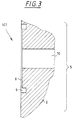
- the shape of these glue points (107) is shown in the figure 3 explained again.
- the adhesive points (107) between the support body (102) and the cover plate (103) can specifically the bending stiffness of the positioning table (101) can be changed that it foreseeably deforms when accelerating.
- the highest possible bending stiffness must be maintained.
- the lightweight structure By distributing the glue points (107) on the structure the lightweight structure, its dimensioning (i.e. in particular Size of the adhesive circle diameter) and the attachment of Compensating bodies (108) then make a fine adjustment of the Deformation or vibration behavior of the positioning table (101) to that of a compensating electronics (in the figure not shown) predetermined correction values.
- correction values cannot be stored in tables or even be calculated, you want a correction in real time to reach. They are specified by the compensating electronics and the positioning table (101) must be in its deformation or Vibration behavior can be adapted to it.
- the adhesive points (107) lie on the knot (105) completely inside the knot surfaces.
- the adhesive is through circular holes (whose diameter is preferably about 1 to 2 mm) exactly in the center of the circular adhesive points (107) fed to this and flows in the very narrow adhesive gap (with a diameter of preferably approx. 6 mm) of the adhesive point (107) due to the capillary action.
- the undercut is made by an undercut around the adhesive gap Adhesive prevented the adhesive gap of the adhesive point (107) from closing leave.
- FIG. 3 shows one of the inner gluing points (5; 107 from Figure 2) on a node (105) shown in detail.
- the corresponding glue points (107) on the webs (104) and the bases (106) of the lightweight structure are corresponding designed, the pressure equalization channel of one the spaces up to the undercut are normally eliminated can.
- An adhesive point (5) consists of a flat surface (4) a counter surface (3) in which all needed for gluing Cutouts are incorporated.
- These recesses are in particular a flat circular one Adhesive pad (7) with a defined adhesive gap (8), which of a larger circular free cut (9) for limitation of the adhesive gap (8) is surrounded. Through this free cut (9) can the adhesive, which is in the adhesive gap (8) through Capillary forces spread to the area of this adhesive gap (8) can be limited.
- a circular cylindrical channel (10) ends Application of the adhesive under positive pressure (preferably in Range between 1 and 5 bar, especially in the range between 3 and 4 bar).
- the free cut (9) is included rectangular channel (11) for degassing the at Curing of the resulting gases.
- This glue insertion channel (10) should be as short as possible be so that the required overpressure when introducing the Glue does not have to be too high. You can also create by an underpressure on the channel (11) the required overpressure on other channel (10) can be reduced.
- the free cut (9) should be 2 mm larger Have a diameter and be as thick as 0.5 mm.
- the Volume ratio of glue point (5) to free cut (9) is then around 1: 4, whereby the value does not fall below 1: 3 should be.
- the free cut (9) in this example is around 69% of the connecting surface (3, 4) enclosed because the degassing channel (11) in the free cut (9) ends.
- the degassing channel (11) himself is again until he leaves the two Bodies (1, 2) on both sides of the connecting surface (3, 4) enclosed.
- the rectangular channel (11) for degassing during curing The gases produced by the adhesive should double Have the width of the free cut (9) and be just as high. At its dimensioning must also take its length into account to ensure good degassing. He can be smaller be selected if the glue point (5) is close to the edge of the two bodies to be connected (1, 2) is arranged and must be chosen larger if the glue point (5) continues in the Inside of the two bodies (1, 2) is located.
- the circular cylindrical channel (10) for introducing the In the example shown here, Klebers has a radius of a quarter of the radius of the adhesive pad (7) (its Dimensioning also depending on the viscosity of the glue used) and should be as short as possible be.
- one or both of them can be used opposite surfaces of the adhesive pad (7) slightly roughened be. Whether this makes sense also depends on the viscosity of the used adhesive and the adhesive gap thickness or width, since the glue the whole adhesive pad (7) up to the free cut (9) should fill out.
- UV-curing adhesive it can make sense be the walls of the degassing channel (11, 11 ') and the free cut (9) at least partially mirrored in order by the Degassing channel (11, 11 ') additionally UV light on the adhesive pad (7) to bring.
- the channel (10) it is possible to introduce the channel (10) to dispense with the glue if you take a glue which only after external application (e.g. Heating, exposure to UV light, etc.) curing, possibly with an increase in the volume of the adhesive.
- the correct gluing process is then triggered with a time delay.
- the amount of adhesive used is very critical.
- the adhesive pad (7) within the connecting surface (3, 4) important.
- Particularly advantageous is also the flat degassing channel (11, 11 ') (which ensures good degassing) and the round channel (10) for the introduction of the adhesive (which is the same as the introduction of the adhesive provides the least possible resistance).
- the round adhesive pad (7) with a channel opening in the middle ensures a clean flow of the adhesive as well as one low-stress adhesive point.
- To minimize the deformation of the bodies to be joined are preferably in To place the height of the thrust center.
- the recesses for performing the bonding are in the The above example is only incorporated on one of the contact surfaces, since this is easier in terms of production technology. Of course some of the recesses could also be on the opposite Contact surface to be incorporated, but this is Adjustment problems would result.
- the transition between the second body (2) and the first Body (1) i.e. the inner edge
- the transition between the second body (2) and the first Body (1) i.e. the inner edge
- the body to be manufactured consists of two separate ones Bodies (1, 2), which are assembled into a single part become.
- Bodies (1, 2) On the joining surfaces (connecting surfaces) (3, 4) are located in particular in Figures 3 to 5 described gluing points (marked there with 5).
- the way resulting body (1, 2) is characterized by a very high Accurate shape with high resilience at the same time Spurts out.
- the body (1, 2) described above is the Support plate (1) for an X-Y-Z positioning table, which in Microscopes are used, which radiation in the UV range use to check the parts to be inspected.
- Such Positioning tables with their support plates (1) must be in the be dimensionally stable and at the same time high Have firmness, what rapid movements of the table especially when the control tasks are automated allowed.
- Adhesives that have the least possible shrinkage and which is a secure bond with the material of the to be connected Enable body.
- Silicate and ceramics include epoxy glue a shrinkage of less than 3% or less than 0.6%.
- the glue spots in the interface between the two bodies to be connected not only provides a secure Connecting the two bodies to be connected with each other, especially with strong accelerations or their change, but also enables an adjustment of the vibration behavior of the connected body. So your holding power must especially only become fully effective when the connecting bodies at their connecting surfaces from each other want to solve. This can vary depending on the geometry of the connected Body and the position of the connecting surfaces relative to the or the acceleration directions take place at different speeds.
- the Free cut also in one body and the recess for Generation of the adhesive gap in the opposite body be formed.
- the adhesive feed channel could also be through the other of the bodies to be joined bring up the adhesive gap and the ventilation channel inside the body, far be arranged away from the connecting surfaces.
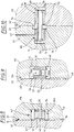
- connection between two bodies described below (30, 31) uses a voltage reducing element (37) (which can also be called compensation body), which is inserted between two bonds and which the through the shrinkage of the adhesive caused forces in the form of Absorbs tension.
- the adhesive bond thus obtained causes significantly less deformation of the precision-fitted Bodies (30, 31) than in the prior art known connection techniques.
- the physical background for the deformation caused by adhesive bonding in the joined bodies (30, 31) is essentially due to the shrinkage of the adhesive.
- F / A E * ⁇ with the force F, the adhesive surface A and the modulus of elasticity
- this body (37) which one between two adhesive points in a cavity (34) between the body to be glued (30, 31) is introduced, the Select the cross-sectional area and / or the modulus of elasticity.
- the bodies (30, 31) to be connected preferably consist of the same material (because of the coefficient of thermal expansion e.g. Silicate, ceramic or Invar) and own each have a connecting surface (32, 33) on which they to be glued together.
- a cavity open to the connecting surface (33) (34) (in the desired shape, e.g. rectangular or round cylinders) generated in which two channels (35, 36) end.
- a compensating element is placed on the bottom of this cavity (34) (37) with a first adhesive gap (44) glued in such a way that between the compensating element (37) and the side walls (39a, 39b) of the cavity (34) surrounding an air gap (40, 41) remains.
- a first adhesive gap (44) glued in such a way that between the compensating element (37) and the side walls (39a, 39b) of the cavity (34) surrounding an air gap (40, 41) remains.
- the compensating element (37) in the cavity (34) is glued in, through the body (31) and through the Compensating element (37) drilled a first channel (35), which later in the middle of the second adhesive gap (42) ends and through which the glue supply for the second glue point on Compensating element (37) should take place.
- To the side of the air gap (40) a further recess is made, which in assembled state of the two bodies (30, 31) one second channel (36) forms.
- the required amount of adhesive is introduced into the first channel (35) and in the first channel (35) above the introduced adhesive a gas pressure is generated which pushes the adhesive into the second adhesive gap (42) between the compensating element (37) and the body (30) drives. After performing the second gluing there is no more adhesive in the first channel (35).
- Compensating element (37) which absorbs the tensile forces should cause a much smaller modulus of elasticity like that connecting body (30, 31) (less than 50% if possible, preferably by 10%).
- the adhesive feed channel (35) could also through the second (30) of the body (30, 31) to be connected Introduce the second adhesive gap (42) and the ventilation channel (36) inside the body (31), far from the connection surfaces (32, 33) can be arranged.
- FIG. 9 now shows a modification of that in FIG. 8 shown adhesive point (43 in Figure 8).
- the modification essentially only affects the form of the Compensating elements (37 in Figure 9) and the location of the adhesive feed channel (35 in Figure 9).
- the connecting body (46) a cavity (47) and a recess generated for an air outlet duct (48)
- the compensating element (50) is by means of an adhesive attached in the cavity (47), the glue all the way fills the first adhesive gap (51).
- the two Body (45, 46) on the two opposite Connection surfaces (53, 54) placed so that the in the second body (45) attached adhesive feed channel (55) as exactly as possible in the middle of the adhesive surface above the Compensation elements (50) ends.
- the glue is then fed again as already described for FIG. 8, with the adhesive fill in the adhesive gap (52) as completely as possible should.
- the compensating element (50) which for Absorption of tensile and bending forces is used, a circumferential Cross-sectional reduction below that used for gluing Adhesive plates (50a, 50b) at the ends of the longitudinal body (50c).
- This reduction in cross section produces that in FIG. 8 described effect even if the modulus of elasticity of Material of the compensating element (50) the same or even more is greater than the elastic modulus of the body to be connected (45, 46).
- connection surface (62) of the first to be connected Body (60) is a cavity open at the top (64) with the desired (preferably circular) cross section, in the bottom of which a degassing duct (66) ends.
- this cavity (64) is before joining the two body (60, 61) to be connected is a longitudinally slotted one, inside hollow connecting tube (68) on the side of at least almost completely circumferential adhesive gap (72) glued so that the Bottom of the cavity (64) in particular an air gap (69) remains glue-free and the compensating element (68) above the Bottom of the cavity (64) ends.
- connection surface (63) of the second to be connected Body (61) is also an open at the top Cavity (65) with the desired (preferably circular) Cross section, in which laterally, approximately in the middle of the later an adhesive supply channel (67) ends to be produced.
- This cavity (65) has on its connecting surface (63) nearby end a circumferential groove (70) with a larger Diameter than the rest of the cavity (65).
- This groove (70) is required to control the flow of adhesive caused by capillary forces between the connecting pipe (68) and the second body (61) to stop.
- This cavity (65) is slightly larger than the cavity (64) in the other body to be connected (60) to make a subsequent adjustment of the two connecting body (60, 61) to each other.
- the air gap (75) between the gluing point also serves this purpose (72) between the first body (60) and the Connection tube (68) and the adhesive point (71) between the second body (61) and the connecting tube (68).
- the adhesive feed channel should be after performing the Adhesion should preferably be as glue-free as possible.
- the glue spots in the scorching areas between the two too connecting bodies serve to connect the two connecting bodies with each other, especially with strong ones Accelerations or their change safely. Your holding power must therefore be fully effective only when the bodies to be connected at their connecting surfaces want to separate from each other.
- the connecting surfaces can additionally be connected to each other by a scorching.
- the cavity for receiving the compensating element must be in the Figures 8 and 9 are not in only one of the two bodies be trained. Just as well can be split up and out two cavities facing each other as precisely as possible be formed. However, this modification has the disadvantage that a more precise adjustment of the two bodies to be connected must be done to each other in the gluing. In special cases this solution could also be advantageous.
- Parts can be used to measure the position of the connected body be mirrored on its surface.
- the support body and the cover plate are preferably (from Thermal stability) from the same material, each of the two bodies via at least one connecting surface which are opposite each other. At least one of the two connecting surfaces is one or more Recesses for an adhesive point or adhesive gap, with an adhesive for an adhesive connection of the two Connection areas on the or the adhesive points between the both bodies.
- both bodies can be blasted together be.
- the gluing points do not have to be complete lie in the firing area.
- a body can create a scorching surface of one additional adhesive channel must be completed, which on the both bodies preferably around the edge of the scalloping surfaces or in a groove between the two bodies on the firing surfaces is arranged.
- the firing areas enclose the glue joint as completely as possible, at least however more than 50%, preferably more than 60% and further preferably more than 65%.
- a first channel can be used to introduce the adhesive into the adhesive point should be provided and should preferably be circular be.
- a second channel can be used for an air connection to be glued Provide glue point and thus to vent the glue point serve and is preferably rectangular.
- the second Channel is useful up to the free cut around the adhesive area led, the second channel and the free cut preferably at least three times, preferably five times
- the thickness of the inner adhesive area and the second channel and the free cut have the same thickness.
- punctiform glue point (s) should be in the amount of Shear center of the two bodies and they are placed preferably have an inner flat circular cylindrical shape Glue area on and around this inner glue area should be a they enclosing outer circular cylindrical cut-out arranged to prevent the adhesive from escaping from the To prevent glue.
- the positioning table according to the invention essentially consists from a support body and a cover plate.
- the Carrier be composed of different bodies or worked out from a part (homogeneous body).
- the support body can be the most varied, depending on the application have an optimized design (e.g. from closed or open polygonal bodies (with triangular, quadrangular, Pentagonal, hexagonal, etc. n-corner surfaces), one configuration like the "Atomium” (nodes (e.g. balls, cubes, etc.) with connecting bars (round or polygonal), etc.).
- an optimized design e.g. from closed or open polygonal bodies (with triangular, quadrangular, Pentagonal, hexagonal, etc. n-corner surfaces), one configuration like the "Atomium” (nodes (e.g. balls, cubes, etc.) with connecting bars (round or polygonal), etc.).
- the positioning table can be open laterally and at the bottom or be closed and the cover plate can be on either side be attached to the support body (not necessarily above).
- the material of the support body can be made of a single material exist or there can be different materials for the construction of the body are used. To make the carrying body lighter to make, this has a variety of recesses (Lightweight structure).
- cover plate There is a separate one on the supporting body of the positioning table manufactured cover plate attached, which either of several Parts is composed or from a homogeneous part consists.
- the material of the cover plate can be made from one single material or it can be different Materials used in the manufacture.
- the thermal expansion coefficient of the materials of the support body and the cover plate should be as small as possible and differ by a maximum of 2 * 10 -6 mm / K. This difference in the coefficient of thermal expansion of the materials of the support body and cover plate tends to zero if both are made from the same material.
- Invar, glass or ceramic, in particular glass ceramic, are particularly suitable as materials for the support body and the cover plate.
- Fastening points can be arranged, which spatially are separated from each other. By making it easier Adjustment of the vibration behavior of the positioning table, whereby these can be used for a wide variety of devices can. It also allows the electronics engineer to develop the positioning electronics independent of the positioning table or allows him to avoid critical resonance points.
- the maximum extension at at least 50% of the attachment points should be less than 12 mm, at least approximately a punctiform attachment of the cover plate on the Obtain support body.
- this punctiform Fastening allows an optimal adjustment of the Vibration behavior of the positioning table to the range of applications and allows fluctuations in the production of individual parts by cleverly positioning the attachment points to catch up with each other.
- the cover plate can be attached to the support body by Gluing, soldering, welding, scorching or a combination these fastening techniques are done depending on the ones used Materials and the required requirement profile.
- Gluing, soldering, welding, scorching or a combination these fastening techniques are done depending on the ones used Materials and the required requirement profile.
- Invar as material of the Positioning table in particular an adhesive, soldering, Welding or a combination of these fastening techniques offers.
- the thickness of the cover plate should be dimensioned so that it Can absorb tensions of the support body. Your thickness should be but be as small as possible around the positioning table as easy as possible (and thus the adjustment dynamics as large as possible). This is especially true with larger ones Positioning tables then reached when the thickness of the top plate is less than 2 mm and greater than 0.5 mm.
- the support body should have recesses below the cover plate has to accommodate adjustment elements, so the overall dimensions the table can be kept small.
- the positioning table can be used in particular in optical devices which are installed at a wavelength of less than 400 nm work. Because the form stability of the positioning table at professional execution in the nanometer range (i.e. smaller 100 nm up to 10nm), you can use it in particular Components with very small structures in an optical device be stored very precisely.
- One or more are in such an optical instrument Lenses and / or one or more reflective elements arranged.
- an optical device called a microscope, which preferably with electromagnetic Waves from the UV range works.
Landscapes
- Physics & Mathematics (AREA)
- General Physics & Mathematics (AREA)
- Optics & Photonics (AREA)
- Analytical Chemistry (AREA)
- Mechanical Engineering (AREA)
- Chemical & Material Sciences (AREA)
- Engineering & Computer Science (AREA)
- Mounting And Adjusting Of Optical Elements (AREA)
- Adhesives Or Adhesive Processes (AREA)
- Exposure And Positioning Against Photoresist Photosensitive Materials (AREA)
- Workshop Equipment, Work Benches, Supports, Or Storage Means (AREA)
- Standing Axle, Rod, Or Tube Structures Coupled By Welding, Adhesion, Or Deposition (AREA)
- Details Of Measuring And Other Instruments (AREA)
Applications Claiming Priority (2)
| Application Number | Priority Date | Filing Date | Title |
|---|---|---|---|
| DE19757529 | 1997-12-23 | ||
| DE19757529A DE19757529A1 (de) | 1997-12-23 | 1997-12-23 | Positioniertisch |
Publications (3)
| Publication Number | Publication Date |
|---|---|
| EP0926525A2 true EP0926525A2 (fr) | 1999-06-30 |
| EP0926525A3 EP0926525A3 (fr) | 2000-01-12 |
| EP0926525B1 EP0926525B1 (fr) | 2005-01-05 |
Family
ID=7853180
Family Applications (1)
| Application Number | Title | Priority Date | Filing Date |
|---|---|---|---|
| EP98121625A Expired - Lifetime EP0926525B1 (fr) | 1997-12-23 | 1998-11-12 | Table de positionnement |
Country Status (6)
| Country | Link |
|---|---|
| US (1) | US6111691A (fr) |
| EP (1) | EP0926525B1 (fr) |
| JP (1) | JPH11248871A (fr) |
| KR (1) | KR100566907B1 (fr) |
| DE (2) | DE19757529A1 (fr) |
| TW (1) | TW403914B (fr) |
Cited By (1)
| Publication number | Priority date | Publication date | Assignee | Title |
|---|---|---|---|---|
| EP1593951A3 (fr) * | 2004-05-04 | 2006-06-14 | Contraves Space AG | Banc optique très stable et très léger et son utilisation dans l'espace |
Families Citing this family (6)
| Publication number | Priority date | Publication date | Assignee | Title |
|---|---|---|---|---|
| DE10259186A1 (de) * | 2002-12-18 | 2004-07-08 | Carl Zeiss Smt Ag | Vorrichtung zur Aufnahme von Messinstrumenten |
| WO2005103788A1 (fr) * | 2004-04-26 | 2005-11-03 | Carl Zeiss Smt Ag | Procede pour fixer un element optique a une structure de maintien |
| WO2005106557A1 (fr) | 2004-05-03 | 2005-11-10 | Carl Zeiss Smt Ag | Structure d'assemblage optique comprenant un corps de liaison prevu avec un moyen de compensation de la dilatation thermique |
| CN101031521A (zh) * | 2004-09-27 | 2007-09-05 | 肖特股份公司 | 由零膨胀材料制成的复合结构体和用于制造该结构体的方法 |
| GB2513320B (en) * | 2013-04-22 | 2020-07-29 | Asm Assembly Systems Singapore Pte Ltd | Table support system and table platen therefor |
| CN105499982B (zh) * | 2015-12-16 | 2018-05-22 | 韩燕� | 一种轻型刮土板成型组装机的组装辅助机构 |
Family Cites Families (12)
| Publication number | Priority date | Publication date | Assignee | Title |
|---|---|---|---|---|
| DE2741638C3 (de) * | 1977-09-15 | 1980-03-27 | Ernst Dipl.-Phys. Dr. 8000 Muenchen Remy | Präparattrager mit Elektrodenanordnung fur die Zelluntersuchung, sowie seine Herstellung |
| US4441793A (en) * | 1983-01-10 | 1984-04-10 | Elkins Carlos D | Microscopic evaluation slide |
| US4526445A (en) * | 1983-05-05 | 1985-07-02 | Miles Laboratories, Inc. | Optical window with vacuum film holder |
| US5021282A (en) * | 1984-10-22 | 1991-06-04 | Newport Corporation | Honeycomb table manufacture and clean-room compatible honeycomb tables |
| US4722598A (en) * | 1986-12-04 | 1988-02-02 | Max M. Ford | Diagnostic microscope slide having multiple sample wells and cover |
| DE3711466A1 (de) * | 1987-04-04 | 1988-10-27 | Zeiss Carl Fa | Vorrichtung zur verbindung von koerpern |
| DE3934546A1 (de) * | 1989-10-17 | 1991-04-18 | Zeiss Carl Fa | Verfahren zum verbinden von segmenten eines koerpers, vorrichtungen zur durchfuehrung des verfahrens sowie ein mittels des verfahrens hergestellter spiegel |
| US5061541A (en) * | 1989-12-27 | 1991-10-29 | Kinetic Systems, Inc. | Honeycomb tables |
| US5262220A (en) * | 1991-06-18 | 1993-11-16 | Chem-Tronics, Inc. | High strength structure assembly and method of making the same |
| US5402734A (en) * | 1992-12-11 | 1995-04-04 | Melles Griot, Inc. | Optical table having debris retention structures |
| DE19601018A1 (de) * | 1995-01-27 | 1996-08-01 | Zeiss Carl Fa | Linear verstellbarer Präzisionstisch |
| DE19650392C2 (de) * | 1996-08-23 | 1999-07-15 | Leica Microsystems | Feinfokussiertisch |
-
1997
- 1997-12-23 DE DE19757529A patent/DE19757529A1/de not_active Withdrawn
-
1998
- 1998-11-12 EP EP98121625A patent/EP0926525B1/fr not_active Expired - Lifetime
- 1998-11-12 DE DE59812470T patent/DE59812470D1/de not_active Expired - Fee Related
- 1998-11-26 TW TW087119615A patent/TW403914B/zh not_active IP Right Cessation
- 1998-11-30 KR KR1019980051891A patent/KR100566907B1/ko not_active Expired - Fee Related
- 1998-12-18 US US09/215,318 patent/US6111691A/en not_active Expired - Fee Related
- 1998-12-22 JP JP10364435A patent/JPH11248871A/ja active Pending
Cited By (2)
| Publication number | Priority date | Publication date | Assignee | Title |
|---|---|---|---|---|
| EP1593951A3 (fr) * | 2004-05-04 | 2006-06-14 | Contraves Space AG | Banc optique très stable et très léger et son utilisation dans l'espace |
| US7167631B2 (en) | 2004-05-04 | 2007-01-23 | Contraves Space Ag | Highly stable and very light optical bench and extra terrestric use of such an optical bench |
Also Published As
| Publication number | Publication date |
|---|---|
| DE19757529A1 (de) | 1999-06-24 |
| TW403914B (en) | 2000-09-01 |
| KR19990062645A (ko) | 1999-07-26 |
| US6111691A (en) | 2000-08-29 |
| KR100566907B1 (ko) | 2006-07-14 |
| DE59812470D1 (de) | 2005-02-10 |
| EP0926525A3 (fr) | 2000-01-12 |
| JPH11248871A (ja) | 1999-09-17 |
| EP0926525B1 (fr) | 2005-01-05 |
Similar Documents
| Publication | Publication Date | Title |
|---|---|---|
| DE3502025C2 (fr) | ||
| DE102016106048B4 (de) | Wägeaufnehmer | |
| DE19603111A1 (de) | Lasersystem | |
| WO1995021399A1 (fr) | Systeme de fixation de plaquettes sur une monture de lunettes | |
| EP0922981A2 (fr) | Corps joints | |
| DE69408752T2 (de) | Justiervorrichtung zur Ausrichtung optischer Fasern | |
| EP0926525B1 (fr) | Table de positionnement | |
| DE19717015A1 (de) | Miniaturisiertes optisches Bauelement sowie Verfahren zu seiner Herstellung | |
| EP3219917A1 (fr) | Agencement d'aubes de turbomachine, turbomachine et procédé de fabrication associés | |
| EP2599171B1 (fr) | Fixation d'un support d'optique ajustable dans deux directions spatiales à l'aide d'un adhésif rétractable | |
| DE102010026252B4 (de) | Lichtintegrator für rechteckige Strahlquerschnitte unterschiedlicher Abmessungen | |
| DE102016102469B3 (de) | Optische Fassung mit wenigstens einer Klemmeinheit mit Klebespalt | |
| EP0402320A1 (fr) | Transducteur pour mesurer des forces et méthode de fabrication de ce transducteur | |
| EP0922982A2 (fr) | Corps joints | |
| DE9308677U1 (de) | Befestigungselement zum lösbaren Verbinden eines Mehrkantrohres, vorzugsweise eines Vierkantrohres | |
| DE102016110152A1 (de) | Dünnstellengelenk | |
| EP1053576B1 (fr) | Procede pour constituer et assembler des composants optiques, notamment les composants optiques d'un resonateur laser et resonateur laser correspondant | |
| DE102016110151A1 (de) | Dünnstellengelenk | |
| DE102011012886B3 (de) | Justierbare Linsenfassung für eine Streifenlinse | |
| DE4405501C1 (de) | Piezoelektrische Verstellvorrichtung | |
| DE102015101384B3 (de) | Optische Fassung mit wenigstens einer Klemmeinheit mit einer Druckschraube | |
| EP1395859B1 (fr) | Actionneur ajustable à l'aide d'un laser, composant optique et procédé d'ajustage | |
| DE102005049731A1 (de) | Optischer Aufbau mit elastischer Aufhängung und Verfahren zur Herstellung eines solchen | |
| DE202009011644U1 (de) | Schweißlehre | |
| WO2020233966A1 (fr) | Glissière latérale pour un tiroir |
Legal Events
| Date | Code | Title | Description |
|---|---|---|---|
| PUAI | Public reference made under article 153(3) epc to a published international application that has entered the european phase |
Free format text: ORIGINAL CODE: 0009012 |
|
| AK | Designated contracting states |
Kind code of ref document: A2 Designated state(s): DE FR GB IE IT NL |
|
| AX | Request for extension of the european patent |
Free format text: AL;LT;LV;MK;RO;SI |
|
| PUAL | Search report despatched |
Free format text: ORIGINAL CODE: 0009013 |
|
| AK | Designated contracting states |
Kind code of ref document: A3 Designated state(s): AT BE CH CY DE DK ES FI FR GB GR IE IT LI LU MC NL PT SE |
|
| AX | Request for extension of the european patent |
Free format text: AL;LT;LV;MK;RO;SI |
|
| RIC1 | Information provided on ipc code assigned before grant |
Free format text: 7G 02B 21/26 A |
|
| 17P | Request for examination filed |
Effective date: 20000520 |
|
| AKX | Designation fees paid |
Free format text: DE FR GB IE IT NL |
|
| 17Q | First examination report despatched |
Effective date: 20031110 |
|
| GRAP | Despatch of communication of intention to grant a patent |
Free format text: ORIGINAL CODE: EPIDOSNIGR1 |
|
| RAP1 | Party data changed (applicant data changed or rights of an application transferred) |
Owner name: CARL-ZEISS-STIFTUNG TRADING AS CARL ZEISS Owner name: CARL ZEISS |
|
| RAP1 | Party data changed (applicant data changed or rights of an application transferred) |
Owner name: CARL ZEISS SMT AG |
|
| RAP1 | Party data changed (applicant data changed or rights of an application transferred) |
Owner name: CARL ZEISS SMT AG |
|
| GRAS | Grant fee paid |
Free format text: ORIGINAL CODE: EPIDOSNIGR3 |
|
| GRAA | (expected) grant |
Free format text: ORIGINAL CODE: 0009210 |
|
| AK | Designated contracting states |
Kind code of ref document: B1 Designated state(s): DE FR GB IE IT NL |
|
| PG25 | Lapsed in a contracting state [announced via postgrant information from national office to epo] |
Ref country code: IT Free format text: LAPSE BECAUSE OF FAILURE TO SUBMIT A TRANSLATION OF THE DESCRIPTION OR TO PAY THE FEE WITHIN THE PRESCRIBED TIME-LIMIT;WARNING: LAPSES OF ITALIAN PATENTS WITH EFFECTIVE DATE BEFORE 2007 MAY HAVE OCCURRED AT ANY TIME BEFORE 2007. THE CORRECT EFFECTIVE DATE MAY BE DIFFERENT FROM THE ONE RECORDED. Effective date: 20050105 Ref country code: IE Free format text: LAPSE BECAUSE OF FAILURE TO SUBMIT A TRANSLATION OF THE DESCRIPTION OR TO PAY THE FEE WITHIN THE PRESCRIBED TIME-LIMIT Effective date: 20050105 Ref country code: GB Free format text: LAPSE BECAUSE OF FAILURE TO SUBMIT A TRANSLATION OF THE DESCRIPTION OR TO PAY THE FEE WITHIN THE PRESCRIBED TIME-LIMIT Effective date: 20050105 |
|
| REG | Reference to a national code |
Ref country code: GB Ref legal event code: FG4D Free format text: NOT ENGLISH |
|
| REG | Reference to a national code |
Ref country code: IE Ref legal event code: FG4D Free format text: GERMAN |
|
| REF | Corresponds to: |
Ref document number: 59812470 Country of ref document: DE Date of ref document: 20050210 Kind code of ref document: P |
|
| GBV | Gb: ep patent (uk) treated as always having been void in accordance with gb section 77(7)/1977 [no translation filed] |
Effective date: 20050105 |
|
| REG | Reference to a national code |
Ref country code: IE Ref legal event code: FD4D |
|
| PLBE | No opposition filed within time limit |
Free format text: ORIGINAL CODE: 0009261 |
|
| STAA | Information on the status of an ep patent application or granted ep patent |
Free format text: STATUS: NO OPPOSITION FILED WITHIN TIME LIMIT |
|
| 26N | No opposition filed |
Effective date: 20051006 |
|
| ET | Fr: translation filed | ||
| REG | Reference to a national code |
Ref country code: GB Ref legal event code: FG4D Free format text: NOT ENGLISH |
|
| PGFP | Annual fee paid to national office [announced via postgrant information from national office to epo] |
Ref country code: NL Payment date: 20071119 Year of fee payment: 10 Ref country code: DE Payment date: 20071123 Year of fee payment: 10 |
|
| PGFP | Annual fee paid to national office [announced via postgrant information from national office to epo] |
Ref country code: FR Payment date: 20071122 Year of fee payment: 10 |
|
| PG25 | Lapsed in a contracting state [announced via postgrant information from national office to epo] |
Ref country code: NL Free format text: LAPSE BECAUSE OF NON-PAYMENT OF DUE FEES Effective date: 20090601 |
|
| NLV4 | Nl: lapsed or anulled due to non-payment of the annual fee |
Effective date: 20090601 |
|
| REG | Reference to a national code |
Ref country code: FR Ref legal event code: ST Effective date: 20090731 |
|
| PG25 | Lapsed in a contracting state [announced via postgrant information from national office to epo] |
Ref country code: DE Free format text: LAPSE BECAUSE OF NON-PAYMENT OF DUE FEES Effective date: 20090603 |
|
| PG25 | Lapsed in a contracting state [announced via postgrant information from national office to epo] |
Ref country code: FR Free format text: LAPSE BECAUSE OF NON-PAYMENT OF DUE FEES Effective date: 20081130 |