EP0926525B1 - Table de positionnement - Google Patents
Table de positionnement Download PDFInfo
- Publication number
- EP0926525B1 EP0926525B1 EP98121625A EP98121625A EP0926525B1 EP 0926525 B1 EP0926525 B1 EP 0926525B1 EP 98121625 A EP98121625 A EP 98121625A EP 98121625 A EP98121625 A EP 98121625A EP 0926525 B1 EP0926525 B1 EP 0926525B1
- Authority
- EP
- European Patent Office
- Prior art keywords
- adhesive
- cover plate
- support body
- positioning stage
- bodies
- Prior art date
- Legal status (The legal status is an assumption and is not a legal conclusion. Google has not performed a legal analysis and makes no representation as to the accuracy of the status listed.)
- Expired - Lifetime
Links
- 239000000853 adhesive Substances 0.000 claims description 93
- 230000001070 adhesive effect Effects 0.000 claims description 93
- 239000000463 material Substances 0.000 claims description 29
- 230000003287 optical effect Effects 0.000 claims description 17
- 238000000034 method Methods 0.000 claims description 13
- 238000004026 adhesive bonding Methods 0.000 claims description 7
- 239000000919 ceramic Substances 0.000 claims description 7
- 238000005476 soldering Methods 0.000 claims description 4
- 238000003466 welding Methods 0.000 claims description 4
- 239000011521 glass Substances 0.000 claims description 3
- 239000002241 glass-ceramic Substances 0.000 claims description 3
- 239000003292 glue Substances 0.000 description 15
- 238000007872 degassing Methods 0.000 description 13
- 238000005304 joining Methods 0.000 description 8
- 238000004519 manufacturing process Methods 0.000 description 8
- 230000008859 change Effects 0.000 description 7
- 230000001133 acceleration Effects 0.000 description 6
- 239000007789 gas Substances 0.000 description 6
- 238000001723 curing Methods 0.000 description 5
- 238000012986 modification Methods 0.000 description 5
- 230000004048 modification Effects 0.000 description 5
- 229910001374 Invar Inorganic materials 0.000 description 4
- 238000012937 correction Methods 0.000 description 4
- BPQQTUXANYXVAA-UHFFFAOYSA-N Orthosilicate Chemical compound [O-][Si]([O-])([O-])[O-] BPQQTUXANYXVAA-UHFFFAOYSA-N 0.000 description 3
- 238000005452 bending Methods 0.000 description 3
- 230000009471 action Effects 0.000 description 2
- 238000005422 blasting Methods 0.000 description 2
- 238000010276 construction Methods 0.000 description 2
- 238000013461 design Methods 0.000 description 2
- 235000008216 herbs Nutrition 0.000 description 2
- 238000003780 insertion Methods 0.000 description 2
- 230000037431 insertion Effects 0.000 description 2
- 239000007788 liquid Substances 0.000 description 2
- 238000005259 measurement Methods 0.000 description 2
- 238000005457 optimization Methods 0.000 description 2
- 230000008569 process Effects 0.000 description 2
- 230000009467 reduction Effects 0.000 description 2
- 238000013022 venting Methods 0.000 description 2
- 239000004593 Epoxy Substances 0.000 description 1
- 240000005702 Galium aparine Species 0.000 description 1
- 238000003848 UV Light-Curing Methods 0.000 description 1
- 238000005411 Van der Waals force Methods 0.000 description 1
- 239000006094 Zerodur Substances 0.000 description 1
- 230000006978 adaptation Effects 0.000 description 1
- 239000011324 bead Substances 0.000 description 1
- 238000007664 blowing Methods 0.000 description 1
- 238000004364 calculation method Methods 0.000 description 1
- 239000004568 cement Substances 0.000 description 1
- 150000001875 compounds Chemical class 0.000 description 1
- 238000005520 cutting process Methods 0.000 description 1
- 238000009826 distribution Methods 0.000 description 1
- 230000000694 effects Effects 0.000 description 1
- 238000005516 engineering process Methods 0.000 description 1
- 238000002474 experimental method Methods 0.000 description 1
- 238000010438 heat treatment Methods 0.000 description 1
- 238000010348 incorporation Methods 0.000 description 1
- 238000007689 inspection Methods 0.000 description 1
- 239000004922 lacquer Substances 0.000 description 1
- 229910052751 metal Inorganic materials 0.000 description 1
- 239000002184 metal Substances 0.000 description 1
- 150000002739 metals Chemical class 0.000 description 1
- 238000000386 microscopy Methods 0.000 description 1
- 238000010943 off-gassing Methods 0.000 description 1
- 230000005855 radiation Effects 0.000 description 1
- 230000035939 shock Effects 0.000 description 1
- 150000004760 silicates Chemical class 0.000 description 1
- 125000006850 spacer group Chemical group 0.000 description 1
- 238000001228 spectrum Methods 0.000 description 1
- 238000012546 transfer Methods 0.000 description 1
- 230000007704 transition Effects 0.000 description 1
- 230000001960 triggered effect Effects 0.000 description 1
- 238000009736 wetting Methods 0.000 description 1
Images


Classifications
-
- B—PERFORMING OPERATIONS; TRANSPORTING
- B25—HAND TOOLS; PORTABLE POWER-DRIVEN TOOLS; MANIPULATORS
- B25H—WORKSHOP EQUIPMENT, e.g. FOR MARKING-OUT WORK; STORAGE MEANS FOR WORKSHOPS
- B25H1/00—Work benches; Portable stands or supports for positioning portable tools or work to be operated on thereby
- B25H1/02—Work benches; Portable stands or supports for positioning portable tools or work to be operated on thereby of table type
-
- G—PHYSICS
- G02—OPTICS
- G02B—OPTICAL ELEMENTS, SYSTEMS OR APPARATUS
- G02B21/00—Microscopes
- G02B21/24—Base structure
- G02B21/26—Stages; Adjusting means therefor
-
- G—PHYSICS
- G02—OPTICS
- G02B—OPTICAL ELEMENTS, SYSTEMS OR APPARATUS
- G02B7/00—Mountings, adjusting means, or light-tight connections, for optical elements
-
- G—PHYSICS
- G12—INSTRUMENT DETAILS
- G12B—CONSTRUCTIONAL DETAILS OF INSTRUMENTS, OR COMPARABLE DETAILS OF OTHER APPARATUS, NOT OTHERWISE PROVIDED FOR
- G12B5/00—Adjusting position or attitude, e.g. level, of instruments or other apparatus, or of parts thereof; Compensating for the effects of tilting or acceleration, e.g. for optical apparatus
Definitions
- the invention relates to a positioning table with at least a support body of at least a first material, the one Has a large number of recesses.
- Positioning table after production preferably at mirrored surfaces, on measuring surfaces or on bearing surfaces for other components
- have minimal deformation wherein the permitted deformation range in the nanometer range lies.
- positioning table It is not only the size and weight of the positioning table, but especially his form and his Vibration behavior relevant (especially inner edges).
- the use of these positioning tables is preferably carried out in Areas where nanometer differences are relevant quantities (e.g., microscopy, astronomy, etc.).
- the object of the invention a weight-reduced To develop positioning table, the high flexural rigidity allows adjustment of its vibration behavior.
- positioning table Due to the small deformations of the positioning table in particular in bonding, it is particularly suitable for Use in optical devices, which have small wavelengths work.
- a positioning table meant moving table, which movements on the X and / or the Y-axis and sometimes on the Z-axis can perform.
- Such positioning tables are in particular in UV microscopes or in devices whose main wavelength in the UV range below 400 nm.
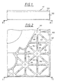
- the positioning table (101) shown in FIGS. 1 and 2 consists essentially of a support body (102) with a on it attached cover plate (3). Both bodies (101, 102) are made of the same material and consist of the same material Material (in particular silicates, Ceramics (e.g., Zerodur) and special metals (e.g., Invar) with low coefficient of thermal expansion are suitable).
- Materials in particular silicates, Ceramics (e.g., Zerodur) and special metals (e.g., Invar) with low coefficient of thermal expansion are suitable).
- the support body (102) has a lightweight structure, so that the Table (101) has the greatest possible dynamics and especially exposed to strong positive and negative acceleration forces can be.
- nodes (105) and vertices (106) are Splices (107) to which the cover plate (103) is attached to the support body (102) by gluing.
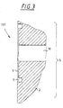
- the concrete shape of these splices (107) is in the figure 3 explained again.
- the distribution of the splices (107) between the support body (102) and the cover plate (103) can specifically the flexural rigidity of the positioning table (101) are changed so that it deforms predictably during acceleration. there but must remain as high as possible bending stiffness.
- correction values can not be stored in tables or even be calculated, you want a correction in real time to reach. They are specified by the compensation electronics and the positioning table (101) must be in its deformation or vibration behavior adapted to it.
- the splices (107) are accessible from the outside (especially on the bars (104) and at the bases (106) of the lightweight structure), the splices (107) are on the node (105) completely inside the node surfaces.
- the glue is made by circular holes (whose diameter preferably about 1 to 2 mm) in the very center of circular splices (107) supplied to this and flows in the very narrow adhesive gap (with a diameter of preferably about 6 mm) of the splice (107) by the capillary action.
- By an undercut around the adhesive gap is the Adhesive prevented from the adhesive gap of the splice (107) leave.
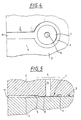
- a splice (5) consists of a flat surface (4) a counter surface (3), in which all needed for bonding Recesses are incorporated.
- These recesses are in particular a flat circular Adhesive pad (7) with a defined adhesive gap (8), which of a larger circular cutout (9) for limiting surrounded by the adhesive gap (8).
- a free cut (9) For example, the adhesive which penetrates the adhesive gap (8) can pass through Capillary forces spreads to the area of this adhesive gap (8) be limited.
- the adhesive pad (7) preferably in her Center, ends a circular cylindrical channel (10) for Incorporation of the adhesive under overpressure (preferably in Range between 1 and 5 bar, especially in the range between 3 and 4 bar).
- the free cut (9) is followed rectangular channel (11) for degassing at the Curing of the adhesive resulting gases.
- This glue insertion channel (10) should be as short as possible be so that the required pressure in the introduction of the Glue must not be too high.
- the free cut (9) should be a 2 mm larger Have diameter and be as thick as 0.5 mm.
- the Volume ratio of splice (5) to free cut (9) is then around 1: 4, with a value of 1: 3 not below should be.
- the free cut (9) in this example is about 69% of the connecting surface (3, 4) enclosed because of the degassing (11) ends in the cutout (9).
- the degassing channel (11) himself is up to his exit from the two Bodies (1, 2) on both sides of the connecting surface (3, 4) enclosed.
- the rectangular channel (11) for degassing during curing of the adhesive gas should double Width of the free cut (9) and have the same height. at but its dimensions must also take into account its length to ensure good degassing. He can be smaller be selected when the splice (5) near the edge of the two bodies to be connected (1, 2) is arranged and must be selected larger, if the splice (5) continues in the Inside the two bodies (1, 2) is located.
- the circular cylindrical channel (10) for introducing the Klebers has in the example shown here a radius of a quarter of the radius of the adhesive pad (7) (wherein its Dimensioning also depending on the viscosity of the used adhesive) and should be as short as possible be.
- a dividing wall (13) By placing in the middle of the channel (11 ') a dividing wall (13) Insert creates two channels (12a, 12b), which in the Free cut (9) ends. In the one channel (12a) you can then inject a gas (e.g., air) through the other channel (12b) can escape. Thus one generates a directed gas flow around the adhesive pad (7) in the free cut (9), whereby the Size of the degassing channel (11 ') even with very long length in acceptable limits.
- a gas e.g., air
- one or both may be themselves slightly roughened opposite surfaces of the adhesive pad (7) be. Whether this makes sense depends on the viscosity of the product used adhesive and the adhesive gap thickness or width, since the glue yes the whole adhesive pad (7) to the free cut (9) to fill out.
- UV-curing adhesive it may make sense be, the walls of the degassing (11, 11 ') and the free cutting (9) at least partially to be mirrored by the Degassing channel (11, 11 ') in addition UV light to the adhesive pad (7) to bring.
- the channel (10) for insertion to dispense with the adhesive when taking a glue, which after introduction, only by external action (e.g. Heating, irradiation of UV light, etc.) a curing, optionally with an increase in volume of the adhesive experiences.
- the correct bonding process is then triggered with a time delay.
- the quantity dosage of the adhesive is very critical.
- connection surface (3, 4) For the strength of the connection between the two bodies (1, 2) is in particular the placement of the adhesive pad (7) within the connection surface (3, 4) important. Especially advantageous is also the flat degassing duct (11, 11 ') (which ensures good degassing) and the round channel (10) for introducing the adhesive (which is the introduction of the adhesive has the least possible resistance).
- the round adhesive pad (7) with a channel opening in its center ensures a clean flow of glue as well as for a Low-tension splice.
- the splices are preferably in To place the height of the shear center.
- the recesses for carrying out the bonding are in the above example only incorporated on one of the contact surfaces, because this is easier to manufacture. Of course One part of the recesses could also be on the opposite Be incorporated contact surface, which, however Adjustment problems would result.
- the transition between the second body (2) and the first Body (1) i.e., the inner edge
- the transition between the second body (2) and the first Body (1) i.e., the inner edge
- the transition between the second body (2) and the first Body (1) i.e., the inner edge
- the first vertical freestanding wall of the second body (2) is mirrored and for position measurement of the assembled Body 81, 2) is used.
- the body to be made consists of two separate ones Bodies (1, 2), which joined together into a single part become.
- the so resulting body (1, 2) is characterized by a very high Form accuracy with high load capacity compared to Spurts off.
- the previously described body (1,2) is the Platen (1) for an X-Y-Z positioning table, which in Microscopes is used, which radiations in the UV range to check the parts to be inspected.
- Positioning tables with their support plates (1) must be in highest dimensionally stable and at the same time a high Possess strength, which rapid movements of the table in particular with an automation of the control tasks allowed.
- the adhesive with a possible low shrinkage (less than 10%, better less than 3% and still better less than 1% or less than 0.6%) can be the desired Assist in reducing the amount of herbs.
- Adhesives which have the lowest possible shrinkage and which a secure bond with the material to be joined Body allow.
- Silicate and ceramic these are especially epoxy with a shrinkage of less than 3% or less than 0.6%.
- the splices in the interface between the two To connect bodies does not just provide a safe Connection of the two bodies to be joined together, especially with strong accelerations or their change, but also allows adjustment of the vibration behavior of the connected body. Your holding power must therefore In particular, they only become fully effective when they become effective connecting bodies at their joining surfaces from each other want to solve. This may depend on the geometry of the connected Body and the location of the interfaces relative to the or the acceleration directions take place at different speeds.
- the adhesive feed channel could also by the other of the bodies to be connected introduce the adhesive gap and the venting channel inside the body, far be arranged away from the connecting surfaces.
- connection between two bodies described below (30, 31) uses a stress-reducing element (37) (which can also be called compensation body), which is inserted between two bonds and which by the shrinkage of the adhesive caused forces in the form of Tensions in itself absorbs.
- the adhesive bond thus obtained causes much less deformation of the finer ones Bodies (30, 31) than in the prior art known joining techniques.
- the physical background for the deformation caused by adhesion in the joined bodies (30, 31) is essentially due to the shrinkage of the adhesive.
- F / A E * ⁇ with the force F, the adhesive surface A and the modulus of elasticity E. This results
- F / A E * ⁇ l / l 0 ⁇
- F and thus the force on the splice (43), should be as small as possible, then A or E must be reduced because ⁇ l given by the shrinkage of the adhesive and l 0 by the or the two adhesive gaps (41, 42 ) (whose thickness can not be arbitrarily reduced, for example, by the necessity of the introduction of the adhesive) is given.
- the area A can not be reduced arbitrarily and is essentially determined by the required holding forces.
- the modulus of elasticity is determined by the adherends (30, 31).
- this body (37) which between two splices in a cavity (34) between the to be bonded body (30, 31) is introduced, can be Select cross-sectional area and / or the modulus of elasticity.
- the bodies to be connected (30, 31) are preferably made the same material (because of the thermal expansion coefficient e.g. Silicate, ceramic or invar) and possess each a connecting surface (32, 33), to which they glued together. Before the gluing is done in one Body (31) to the connection surface (33) open towards cavity (34) (in the desired shape, for example rectangular or round cylinders) in which two channels (35, 36) terminate.
- the thermal expansion coefficient e.g. Silicate, ceramic or invar
- this cavity (34) At the bottom of this cavity (34) is a compensation element (37) with a first adhesive gap (44) glued so that between the compensating element (37) and the side walls (39a, 39b) of the cavity (34) circumferentially an air gap (40, 41) remains.
- a first channel (35) drilled, which later in the middle of the second adhesive gap (42) ends and through which the adhesive supply for the second splice on Compensation element (37) to take place.
- Side of the air gap (40) a further recess is mounted, which in assembled state of the two bodies (30, 31) one second channel (36) forms.
- the adhesive feed channel (35) could also through the second (30) of the bodies (30, 31) to be joined bring the second adhesive gap (42) and the venting channel (36) inside the body (31), far away from the connecting surfaces (32, 33) may be arranged.
- FIG. 9 shows a modification of FIG. 8 shown splice (43 in Figure 8).
- the modification relates only to the shape of the Compensating elements (37 in Figure 9) and the position of the adhesive supply channel (35 in Figure 9).
- the one of the FIGS connecting body (46) has a cavity (47) and a recess generated for an air outlet channel (48), wherein the Dimensioning of the cavity (47) has a circumferential air gap (49) around the compensating element (50) to be glued in between this and the lateral wall of the cavity (47) ensures.
- the compensating element (50) is made by means of an adhesive mounted in the cavity (47), wherein the adhesive the whole first adhesive gap (51) fills.
- the two Body (45, 46) on the two opposite Connecting surfaces (53, 54) placed together so that in the second body (45) attached adhesive feed channel (55) as exactly as possible in the middle of the adhesive surface above the Compensation element (50) ends.
- the glue supply then takes place again as already described for Figure 8, wherein the adhesive Here too fill the adhesive gap (52) as completely as possible should.
- the compensation element (50) which is for Recording of tensile forces and bending forces serves a circumferential Cross-section reduction below that used for bonding Adhesive plates (50a, 50b) at the ends of the elongated body (50c).
- This cross-sectional reduction produces the in FIG. 8 described effect even if the modulus of elasticity of the Material of the compensation element (50) the same or even more is greater than the modulus of elasticity of the body to be joined (45, 46).
- connection surface (62) of the first to be connected Body (60) is an upwardly open cavity (64) with the desired (preferably circular) cross-section, in the bottom of a degassing duct (66) ends.
- this cavity (64) is before the joining of the two to be connected body (60, 61) a longitudinally slotted, inside hollow connecting tube (68) laterally on an at least almost completely circumferential adhesive gap (72) glued so that Bottom of the cavity (64) still an air gap (69) in particular remains adhesive and the compensation element (68) above the Bottom of the cavity (64) ends.
- connection surface (63) of the second to be connected Body (61) is also an open at the top Cavity (65) with the desired (preferably circular) Cross-section, in which laterally, about in the middle of the later to be produced adhesion, an adhesive feed channel (67) ends.
- This cavity (65) has at its the connection surface (63) proximate end a circumferential groove (70) with a larger one Diameter than the rest of the cavity (65).
- This groove (70) is needed to control the adhesive flow caused by capillary forces between the connecting tube (68) and the second body (61) to stop.
- This cavity (65) is slightly larger as the cavity (64) in the other body to be joined (60), to make a subsequent adjustment of the two to allow connecting body (60, 61) to each other.
- the adhesive feed channel should after performing the Bonding should preferably be as free of glue as possible.
- the splices in the Anspreng vom between the two too connecting bodies serve to connect the two connecting body with each other, especially in strong Accelerations or their change safely. Your holding power In particular, it must become fully effective only when the bodies to be joined at their joining surfaces want to solve each other. This can vary depending on the geometry of the connected body and the location of the connecting surfaces relative different from the acceleration direction (s) done quickly.
- the connection surfaces can additionally be joined together by a Ansprengung.
- the cavity for receiving the compensating element must in the Figures 8 and 9 not in just one of the two bodies be educated. Just as well can be split and off two as closely as possible opposite cavities be formed. However, this modification has the disadvantage that a more precise adjustment of the two bodies to be joined must be made to each other in the bonding. In special cases but this solution could also be advantageous.
- the support body and the cover plate are preferably (off Thermal stability reasons) of the same material, each of the two bodies having at least one interface has, which are opposite.
- At least One of the two connection surfaces is one or more Recesses for a splice or adhesive gap attached, being an adhesive for an adhesive bond of the two Connecting surfaces at the or the splices between the ensures both bodies.
- both bodies can be spread apart be.
- the splices do not have to be complete lie in the Anspreng composition.
- At a Ansprengung of the two Body to each other can be a flaking surface of one be completed on the additional adhesive channel two bodies preferably around the edge of the Anspreng lake or in a groove between the two bodies at the Anspreng lake is arranged.
- the Anspreng lake enclose the splice as completely as possible, at least however, more than 50%, preferably more than 60% and still preferably more than 65%.
- a first channel can be used to introduce the adhesive in the splice is provided and should preferably be circular be.
- a second channel can be used for an air connection to be attached Bonding and thus to bleed the splice serve and is preferably rectangular.
- the second Channel is useful until the free cut to the gluing area led, whereby the second channel and the free cut preferably at least three times, preferably five times Thickness of the inner adhesive area has and the second channel and the cutout have the same thickness.
- splice should equal height of Shear center of the two bodies are placed and they preferably have an inner flat circular cylindrical Adhesive area on and around this inner gluing area should be one they enclosing outer circular cylindrical free punch be arranged to prevent the escape of the glue from the To prevent splice.
- the positioning table according to the invention consists essentially from a carrying body and a cover plate. It can the Carrying body composed of different wear bodies or be worked out of one part (homogeneous body).
- the support body can be the most diverse, according to the application have optimized design (for example, from closed or open polygonal bodies (with triangular, quadrilateral, Pentagonal, hexagonal, etc. n-ecks surfaces), an embodiment like the "Atomium” (nodes (e.g., spheres, cubes, etc.) with connecting bars (round or polygonal), etc.).
- optimized design for example, from closed or open polygonal bodies (with triangular, quadrilateral, Pentagonal, hexagonal, etc. n-ecks surfaces), an embodiment like the "Atomium” (nodes (e.g., spheres, cubes, etc.) with connecting bars (round or polygonal), etc.).
- the positioning table can be side and bottom open or be closed and the cover plate can be on any side be attached to the support body (not necessarily above).
- the material of the support body can be made of a single material There may or may be different materials to build be used of the support body. To make the carrying body lighter To make, this has a variety of recesses (Lightweight structure).
- cover plate On the support body of the positioning table is a separate mounted cover plate attached, which consists of either several Parts are composed or made of a homogeneous part consists.
- the material of the cover plate can from a single material or it can be different Materials used for the production.
- the thermal expansion coefficient of the materials of the support body and the cover plate should be as small as possible and differ by a maximum of 2 * 10 -6 mm / K. This difference in the coefficient of thermal expansion of the materials of the support body and cover plate tends to zero, if both are made of the same material.
- materials for the support body and the cover plate in particular invar, glass or ceramic, in particular glass ceramic are suitable.
- Attachment points may be arranged, which spatially are separated from each other.
- Adjustment of the vibration behavior of the positioning table whereby these are used for a wide variety of devices can.
- electronics engineer to develop the positioning electronics independent of the positioning table or allows him to avoid critical resonance points.
- the maximum extent of at least 50% of the attachment points should be less than 12mm, at least approximately a punctiform attachment of the cover plate on the To get support body.
- this punctiform But fixing allows an optimal adaptation of the Vibration behavior of the positioning table to the application spectrum and allows manufacturing variations in the item production by clever positioning of the attachment points to catch each other.
- the attachment of the cover plate to the support body can by blowing in combination with one of the fastening techniques Bonding, soldering or welding, done, depending on the used Materials and the required job profile.
- Bonding fastening
- soldering soldering
- welding done, depending on the used Materials and the required job profile.
- the bonding technique in combination with Ansprengung in question.
- Invar as material of the Positioning table offers in particular a gluing, soldering, Welding or a combination of these fastening techniques at.
- the thickness of the cover plate should be sized so that they Can absorb stresses of the support body. Your thickness should be but be as small as possible, around the positioning table as easy as possible (and thus the Verstelldynamik as big as possible). This is especially true for larger ones Positioning tables then reached when the thickness of the cover plate smaller than 2 mm and larger than 0.5 mm.
- the support body should recesses below the cover plate for receiving adjusting elements, so that the overall dimensions of the table can be kept small.
- the positioning table can be used in particular in optical devices be installed, which at a wavelength less than 400 nm work. Since the dimensional stability of the positioning table at professional execution in the nanometer range (i.e. 100 nm up to 10nm) can, in particular with him Components with very small structures in an optical device be stored very accurately.
- Such optical instrument are one or more Lenses and / or one or more reflective elements arranged.
- a microscope which preferably with electromagnetic Waves from the UV range works.
Landscapes
- Physics & Mathematics (AREA)
- General Physics & Mathematics (AREA)
- Optics & Photonics (AREA)
- Mechanical Engineering (AREA)
- Analytical Chemistry (AREA)
- Engineering & Computer Science (AREA)
- Chemical & Material Sciences (AREA)
- Mounting And Adjusting Of Optical Elements (AREA)
- Standing Axle, Rod, Or Tube Structures Coupled By Welding, Adhesion, Or Deposition (AREA)
- Exposure And Positioning Against Photoresist Photosensitive Materials (AREA)
- Adhesives Or Adhesive Processes (AREA)
- Workshop Equipment, Work Benches, Supports, Or Storage Means (AREA)
- Details Of Measuring And Other Instruments (AREA)
Claims (14)
- Table de positionnement avec au moins un support possédant une multiplicité d'évidements et avec au moins une plaque de recouvrement, caractérisée en ce que le matériau du support et de la plaque de recouvrement est du verre ou de la céramique, en particulier de la céramique de verre et que la plaque de recouvrement est fixée sur le support par plaquage en combinaison avec une des techniques de fixation par collage, par brasure ou par soudure.
- Table de positionnement selon la revendication 1, caractérisée en ce que les coefficients de dilatation thermique des matériaux du support et de la plaque de recouvrement sont différents au maximum de 2*10-6 mm/K.
- Table de positionnement selon la revendication 1 ou 2, caractérisée en ce que plusieurs points de fixation séparés dans l'espace sont disposés entre le support et la plaque de recouvrement.
- Table de positionnement selon la revendication 3, caractérisée en ce que la dilation maximale est inférieure à 12 mm à au moins 50% des points de fixation.
- Table de positionnement selon une des revendications 1 à 4, caractérisée en ce que la plaque de recouvrement a une épaisseur maximum de 2 mm.
- Table de positionnement selon une des revendications 1 à 5, caractérisée en ce que le support est constitué de noeuds et de branches disposés en deux ou trois dimensions, la section transversale des branches étant plus petite que la section transversale des noeuds.
- Table de positionnement selon une des revendications 1 à 6, caractérisée en ce qu'au-dessous de la plaque de recouvrement, le support présente des évidements pour recevoir des éléments de réglage.
- Table de positionnement selon une des revendications 1 à 7, caractérisée en ce qu'une ouverture est disposée au centre du support.
- Table de positionnement selon une des revendications 1 à 8, caractérisée en ce que des points de collage sont disposés entre le support et la plaque de recouvrement et que ces points de collage sont ronds.
- Table de positionnement selon une des revendications 1 à 9, caractérisée en ce que le support et la plaque de recouvrement sont du même matériau.
- Appareil optique avec une table de positionnement selon une des revendications 1 à 10, caractérisé en ce que l'appareil optique fonctionne à une longueur d'onde inférieure à 400 nm.
- Appareil optique selon la revendication 11, caractérisé en ce qu'au moins une lentille est disposée dans l'appareil optique.
- Appareil optique selon la revendication 11, caractérisé en ce qu'au moins un élément réfléchissant est disposé dans l'appareil optique.
- Appareil optique selon une des revendications 11, 12 ou 13, caractérisé en ce que l'appareil optique est un microscope.
Applications Claiming Priority (2)
| Application Number | Priority Date | Filing Date | Title |
|---|---|---|---|
| DE19757529A DE19757529A1 (de) | 1997-12-23 | 1997-12-23 | Positioniertisch |
| DE19757529 | 1997-12-23 |
Publications (3)
| Publication Number | Publication Date |
|---|---|
| EP0926525A2 EP0926525A2 (fr) | 1999-06-30 |
| EP0926525A3 EP0926525A3 (fr) | 2000-01-12 |
| EP0926525B1 true EP0926525B1 (fr) | 2005-01-05 |
Family
ID=7853180
Family Applications (1)
| Application Number | Title | Priority Date | Filing Date |
|---|---|---|---|
| EP98121625A Expired - Lifetime EP0926525B1 (fr) | 1997-12-23 | 1998-11-12 | Table de positionnement |
Country Status (6)
| Country | Link |
|---|---|
| US (1) | US6111691A (fr) |
| EP (1) | EP0926525B1 (fr) |
| JP (1) | JPH11248871A (fr) |
| KR (1) | KR100566907B1 (fr) |
| DE (2) | DE19757529A1 (fr) |
| TW (1) | TW403914B (fr) |
Families Citing this family (7)
| Publication number | Priority date | Publication date | Assignee | Title |
|---|---|---|---|---|
| DE10259186A1 (de) * | 2002-12-18 | 2004-07-08 | Carl Zeiss Smt Ag | Vorrichtung zur Aufnahme von Messinstrumenten |
| WO2005103788A1 (fr) * | 2004-04-26 | 2005-11-03 | Carl Zeiss Smt Ag | Procede pour fixer un element optique a une structure de maintien |
| EP1756641A1 (fr) | 2004-05-03 | 2007-02-28 | Carl Zeiss SMT AG | Structure d'assemblage optique comprenant un corps de liaison prevu avec un moyen de compensation de la dilatation thermique |
| EP1593951B1 (fr) * | 2004-05-04 | 2014-10-29 | Oerlikon Space AG | Banc optique très stable et très léger et son utilisation dans l'espace |
| JP2008514971A (ja) * | 2004-09-27 | 2008-05-08 | ショット アクチエンゲゼルシャフト | ゼロ膨張材料で作製された複合構造物およびその製造方法 |
| GB2513320B (en) * | 2013-04-22 | 2020-07-29 | Asm Assembly Systems Singapore Pte Ltd | Table support system and table platen therefor |
| CN105499982B (zh) * | 2015-12-16 | 2018-05-22 | 韩燕� | 一种轻型刮土板成型组装机的组装辅助机构 |
Citations (3)
| Publication number | Priority date | Publication date | Assignee | Title |
|---|---|---|---|---|
| US5021282A (en) * | 1984-10-22 | 1991-06-04 | Newport Corporation | Honeycomb table manufacture and clean-room compatible honeycomb tables |
| US5061541A (en) * | 1989-12-27 | 1991-10-29 | Kinetic Systems, Inc. | Honeycomb tables |
| US5626157A (en) * | 1992-12-11 | 1997-05-06 | Melles Griot, Inc. | Optical table |
Family Cites Families (9)
| Publication number | Priority date | Publication date | Assignee | Title |
|---|---|---|---|---|
| DE2741638C3 (de) * | 1977-09-15 | 1980-03-27 | Ernst Dipl.-Phys. Dr. 8000 Muenchen Remy | Präparattrager mit Elektrodenanordnung fur die Zelluntersuchung, sowie seine Herstellung |
| US4441793A (en) * | 1983-01-10 | 1984-04-10 | Elkins Carlos D | Microscopic evaluation slide |
| US4526445A (en) * | 1983-05-05 | 1985-07-02 | Miles Laboratories, Inc. | Optical window with vacuum film holder |
| US4722598A (en) * | 1986-12-04 | 1988-02-02 | Max M. Ford | Diagnostic microscope slide having multiple sample wells and cover |
| DE3711466A1 (de) * | 1987-04-04 | 1988-10-27 | Zeiss Carl Fa | Vorrichtung zur verbindung von koerpern |
| DE3934546A1 (de) * | 1989-10-17 | 1991-04-18 | Zeiss Carl Fa | Verfahren zum verbinden von segmenten eines koerpers, vorrichtungen zur durchfuehrung des verfahrens sowie ein mittels des verfahrens hergestellter spiegel |
| US5262220A (en) * | 1991-06-18 | 1993-11-16 | Chem-Tronics, Inc. | High strength structure assembly and method of making the same |
| DE19601018A1 (de) * | 1995-01-27 | 1996-08-01 | Zeiss Carl Fa | Linear verstellbarer Präzisionstisch |
| DE19650392C2 (de) * | 1996-08-23 | 1999-07-15 | Leica Microsystems | Feinfokussiertisch |
-
1997
- 1997-12-23 DE DE19757529A patent/DE19757529A1/de not_active Withdrawn
-
1998
- 1998-11-12 EP EP98121625A patent/EP0926525B1/fr not_active Expired - Lifetime
- 1998-11-12 DE DE59812470T patent/DE59812470D1/de not_active Expired - Fee Related
- 1998-11-26 TW TW087119615A patent/TW403914B/zh not_active IP Right Cessation
- 1998-11-30 KR KR1019980051891A patent/KR100566907B1/ko not_active Expired - Fee Related
- 1998-12-18 US US09/215,318 patent/US6111691A/en not_active Expired - Fee Related
- 1998-12-22 JP JP10364435A patent/JPH11248871A/ja active Pending
Patent Citations (3)
| Publication number | Priority date | Publication date | Assignee | Title |
|---|---|---|---|---|
| US5021282A (en) * | 1984-10-22 | 1991-06-04 | Newport Corporation | Honeycomb table manufacture and clean-room compatible honeycomb tables |
| US5061541A (en) * | 1989-12-27 | 1991-10-29 | Kinetic Systems, Inc. | Honeycomb tables |
| US5626157A (en) * | 1992-12-11 | 1997-05-06 | Melles Griot, Inc. | Optical table |
Also Published As
| Publication number | Publication date |
|---|---|
| EP0926525A2 (fr) | 1999-06-30 |
| US6111691A (en) | 2000-08-29 |
| JPH11248871A (ja) | 1999-09-17 |
| TW403914B (en) | 2000-09-01 |
| KR100566907B1 (ko) | 2006-07-14 |
| KR19990062645A (ko) | 1999-07-26 |
| EP0926525A3 (fr) | 2000-01-12 |
| DE59812470D1 (de) | 2005-02-10 |
| DE19757529A1 (de) | 1999-06-24 |
Similar Documents
| Publication | Publication Date | Title |
|---|---|---|
| EP1113191B1 (fr) | Dispositif pour la transmission d'un mouvement | |
| DE102013109185B3 (de) | Optische Baugruppe mit einer Fassung mit Verbindungseinheiten gerichteter Nachgiebigkeit | |
| DE19603111A1 (de) | Lasersystem | |
| DE3502025A1 (de) | Verformbarer spiegel | |
| DE19613158A1 (de) | Hochdynamischer piezoelektrischer Antrieb | |
| DE69408752T2 (de) | Justiervorrichtung zur Ausrichtung optischer Fasern | |
| EP0922981A2 (fr) | Corps joints | |
| EP2599171B1 (fr) | Fixation d'un support d'optique ajustable dans deux directions spatiales à l'aide d'un adhésif rétractable | |
| DE10037975C1 (de) | Verstellvorrichtung und Verfahren zu ihrer Justierung | |
| DE19757529A1 (de) | Positioniertisch | |
| DE102010026252B4 (de) | Lichtintegrator für rechteckige Strahlquerschnitte unterschiedlicher Abmessungen | |
| DE102012213671A1 (de) | Spiegelanordnung für eine EUV-Lithographieanlage und Verfahren zur Herstellung derselben | |
| EP3252443B1 (fr) | Articulation de minces | |
| DE102016102469B3 (de) | Optische Fassung mit wenigstens einer Klemmeinheit mit Klebespalt | |
| EP0922982A2 (fr) | Corps joints | |
| EP3798588A1 (fr) | Bloc de pesage monolithique | |
| DE10358200B4 (de) | Stabförmiges, hochbelastbares, aktives Verbindungselement sowie Drehflügelflugzeug mit einem solchen Verbindungselement | |
| EP1053576B1 (fr) | Procede pour constituer et assembler des composants optiques, notamment les composants optiques d'un resonateur laser et resonateur laser correspondant | |
| WO1992012358A1 (fr) | Ressort a boudin | |
| EP4402092B1 (fr) | Membrane de verre monolithique, agencement de membrane verticale double, structure de ressort micromécanique et procédé de production associé | |
| DE102016110151A1 (de) | Dünnstellengelenk | |
| DE102015101384B3 (de) | Optische Fassung mit wenigstens einer Klemmeinheit mit einer Druckschraube | |
| EP1593951A2 (fr) | Banc optique très stable et très léger et son utilisation dans l'espace | |
| DE102005049731A1 (de) | Optischer Aufbau mit elastischer Aufhängung und Verfahren zur Herstellung eines solchen | |
| DE102018101960B3 (de) | Spiegelbaugruppe mit einem Planspiegel und einer Stützstruktur |
Legal Events
| Date | Code | Title | Description |
|---|---|---|---|
| PUAI | Public reference made under article 153(3) epc to a published international application that has entered the european phase |
Free format text: ORIGINAL CODE: 0009012 |
|
| AK | Designated contracting states |
Kind code of ref document: A2 Designated state(s): DE FR GB IE IT NL |
|
| AX | Request for extension of the european patent |
Free format text: AL;LT;LV;MK;RO;SI |
|
| PUAL | Search report despatched |
Free format text: ORIGINAL CODE: 0009013 |
|
| AK | Designated contracting states |
Kind code of ref document: A3 Designated state(s): AT BE CH CY DE DK ES FI FR GB GR IE IT LI LU MC NL PT SE |
|
| AX | Request for extension of the european patent |
Free format text: AL;LT;LV;MK;RO;SI |
|
| RIC1 | Information provided on ipc code assigned before grant |
Free format text: 7G 02B 21/26 A |
|
| 17P | Request for examination filed |
Effective date: 20000520 |
|
| AKX | Designation fees paid |
Free format text: DE FR GB IE IT NL |
|
| 17Q | First examination report despatched |
Effective date: 20031110 |
|
| GRAP | Despatch of communication of intention to grant a patent |
Free format text: ORIGINAL CODE: EPIDOSNIGR1 |
|
| RAP1 | Party data changed (applicant data changed or rights of an application transferred) |
Owner name: CARL-ZEISS-STIFTUNG TRADING AS CARL ZEISS Owner name: CARL ZEISS |
|
| RAP1 | Party data changed (applicant data changed or rights of an application transferred) |
Owner name: CARL ZEISS SMT AG |
|
| RAP1 | Party data changed (applicant data changed or rights of an application transferred) |
Owner name: CARL ZEISS SMT AG |
|
| GRAS | Grant fee paid |
Free format text: ORIGINAL CODE: EPIDOSNIGR3 |
|
| GRAA | (expected) grant |
Free format text: ORIGINAL CODE: 0009210 |
|
| AK | Designated contracting states |
Kind code of ref document: B1 Designated state(s): DE FR GB IE IT NL |
|
| PG25 | Lapsed in a contracting state [announced via postgrant information from national office to epo] |
Ref country code: IT Free format text: LAPSE BECAUSE OF FAILURE TO SUBMIT A TRANSLATION OF THE DESCRIPTION OR TO PAY THE FEE WITHIN THE PRESCRIBED TIME-LIMIT;WARNING: LAPSES OF ITALIAN PATENTS WITH EFFECTIVE DATE BEFORE 2007 MAY HAVE OCCURRED AT ANY TIME BEFORE 2007. THE CORRECT EFFECTIVE DATE MAY BE DIFFERENT FROM THE ONE RECORDED. Effective date: 20050105 Ref country code: IE Free format text: LAPSE BECAUSE OF FAILURE TO SUBMIT A TRANSLATION OF THE DESCRIPTION OR TO PAY THE FEE WITHIN THE PRESCRIBED TIME-LIMIT Effective date: 20050105 Ref country code: GB Free format text: LAPSE BECAUSE OF FAILURE TO SUBMIT A TRANSLATION OF THE DESCRIPTION OR TO PAY THE FEE WITHIN THE PRESCRIBED TIME-LIMIT Effective date: 20050105 |
|
| REG | Reference to a national code |
Ref country code: GB Ref legal event code: FG4D Free format text: NOT ENGLISH |
|
| REG | Reference to a national code |
Ref country code: IE Ref legal event code: FG4D Free format text: GERMAN |
|
| REF | Corresponds to: |
Ref document number: 59812470 Country of ref document: DE Date of ref document: 20050210 Kind code of ref document: P |
|
| GBV | Gb: ep patent (uk) treated as always having been void in accordance with gb section 77(7)/1977 [no translation filed] |
Effective date: 20050105 |
|
| REG | Reference to a national code |
Ref country code: IE Ref legal event code: FD4D |
|
| PLBE | No opposition filed within time limit |
Free format text: ORIGINAL CODE: 0009261 |
|
| STAA | Information on the status of an ep patent application or granted ep patent |
Free format text: STATUS: NO OPPOSITION FILED WITHIN TIME LIMIT |
|
| 26N | No opposition filed |
Effective date: 20051006 |
|
| ET | Fr: translation filed | ||
| REG | Reference to a national code |
Ref country code: GB Ref legal event code: FG4D Free format text: NOT ENGLISH |
|
| PGFP | Annual fee paid to national office [announced via postgrant information from national office to epo] |
Ref country code: NL Payment date: 20071119 Year of fee payment: 10 Ref country code: DE Payment date: 20071123 Year of fee payment: 10 |
|
| PGFP | Annual fee paid to national office [announced via postgrant information from national office to epo] |
Ref country code: FR Payment date: 20071122 Year of fee payment: 10 |
|
| PG25 | Lapsed in a contracting state [announced via postgrant information from national office to epo] |
Ref country code: NL Free format text: LAPSE BECAUSE OF NON-PAYMENT OF DUE FEES Effective date: 20090601 |
|
| NLV4 | Nl: lapsed or anulled due to non-payment of the annual fee |
Effective date: 20090601 |
|
| REG | Reference to a national code |
Ref country code: FR Ref legal event code: ST Effective date: 20090731 |
|
| PG25 | Lapsed in a contracting state [announced via postgrant information from national office to epo] |
Ref country code: DE Free format text: LAPSE BECAUSE OF NON-PAYMENT OF DUE FEES Effective date: 20090603 |
|
| PG25 | Lapsed in a contracting state [announced via postgrant information from national office to epo] |
Ref country code: FR Free format text: LAPSE BECAUSE OF NON-PAYMENT OF DUE FEES Effective date: 20081130 |