EP0926657B1 - Verfahren und Vorrichtung zum akustischem Nachweiss eines Signals mit niedrigem Signal-Rauschabstand bei zusätzlicher Anwesenheit einer Rauschquelle - Google Patents
Verfahren und Vorrichtung zum akustischem Nachweiss eines Signals mit niedrigem Signal-Rauschabstand bei zusätzlicher Anwesenheit einer Rauschquelle Download PDFInfo
- Publication number
- EP0926657B1 EP0926657B1 EP98403156A EP98403156A EP0926657B1 EP 0926657 B1 EP0926657 B1 EP 0926657B1 EP 98403156 A EP98403156 A EP 98403156A EP 98403156 A EP98403156 A EP 98403156A EP 0926657 B1 EP0926657 B1 EP 0926657B1
- Authority
- EP
- European Patent Office
- Prior art keywords
- antenna
- signal
- acoustic
- support
- noise
- Prior art date
- Legal status (The legal status is an assumption and is not a legal conclusion. Google has not performed a legal analysis and makes no representation as to the accuracy of the status listed.)
- Expired - Lifetime
Links
Images


Classifications
-
- G—PHYSICS
- G01—MEASURING; TESTING
- G01V—GEOPHYSICS; GRAVITATIONAL MEASUREMENTS; DETECTING MASSES OR OBJECTS; TAGS
- G01V1/00—Seismology; Seismic or acoustic prospecting or detecting
- G01V1/001—Acoustic presence detection
-
- G—PHYSICS
- G01—MEASURING; TESTING
- G01H—MEASUREMENT OF MECHANICAL VIBRATIONS OR ULTRASONIC, SONIC OR INFRASONIC WAVES
- G01H3/00—Measuring characteristics of vibrations by using a detector in a fluid
-
- G—PHYSICS
- G01—MEASURING; TESTING
- G01S—RADIO DIRECTION-FINDING; RADIO NAVIGATION; DETERMINING DISTANCE OR VELOCITY BY USE OF RADIO WAVES; LOCATING OR PRESENCE-DETECTING BY USE OF THE REFLECTION OR RERADIATION OF RADIO WAVES; ANALOGOUS ARRANGEMENTS USING OTHER WAVES
- G01S3/00—Direction-finders for determining the direction from which infrasonic, sonic, ultrasonic or electromagnetic waves, or particle emission, not having a directional significance, are being received
- G01S3/80—Direction-finders for determining the direction from which infrasonic, sonic, ultrasonic or electromagnetic waves, or particle emission, not having a directional significance, are being received using ultrasonic, sonic or infrasonic waves
- G01S3/86—Direction-finders for determining the direction from which infrasonic, sonic, ultrasonic or electromagnetic waves, or particle emission, not having a directional significance, are being received using ultrasonic, sonic or infrasonic waves with means for eliminating undesired waves, e.g. disturbing noises
-
- G—PHYSICS
- G10—MUSICAL INSTRUMENTS; ACOUSTICS
- G10K—SOUND-PRODUCING DEVICES; METHODS OR DEVICES FOR PROTECTING AGAINST, OR FOR DAMPING, NOISE OR OTHER ACOUSTIC WAVES IN GENERAL; ACOUSTICS NOT OTHERWISE PROVIDED FOR
- G10K11/00—Methods or devices for transmitting, conducting or directing sound in general; Methods or devices for protecting against, or for damping, noise or other acoustic waves in general
- G10K11/16—Methods or devices for protecting against, or for damping, noise or other acoustic waves in general
- G10K11/175—Methods or devices for protecting against, or for damping, noise or other acoustic waves in general using interference effects; Masking sound
- G10K11/178—Methods or devices for protecting against, or for damping, noise or other acoustic waves in general using interference effects; Masking sound by electro-acoustically regenerating the original acoustic waves in anti-phase
- G10K11/1785—Methods, e.g. algorithms; Devices
- G10K11/17857—Geometric disposition, e.g. placement of microphones
-
- G—PHYSICS
- G10—MUSICAL INSTRUMENTS; ACOUSTICS
- G10K—SOUND-PRODUCING DEVICES; METHODS OR DEVICES FOR PROTECTING AGAINST, OR FOR DAMPING, NOISE OR OTHER ACOUSTIC WAVES IN GENERAL; ACOUSTICS NOT OTHERWISE PROVIDED FOR
- G10K11/00—Methods or devices for transmitting, conducting or directing sound in general; Methods or devices for protecting against, or for damping, noise or other acoustic waves in general
- G10K11/16—Methods or devices for protecting against, or for damping, noise or other acoustic waves in general
- G10K11/175—Methods or devices for protecting against, or for damping, noise or other acoustic waves in general using interference effects; Masking sound
- G10K11/178—Methods or devices for protecting against, or for damping, noise or other acoustic waves in general using interference effects; Masking sound by electro-acoustically regenerating the original acoustic waves in anti-phase
- G10K11/1787—General system configurations
- G10K11/17879—General system configurations using both a reference signal and an error signal
- G10K11/17881—General system configurations using both a reference signal and an error signal the reference signal being an acoustic signal, e.g. recorded with a microphone
-
- G—PHYSICS
- G10—MUSICAL INSTRUMENTS; ACOUSTICS
- G10K—SOUND-PRODUCING DEVICES; METHODS OR DEVICES FOR PROTECTING AGAINST, OR FOR DAMPING, NOISE OR OTHER ACOUSTIC WAVES IN GENERAL; ACOUSTICS NOT OTHERWISE PROVIDED FOR
- G10K2210/00—Details of active noise control [ANC] covered by G10K11/178 but not provided for in any of its subgroups
- G10K2210/10—Applications
- G10K2210/122—Seismics
Definitions
- the present invention relates to methods and devices for acoustic detection in the presence of sources of parasitic noise.
- the technical sector of the invention is that of protection against noise and other acoustic waves.
- the main application of the invention is to allow a better identification and localization of acoustic sources unknown, mainly in the field of underwater acoustics.
- the antennas currently used are formed by a network of sensors (hydrophones) sensitive to pressure variations acoustic and which are installed on carrier ships, which are surface vessels or submarines.
- the operation of these the latter however induces parasitic noises which are perceived by the said antennas and whose main sources are: machines rotating which induce vibrations which propagate along the hull, the sound of water flowing along the hull and the sound of propulsion generated by the propellers and which is carried by both fluid routes in water and solid routes through the hull.
- the so-called parasitic noises can then be sufficiently important to prevent detection by said antennas of sources external acoustics that we want to be able to detect. So at this day, we try to isolate from these parasitic noises the antennas by placing essentially on the one hand anti-vibration pads between the hull and the antenna to reduce the transmission of vibrations and on the other hand an acoustic barrier between the shell and the antenna. Moreover, the elastomeric coatings and the size of the hydrophones are chosen for filter the propagation of flow noise especially for flank antennas. For the shell antennas located in the cavities of the sonar, the protective domes are studied to reduce the noises due to flow.
- Active complementary devices are also used such than that described in patent application WO901926 and teaching methods and devices for reducing emission of submarine noise submerged thanks to the controlled movement of a double shell surrounding the noise source, such as the propulsion engine, in order to impose on this double shell a movement in opposition to that created by the said noise source, which theoretically allows to cancel the effects of vibration towards the outside of the hull.
- the problem is therefore to improve the efficiency of the insulation an antenna or any acoustic measurement and measurement receiver, with respect to any noise or vibration from a known source, such as those generated by the vehicle carrying the antenna and which in the main application of the invention is a ship, and this especially in low frequencies.
- said installation is installed acoustic measurement receiving antenna on the hull of a ship which carries the said sources of parasitic noise and we place at least one reference sensor, which can then be a hydrophone, close to propulsion propellers of the ship and at least one other inside the shell on any structure that can be a source of vibration.
- Figure 1 is a schematic sectional view of a device for detection according to the invention installed on and in a ship's hull.
- Figure 2 is an installation diagram made during a experiment carried out in an air environment according to the method of the invention.
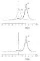
- Figures 3 to 6 are curves representative of the results of measurements taken with the device in Figure 2 and following different noise signal detection and processing configurations.
- the acoustic detection devices represented in FIGS. 1 and 2 comprise at least one receiving antenna 2, which in the example in FIG. 1 is a sonar antenna, and in the example in FIG. 2 a linear antenna composed of sensors microphones 2 1 placed on a thin plate 3, for carrying out any acoustic measurement and measurement, and associated with a unit 10 for processing the signal thus detected by the antenna 2.
- the reference sensors 7 can be accelerometers, strain gauges, or other vibration sensors placed on machines 1 2 or on the hull 3, or hydrophones 7 1 placed near or propulsion propeller 1 1 , or any other specific sensor placed in the flow responsible for the hydrodynamic noise to measure the latter, in particular sensitive to shear stress.
- the detection device can comprise at least one other vibration sensor 7 3 placed directly on at least one of said noise sources, and actuators 5 fixed to said support 20 of the antenna 2 and controlled by the so-called active control system 8.
- some of the reference vibration sensors 7 are common to both the signal processing system 9,10 and the active control system 8.
- the active pads 4 are used to control the vibration transmission from hull 3 and actuators 5 reduce the effects of acoustic radiation by near field coming from the hull on antenna 2.
- System 8 control dynamics is programmed using specific algorithms intended to calculate from the measurements taken by the error sensor 6 and of the results of the processing of the signals received by the antenna 2, the order signals to be sent to the active pads 4 and to the actuators 5 to reduce the level of vibrations of the support 20.
- Said programming of the control system can be based on different types of known algorithms such as that described in the "Journal Of Sound and Vibration” (1995) following the article by Gentlemen VIPPERMAN and FULLER entitled “Active control of broadband structural vibration using LMS adaptive algorithm ".
- the known parasitic vibrations are generated directly on the structure 3 representing the shell, by a vibrating pot 1 3 supplied by a signal generator 11 of harmonic frequency through a power amplifier : the vibration or parasitic noise reference signal which must be sent to the active control system 8 is obtained by means of a switch 21 either directly from the generator 11, or by means of an accelerometer 7 3 placed on the structure 3 representative of the hull.
- the "unknown" external acoustic source that we want to detect is a loudspeaker 13 supplied by a noise generator 14 with broadband noise placed a few meters from the antenna 2 and making an angle ⁇ with respect to the axis of it.
- the error sensors are two accelerometers 6 placed near the points of attachment of the active studs 4 on the support 3 of the antenna 2 and the assembly is placed on a fixed reference support 12. With such an installation, was thus able to take different measurements and perform different signal processing with two excitation sources of the same frequency band, around 590 Hz, one of said two sources corresponding to the natural noise created by the vibration of the structure 3 (and represented only by curve 15 in FIG. 3), and another corresponding to the source of the external noise 13 (and represented alone by curve 16 in FIG. 3).
- the said curves in all of FIGS. 3 to 6 represent the signals picked up by the antenna 2 after processing 10 and with or without conditioning 10.
Landscapes
- Physics & Mathematics (AREA)
- Acoustics & Sound (AREA)
- Engineering & Computer Science (AREA)
- Multimedia (AREA)
- General Physics & Mathematics (AREA)
- Life Sciences & Earth Sciences (AREA)
- Remote Sensing (AREA)
- Environmental & Geological Engineering (AREA)
- Geology (AREA)
- General Life Sciences & Earth Sciences (AREA)
- Geophysics (AREA)
- Radar, Positioning & Navigation (AREA)
- Measurement Of Mechanical Vibrations Or Ultrasonic Waves (AREA)
- Measurement Of Velocity Or Position Using Acoustic Or Ultrasonic Waves (AREA)
- Geophysics And Detection Of Objects (AREA)
Claims (10)
- Verfahren zur Schallerfassung, hauptsächlich im Bereich der Unterseeakustik, in Gegenwart von Störgeräuschquellen (1, 3) mit geringen Rauschabständen, und unter Verwendung von mindestens einer Antenne zum Messen von Schalldrücken, die mit einer Einheit (10) zur Verarbeitung des Signals verbunden ist, dadurch gekennzeichnet, daß:man zumindest einen Sensor für eine Schallschwingung oder zum Messen einer mechanischen Beanspruchung (71) direkt an mindestens einer der Geräuschquellen (11) anordnet, von welchen man so das Störsignal schon an seinem Ursprung feststellt und das dann als Bezugssignal genommen wird,man den Teil des von der Antenne (2) georteten Signals beseitigt (9), der mit dem Bezugsstörsignal korreliert ist,man den Träger (20) zwischen dem Rumpf eines Schiffs und der Antenne (2) mit einem dynamischen Bewegungskontrollsystem (4, 5, 8) verbindet und man die Schwingungen des Trägers der Antenne (2) durch jeden Fehlersensor (6), der mit diesem verbunden ist, mißt, wobei das System mindestens einen Schwingungssensor (72) für eine bekannte Störgeräuschquelle (12) umfaßt,man das dynamische System (4, 5) derart steuert (8), daß das vom Fehlersensor (6) festgestellte Signal minimal ist,man dann die Eigenschaften jeder anderen unbekannten, äußeren, möglicherweise akustischen Quelle bestimmt (10).
- Erfassungsverfahren nach Anspruch 1, dadurch gekennzeichnet, daß:man zumindest einen Schwingungssensor (73) direkt an mindestens einer der Geräuschquellen (3) anordnet,man an dem Träger (20) der Antenne (2) Stellantriebe (5) befestigt, die man durch das Bezugsstörsignal der Quelle (3) des gemessenen Geräuschs derart steuert (8), daß die Wirkungen der Schallstrahlung im Nahfeld von dieser auf den Träger (20) der Antenne (2) minimal sind.
- Erfassungsverfahren nach einem der Ansprüche 1 oder 2, dadurch gekennzeichnet, daß durch Verringern der Schwingungen des Trägers (20) der Antenne (2) man diesen reflektierender macht, indem die Schwingungen, die mit den Signalen korreliert sind, die von der äußeren Schallquelle stammen, kontrolliert werden, und man so den Rauschabstand erhöht.
- Erfassungsverfahren nach einem der Ansprüche 1 bis 3, dadurch gekennzeichnet, daß man den Rumpf (3) des Schiffs vom Träger (20) der Antenne (2) zur Schallmessung durch Antischwingungsblöcke, die mit aktiven Blöcken (4) verbunden sind, isoliert.
- Verfahren zur Untersee-Schallerfassung nach Anspruch 4, dadurch gekennzeichnet, daß man mindestens einen Bezugssensor (71), der ein Hydrophon ist, nahe den Antriebsschrauben (11) des Schiffs und mindestens einen weiteren (73) im Inneren des Schiffsrumpfs (3) auf jeglicher Struktur, die eine Schwingungsquelle sein kann, anordnet.
- Vorrichtung zur Schallerfassung, hauptsächlich im Bereich der Untersee-Akustik, in Gegenwart von bekannten Störgeräuschquellen (1, 3) mit geringem Rauschabstand und mit einer Antenne (2) zur Schallmessung, die mit einer Einheit (10) zur Verarbeitung des Signals verbunden ist, dadurch gekennzeichnet, daß sie folgendes umfaßt:mindestens einen Sensor für eine Schallschwingung oder zur Messung einer Beanspruchung (71), der direkt an mindestens einer der Geräuschquellen (11) angeordnet ist, und der daraus das als störend betrachtete Bezugssignal feststellt, um es durch eine Aufbereitungseinheit von dem von der Antenne (2) georteten Signal zu subtrahieren (9), bevor es verarbeitet wird, um die Eigenschaften jeglicher anderen unbekannten, möglicherweise akustischen Quelle zu bestimmen,und ein System (8) zur aktiven Kontrolle der Bewegung des Trägers (20) zwischen dem Rumpf eines Schiffs und der Antenne (2), das mit mindestens einem Fehlersensor (6) verbunden ist, der mit diesem verbunden ist, wobei das System mindestens einen Schwingungssensor (72) für eine bekannte Störgeräuschquelle (12) und aktive Blöcke (4) zur Kontrolle der Bewegungen des Trägers (20) der Antenne (2) umfaßt, um diese Bewegungen minimal zu machen, derart, daß das vom Fehlersensor (6) festgestellte Signal minimal ist.
- Erfassungsvorrichtung nach Anspruch 6, dadurch gekennzeichnet, daß sie Stellantriebe (5) umfaßt, die am Träger (20) der Antenne (2) befestigt sind und von dem aktiven Kontrollsystem (8) gesteuert werden.
- Erfassungsvorrichtung nach einem der Ansprüche 6 oder 7, dadurch gekennzeichnet, daß bestimmte der Bezugsschwingungssensoren (7) gleichzeitig für das System zur Verarbeitung des Signals (9, 10) und für das aktive Kontrollsystem (8) gemeinsam sind.
- Untersee-Schallerfassungsvorrichtung nach einem der Ansprüche 6 bis 8, dadurch gekennzeichnet, daß einer der Bezugssensoren (7) ein Hydrophon ist, das sehr nahe bei den Antriebsschrauben (11) des Schiffs liegt, welches die Antenne (2) zur Schallmessung und die Störgeräuschquellen (1) trägt.
- Untersee-Schallerfassungsvorrichtung nach einem der Ansprüche 6 bis 9, dadurch gekennzeichnet, daß einer der Bezugssensoren (7) ein Strömungsgeräuschsensor ist.
Applications Claiming Priority (2)
| Application Number | Priority Date | Filing Date | Title |
|---|---|---|---|
| FR9715985 | 1997-12-17 | ||
| FR9715985A FR2772472B1 (fr) | 1997-12-17 | 1997-12-17 | Procede et dispositif de detection acoustique en presence de source de bruit parasite a faible rapport signal sur bruit |
Publications (2)
| Publication Number | Publication Date |
|---|---|
| EP0926657A1 EP0926657A1 (de) | 1999-06-30 |
| EP0926657B1 true EP0926657B1 (de) | 2002-11-06 |
Family
ID=9514708
Family Applications (1)
| Application Number | Title | Priority Date | Filing Date |
|---|---|---|---|
| EP98403156A Expired - Lifetime EP0926657B1 (de) | 1997-12-17 | 1998-12-15 | Verfahren und Vorrichtung zum akustischem Nachweiss eines Signals mit niedrigem Signal-Rauschabstand bei zusätzlicher Anwesenheit einer Rauschquelle |
Country Status (4)
| Country | Link |
|---|---|
| EP (1) | EP0926657B1 (de) |
| DE (1) | DE69809183T2 (de) |
| ES (1) | ES2185126T3 (de) |
| FR (1) | FR2772472B1 (de) |
Families Citing this family (3)
| Publication number | Priority date | Publication date | Assignee | Title |
|---|---|---|---|---|
| US7061371B2 (en) | 2002-03-27 | 2006-06-13 | Shockley Stephen W | Auto monitor |
| ATE442596T1 (de) * | 2004-07-20 | 2009-09-15 | Vincent Spruytte | System und verfahren zur detektion von bewegungen |
| CN115855225B (zh) * | 2022-11-18 | 2025-10-31 | 中国船舶重工集团公司七五0试验场 | 用于判断水听器隔振效果的航行器噪声模拟装置 |
Family Cites Families (8)
| Publication number | Priority date | Publication date | Assignee | Title |
|---|---|---|---|---|
| JPS57124267A (en) * | 1981-01-26 | 1982-08-03 | Oki Electric Ind Co Ltd | Elimination system for noise of sonar |
| FR2533100B1 (fr) * | 1982-09-09 | 1986-06-27 | Sintra Alcatel Sa | Procede et dispositif d'attenuation de bruits parasites |
| DE3520398A1 (de) * | 1985-06-07 | 1986-12-11 | Fried. Krupp Gmbh, 4300 Essen | Verfahren und vorrichtung zum ausblenden von stoersignalen |
| JPH02147978A (ja) * | 1988-11-30 | 1990-06-06 | Nec Corp | ソーナー装置 |
| DE3908577A1 (de) * | 1989-03-16 | 1990-09-20 | Laukien Guenther | Verfahren und vorrichtung zur verminderung der schallemission getauchter unterseeboote |
| GB8909483D0 (en) * | 1989-04-26 | 1989-06-14 | Univ Hull | Magnetostrictive actuator devices |
| JPH02309899A (ja) * | 1989-05-25 | 1990-12-25 | Nec Corp | 送受波器の防振装置 |
| JPH0522789A (ja) * | 1991-07-15 | 1993-01-29 | Nec Corp | 送受波器の機械振動雑音除去方法 |
-
1997
- 1997-12-17 FR FR9715985A patent/FR2772472B1/fr not_active Expired - Fee Related
-
1998
- 1998-12-15 DE DE69809183T patent/DE69809183T2/de not_active Expired - Lifetime
- 1998-12-15 EP EP98403156A patent/EP0926657B1/de not_active Expired - Lifetime
- 1998-12-15 ES ES98403156T patent/ES2185126T3/es not_active Expired - Lifetime
Also Published As
| Publication number | Publication date |
|---|---|
| EP0926657A1 (de) | 1999-06-30 |
| FR2772472B1 (fr) | 2000-02-04 |
| DE69809183D1 (de) | 2002-12-12 |
| ES2185126T3 (es) | 2003-04-16 |
| DE69809183T2 (de) | 2003-10-09 |
| FR2772472A1 (fr) | 1999-06-18 |
Similar Documents
| Publication | Publication Date | Title |
|---|---|---|
| EP0904535B1 (de) | Verfahren und vorrichtung zur erfassung und lokalisierung einer reflektierenden schallquelle | |
| CA2787296C (en) | Seismic system with ghost and motion rejection | |
| US9664807B2 (en) | Seismic sensor | |
| FR2538149A1 (fr) | Appareil d'attenuation acoustique pour structure fermee | |
| FR2885414A1 (fr) | Procede de deconvolution de signature de source | |
| FR2697964A1 (fr) | Hydrophone en fibres optiques à plusieurs segments. | |
| AU2014323745B2 (en) | Acoustic converter, acoustic converter system, optical hydrophone, acoustic converter array and watercraft | |
| EP0926657B1 (de) | Verfahren und Vorrichtung zum akustischem Nachweiss eines Signals mit niedrigem Signal-Rauschabstand bei zusätzlicher Anwesenheit einer Rauschquelle | |
| FR3026569A1 (fr) | Antenne omnidirectionnelle | |
| EP3531389B1 (de) | Messverfahren des wachsamkeitzustands eines piloten/fahrers | |
| Yan et al. | High performance marine towing cable system based on ultra-sensitive fiber-optic distributed acoustic sensing | |
| EP4069580B1 (de) | System zur erkennung eines oder mehrerer meeressäugetiere und entsprechendes erkennungsverfahren | |
| FR2520881A1 (fr) | Procede et dispositif de detection de la direction d'un son | |
| WO2015145011A1 (fr) | Procédé de détection acoustiques de bulles dans le sang | |
| WO1999064897A1 (fr) | Dispositif d'acquisition sismique a haute resolution | |
| EP1307760B1 (de) | Akustisches navigationsgerät für taucher | |
| WO2021104986A1 (fr) | Procede de surveillance d'une zone maritime | |
| FR2663489A1 (fr) | Procede de detection acoustique de signaux basses frequences. | |
| FR2930825A1 (fr) | Procede et systeme pour minimiser le bruit dans des reseaux comprenant des capteurs de pression et de gradient de pression | |
| CA2407131A1 (fr) | Procede, systeme et dispositif d'alarme base sur l'emission de signaux acoustiques | |
| FR2885419A1 (fr) | Capteur acoustique sous-marin | |
| WO1990000135A1 (fr) | Equipement de controle d'un emetteur d'ondes acoustiques sous-marin remorque, notamment pour le dragage des mines | |
| Dobbins et al. | Azimuth Localization in Pod-Track-a Passive Acoustic Monitoring System for Wild Dolphins |
Legal Events
| Date | Code | Title | Description |
|---|---|---|---|
| PUAI | Public reference made under article 153(3) epc to a published international application that has entered the european phase |
Free format text: ORIGINAL CODE: 0009012 |
|
| 17P | Request for examination filed |
Effective date: 19990108 |
|
| AK | Designated contracting states |
Kind code of ref document: A1 Designated state(s): DE ES GB IT |
|
| AX | Request for extension of the european patent |
Free format text: AL;LT;LV;MK;RO;SI |
|
| AKX | Designation fees paid |
Free format text: DE ES GB IT |
|
| 17Q | First examination report despatched |
Effective date: 20010613 |
|
| GRAG | Despatch of communication of intention to grant |
Free format text: ORIGINAL CODE: EPIDOS AGRA |
|
| GRAG | Despatch of communication of intention to grant |
Free format text: ORIGINAL CODE: EPIDOS AGRA |
|
| GRAH | Despatch of communication of intention to grant a patent |
Free format text: ORIGINAL CODE: EPIDOS IGRA |
|
| GRAH | Despatch of communication of intention to grant a patent |
Free format text: ORIGINAL CODE: EPIDOS IGRA |
|
| GRAA | (expected) grant |
Free format text: ORIGINAL CODE: 0009210 |
|
| AK | Designated contracting states |
Kind code of ref document: B1 Designated state(s): DE ES GB IT |
|
| REG | Reference to a national code |
Ref country code: GB Ref legal event code: FG4D Free format text: NOT ENGLISH |
|
| REF | Corresponds to: |
Ref document number: 69809183 Country of ref document: DE Date of ref document: 20021212 |
|
| GBT | Gb: translation of ep patent filed (gb section 77(6)(a)/1977) |
Effective date: 20021130 |
|
| REG | Reference to a national code |
Ref country code: ES Ref legal event code: FG2A Ref document number: 2185126 Country of ref document: ES Kind code of ref document: T3 |
|
| PLBE | No opposition filed within time limit |
Free format text: ORIGINAL CODE: 0009261 |
|
| STAA | Information on the status of an ep patent application or granted ep patent |
Free format text: STATUS: NO OPPOSITION FILED WITHIN TIME LIMIT |
|
| 26N | No opposition filed |
Effective date: 20030807 |
|
| PGFP | Annual fee paid to national office [announced via postgrant information from national office to epo] |
Ref country code: GB Payment date: 20131217 Year of fee payment: 16 Ref country code: DE Payment date: 20131210 Year of fee payment: 16 |
|
| PGFP | Annual fee paid to national office [announced via postgrant information from national office to epo] |
Ref country code: ES Payment date: 20131219 Year of fee payment: 16 Ref country code: IT Payment date: 20131211 Year of fee payment: 16 |
|
| REG | Reference to a national code |
Ref country code: DE Ref legal event code: R119 Ref document number: 69809183 Country of ref document: DE |
|
| GBPC | Gb: european patent ceased through non-payment of renewal fee |
Effective date: 20141215 |
|
| PG25 | Lapsed in a contracting state [announced via postgrant information from national office to epo] |
Ref country code: GB Free format text: LAPSE BECAUSE OF NON-PAYMENT OF DUE FEES Effective date: 20141215 Ref country code: DE Free format text: LAPSE BECAUSE OF NON-PAYMENT OF DUE FEES Effective date: 20150701 |
|
| PG25 | Lapsed in a contracting state [announced via postgrant information from national office to epo] |
Ref country code: IT Free format text: LAPSE BECAUSE OF NON-PAYMENT OF DUE FEES Effective date: 20141215 |
|
| REG | Reference to a national code |
Ref country code: ES Ref legal event code: FD2A Effective date: 20160129 |
|
| PG25 | Lapsed in a contracting state [announced via postgrant information from national office to epo] |
Ref country code: ES Free format text: LAPSE BECAUSE OF NON-PAYMENT OF DUE FEES Effective date: 20141216 |