EP0926679A2 - Aufzeichnungsgerät mit einer Empfangsfunktion und Aufzeichnungsgerät - Google Patents
Aufzeichnungsgerät mit einer Empfangsfunktion und Aufzeichnungsgerät Download PDFInfo
- Publication number
- EP0926679A2 EP0926679A2 EP98124568A EP98124568A EP0926679A2 EP 0926679 A2 EP0926679 A2 EP 0926679A2 EP 98124568 A EP98124568 A EP 98124568A EP 98124568 A EP98124568 A EP 98124568A EP 0926679 A2 EP0926679 A2 EP 0926679A2
- Authority
- EP
- European Patent Office
- Prior art keywords
- recording
- main data
- data
- area
- recorded
- Prior art date
- Legal status (The legal status is an assumption and is not a legal conclusion. Google has not performed a legal analysis and makes no representation as to the accuracy of the status listed.)
- Withdrawn
Links
Images









Classifications
-
- G—PHYSICS
- G11—INFORMATION STORAGE
- G11B—INFORMATION STORAGE BASED ON RELATIVE MOVEMENT BETWEEN RECORD CARRIER AND TRANSDUCER
- G11B27/00—Editing; Indexing; Addressing; Timing or synchronising; Monitoring; Measuring tape travel
- G11B27/10—Indexing; Addressing; Timing or synchronising; Measuring tape travel
- G11B27/34—Indicating arrangements
-
- G—PHYSICS
- G11—INFORMATION STORAGE
- G11B—INFORMATION STORAGE BASED ON RELATIVE MOVEMENT BETWEEN RECORD CARRIER AND TRANSDUCER
- G11B27/00—Editing; Indexing; Addressing; Timing or synchronising; Monitoring; Measuring tape travel
- G11B27/10—Indexing; Addressing; Timing or synchronising; Measuring tape travel
-
- G—PHYSICS
- G11—INFORMATION STORAGE
- G11B—INFORMATION STORAGE BASED ON RELATIVE MOVEMENT BETWEEN RECORD CARRIER AND TRANSDUCER
- G11B27/00—Editing; Indexing; Addressing; Timing or synchronising; Monitoring; Measuring tape travel
- G11B27/02—Editing, e.g. varying the order of information signals recorded on, or reproduced from, record carriers
-
- G—PHYSICS
- G11—INFORMATION STORAGE
- G11B—INFORMATION STORAGE BASED ON RELATIVE MOVEMENT BETWEEN RECORD CARRIER AND TRANSDUCER
- G11B27/00—Editing; Indexing; Addressing; Timing or synchronising; Monitoring; Measuring tape travel
- G11B27/02—Editing, e.g. varying the order of information signals recorded on, or reproduced from, record carriers
- G11B27/031—Electronic editing of digitised analogue information signals, e.g. audio or video signals
- G11B27/034—Electronic editing of digitised analogue information signals, e.g. audio or video signals on discs
-
- G—PHYSICS
- G11—INFORMATION STORAGE
- G11B—INFORMATION STORAGE BASED ON RELATIVE MOVEMENT BETWEEN RECORD CARRIER AND TRANSDUCER
- G11B27/00—Editing; Indexing; Addressing; Timing or synchronising; Monitoring; Measuring tape travel
- G11B27/10—Indexing; Addressing; Timing or synchronising; Measuring tape travel
- G11B27/102—Programmed access in sequence to addressed parts of tracks of operating record carriers
- G11B27/105—Programmed access in sequence to addressed parts of tracks of operating record carriers of operating discs
-
- G—PHYSICS
- G11—INFORMATION STORAGE
- G11B—INFORMATION STORAGE BASED ON RELATIVE MOVEMENT BETWEEN RECORD CARRIER AND TRANSDUCER
- G11B27/00—Editing; Indexing; Addressing; Timing or synchronising; Monitoring; Measuring tape travel
- G11B27/10—Indexing; Addressing; Timing or synchronising; Measuring tape travel
- G11B27/11—Indexing; Addressing; Timing or synchronising; Measuring tape travel by using information not detectable on the record carrier
-
- G—PHYSICS
- G11—INFORMATION STORAGE
- G11B—INFORMATION STORAGE BASED ON RELATIVE MOVEMENT BETWEEN RECORD CARRIER AND TRANSDUCER
- G11B27/00—Editing; Indexing; Addressing; Timing or synchronising; Monitoring; Measuring tape travel
- G11B27/10—Indexing; Addressing; Timing or synchronising; Measuring tape travel
- G11B27/19—Indexing; Addressing; Timing or synchronising; Measuring tape travel by using information detectable on the record carrier
- G11B27/28—Indexing; Addressing; Timing or synchronising; Measuring tape travel by using information detectable on the record carrier by using information signals recorded by the same method as the main recording
- G11B27/30—Indexing; Addressing; Timing or synchronising; Measuring tape travel by using information detectable on the record carrier by using information signals recorded by the same method as the main recording on the same track as the main recording
- G11B27/3027—Indexing; Addressing; Timing or synchronising; Measuring tape travel by using information detectable on the record carrier by using information signals recorded by the same method as the main recording on the same track as the main recording used signal is digitally coded
-
- G—PHYSICS
- G11—INFORMATION STORAGE
- G11B—INFORMATION STORAGE BASED ON RELATIVE MOVEMENT BETWEEN RECORD CARRIER AND TRANSDUCER
- G11B27/00—Editing; Indexing; Addressing; Timing or synchronising; Monitoring; Measuring tape travel
- G11B27/10—Indexing; Addressing; Timing or synchronising; Measuring tape travel
- G11B27/19—Indexing; Addressing; Timing or synchronising; Measuring tape travel by using information detectable on the record carrier
- G11B27/28—Indexing; Addressing; Timing or synchronising; Measuring tape travel by using information detectable on the record carrier by using information signals recorded by the same method as the main recording
- G11B27/32—Indexing; Addressing; Timing or synchronising; Measuring tape travel by using information detectable on the record carrier by using information signals recorded by the same method as the main recording on separate auxiliary tracks of the same or an auxiliary record carrier
- G11B27/327—Table of contents
- G11B27/329—Table of contents on a disc [VTOC]
-
- G—PHYSICS
- G11—INFORMATION STORAGE
- G11B—INFORMATION STORAGE BASED ON RELATIVE MOVEMENT BETWEEN RECORD CARRIER AND TRANSDUCER
- G11B31/00—Arrangements for the associated working of recording or reproducing apparatus with related apparatus
- G11B31/003—Arrangements for the associated working of recording or reproducing apparatus with related apparatus with radio receiver
-
- H—ELECTRICITY
- H04—ELECTRIC COMMUNICATION TECHNIQUE
- H04H—BROADCAST COMMUNICATION
- H04H60/00—Arrangements for broadcast applications with a direct linking to broadcast information or broadcast space-time; Broadcast-related systems
- H04H60/27—Arrangements for recording or accumulating broadcast information or broadcast-related information
-
- G—PHYSICS
- G11—INFORMATION STORAGE
- G11B—INFORMATION STORAGE BASED ON RELATIVE MOVEMENT BETWEEN RECORD CARRIER AND TRANSDUCER
- G11B11/00—Recording on or reproducing from the same record carrier wherein for these two operations the methods are covered by different main groups of groups G11B3/00 - G11B7/00 or by different subgroups of group G11B9/00; Record carriers therefor
- G11B11/10—Recording on or reproducing from the same record carrier wherein for these two operations the methods are covered by different main groups of groups G11B3/00 - G11B7/00 or by different subgroups of group G11B9/00; Record carriers therefor using recording by magnetic means or other means for magnetisation or demagnetisation of a record carrier, e.g. light induced spin magnetisation; Demagnetisation by thermal or stress means in the presence or not of an orienting magnetic field
- G11B11/105—Recording on or reproducing from the same record carrier wherein for these two operations the methods are covered by different main groups of groups G11B3/00 - G11B7/00 or by different subgroups of group G11B9/00; Record carriers therefor using recording by magnetic means or other means for magnetisation or demagnetisation of a record carrier, e.g. light induced spin magnetisation; Demagnetisation by thermal or stress means in the presence or not of an orienting magnetic field using a beam of light or a magnetic field for recording by change of magnetisation and a beam of light for reproducing, i.e. magneto-optical, e.g. light-induced thermomagnetic recording, spin magnetisation recording, Kerr or Faraday effect reproducing
- G11B11/10595—Control of operating function
-
- G—PHYSICS
- G11—INFORMATION STORAGE
- G11B—INFORMATION STORAGE BASED ON RELATIVE MOVEMENT BETWEEN RECORD CARRIER AND TRANSDUCER
- G11B2220/00—Record carriers by type
- G11B2220/20—Disc-shaped record carriers
- G11B2220/25—Disc-shaped record carriers characterised in that the disc is based on a specific recording technology
- G11B2220/2525—Magneto-optical [MO] discs
- G11B2220/2529—Mini-discs
-
- G—PHYSICS
- G11—INFORMATION STORAGE
- G11B—INFORMATION STORAGE BASED ON RELATIVE MOVEMENT BETWEEN RECORD CARRIER AND TRANSDUCER
- G11B2220/00—Record carriers by type
- G11B2220/20—Disc-shaped record carriers
- G11B2220/25—Disc-shaped record carriers characterised in that the disc is based on a specific recording technology
- G11B2220/2537—Optical discs
- G11B2220/2562—DVDs [digital versatile discs]; Digital video discs; MMCDs; HDCDs
-
- G—PHYSICS
- G11—INFORMATION STORAGE
- G11B—INFORMATION STORAGE BASED ON RELATIVE MOVEMENT BETWEEN RECORD CARRIER AND TRANSDUCER
- G11B2220/00—Record carriers by type
- G11B2220/60—Solid state media
- G11B2220/65—Solid state media wherein solid state memory is used for storing indexing information or metadata
-
- G—PHYSICS
- G11—INFORMATION STORAGE
- G11B—INFORMATION STORAGE BASED ON RELATIVE MOVEMENT BETWEEN RECORD CARRIER AND TRANSDUCER
- G11B2220/00—Record carriers by type
- G11B2220/90—Tape-like record carriers
- G11B2220/91—Helical scan format, wherein tracks are slightly tilted with respect to tape direction, e.g. VHS, DAT, DVC, AIT or exabyte
- G11B2220/913—Digital audio tape [DAT] format
-
- H—ELECTRICITY
- H04—ELECTRIC COMMUNICATION TECHNIQUE
- H04H—BROADCAST COMMUNICATION
- H04H60/00—Arrangements for broadcast applications with a direct linking to broadcast information or broadcast space-time; Broadcast-related systems
- H04H60/35—Arrangements for identifying or recognising characteristics with a direct linkage to broadcast information or to broadcast space-time, e.g. for identifying broadcast stations or for identifying users
- H04H60/37—Arrangements for identifying or recognising characteristics with a direct linkage to broadcast information or to broadcast space-time, e.g. for identifying broadcast stations or for identifying users for identifying segments of broadcast information, e.g. scenes or extracting programme ID
Definitions
- the present invention relates to a recording apparatus with a receiving function and a recording apparatus which can receive a broadcast program including character information, for example, like an FM character multiplex broadcasting and also can record the broadcast audio signal and character information to the predetermined recording medium.
- a broadcast program including character information for example, like an FM character multiplex broadcasting and also can record the broadcast audio signal and character information to the predetermined recording medium.
- the FM multiplex broadcasting is widely known in which the subdata such as character information is generally superimposed for the transmission purpose to the free area of the frequency band.
- the character data broadcast after it is multiplexed can be demodulated by a character decoder provided in a radio receiver and it is then displayed in a small size display unit provided, for example, within a radio receiver.
- a character program for example, composed of plural pages is repeatedly broadcast, covering the programs from a program broadcasting the contents not related at all to contents of broadcast programs such as weather forecast and traffic information to a program broadcasting contents in relation to the broadcast contents such as name of music piece, name of performer, program contents and name of DJ of the broadcast program.
- the music piece information as program information, character information including name of music piece and name of artist is broadcast simultaneously with the music piece as the main information when a certain music piece is broadcast.
- this music name information is transmitted when the music name is started to be transmitted and moreover such music name information is broadcast for several times while it is being broadcast.
- Various kinds of recording media and corresponding recording/reproducing apparatuses are developed and particularly a medium known as a minidisc which allows a user to freely record audio data is also popular in recent years.
- a music piece broadcast from an FM radio station can be recorded by utilizing such minidisc system and therefore the minidisc system integrally comprising the receiving function and recording/reproducing function is also developed, considering such sophisticated performance. Or, even if these are not integrated, it is also possible to conduct the recording through connection by transmission cable of the tuner and recording/reproducing apparatus.
- the management information called a User Table of Content (hereinafter referred to as U-TOC) is recorded, in addition to the main data such as a music piece, for management of the data recorded area on which recording is performed by a user and the free area as the recordable area.
- U-TOC User Table of Content
- the recording area is discriminated during the recording operation by referring to the U-TOC and the reproducing area is discriminated by referring to the U-TOC during the reproducing operation.
- each music piece recorded is controlled in the data unit as a program (hereafter “program” is called “track”) in the U-TOC with recording of the start address and end address, etc.
- program hereafter "program” is called “track”
- the free area as the recordable area
- start address and end address, etc. are recorded considering this area as the area where is used for data recording later.
- each music piece on the disk is managed by such U-TOC, a music piece can be edited only by updating the U-TOC.
- editing processes such as the dividing function to divide one track to a plurality of tracks, the combining function to combine a plurality of tracks to one track, the moving function to change the track number given depending on the track sequence for reproduction and the deleting function to delete unnecessary tracks (also called as the erasing function) may be easily and quickly performed.
- a name of music piece is registered as a track name for each track and thereby it can be displayed, for example, at the time of reproduction.
- a user can edit one or a plurality of tracks once recorded on the disk by utilizing such functions and also can enjoy generation of a personal original disk.
- the recorded music pieces can be edited very easily and conveniently.
- the audio data to be recorded to the disk by such recording operation is processed, after the recording, as one track. For example, when the air-check is conducted for the broadcasting of 60 minutes, one track in the length of 60 minutes is formed on the disk.
- queue search is enabled in track units, but high speed access to the intermediate part of the contents recorded as one track has been impossible.
- the inventors of the present invention have presented in the Japanese Published Unexamined Patent Application No. HEI 9-344748, as the related art, the technique to record the character information to a recording medium simultaneously with the audio signal as the main data during the dubbing operation of the broadcasting in which the character broadcasting (teletext) is multiplexed.
- the character information as subdata can be recorded to the disk together with the audio signal as the main data and moreover the recorded audio signal as the main data can also be reproduced during the reproducing operation and the character information as the above sudata can also be displayed synchronously. That is, a program information as the subdata regarding the main data can also be observed during reproduction of the recorded audio signal as the main data by enabling the recording and reproducing of the character information. Thereby, for example, names of the broadcast music pieces can be known at the time of reproduction.
- the present invention is characterized, in order to solve the problems of the related art explained above, in providing a recording apparatus with the receiving function, comprising a receiving means for receiving main data and subdata including the partitioning code transmitted from a broadcasting station, a partitioning code extracting means for extracting the partitioning code from the subdata received by the receiving means, a recording means for recording the main data and subdata from which the partitioning code is removed received by the receiving means to a recording medium, a storing means for storing the recording position on the recording medium when the partitioning code is extracted by the partitioning code extracting means and an editing means for performing dividing edition of the main data based on the recording position stored in the storing means after the main data and subdata from which the partitioning code is removed received by the receiving means are recorded to the recording medium.
- the present invention is moreover characterized in comprising the partitioning code extracting means for extracting the partitioning code from the received subdata, the recording means for recording the received main data to the main data area and also recording the subdata from which the partitioning code is removed to the subdata area, the storing area for storing the recording position in the main data area of the recording medium when the partitioning code is extracted with the partitioning code extracting means and the editing means for editing the first management area to perform the dividing edition of the main data based on the recording position stored in the recording means after the received main data and subdata from which the partitioning code is removed are recorded to the recording medium.
- An example of this embodiment indicates a recording and reproducing system which receives the FM character multiplex broadcasting and performs the recording/reproducing operations using a magneto-optical disk (minidisc) as a recording medium.
- minidisc magneto-optical disk
- a system corresponding to the recording system of the present invention comprises a recording/reproducing unit 1 as a minidisc recorder/player and a tuner unit 30 as the FM multiplex broadcasting tuner. Moreover, the recording/reproducing unit 1 corresponds to the recording apparatus of the present invention.
- the recording/reproducing unit 1 and tuner unit 30 may be integrally provided within an apparatus or may also be provided individually to form a system through connection.
- the wired connection with cables or the radio connection with transmission and reception of infrared beam signal or radio frequency signal is possible as desired.
- Fig. 1 shows a block diagram of the recording/reproducing system of the present invention.
- a recording/reproducing unit 1 forming this recording/reproducing system is designed to conduct recording or reproducing or editing operation to a minidisc and a tuner unit 30 is designed to receive the FM multiplex broadcasting and display and output the received character information.
- the tuner unit 30 executes the FM receiving operation and related processes on the basis of the control of the tuner controller 31 by a micro-computer.
- the broadcasting signal received by an antenna 32 is received and detected by an FM tuner/character receiving unit (hereafter referred to as receiving unit) 33.
- the receiving unit 33 selects a program depending on the control of the tuner controller 31 in accordance with user's operation and timer operation.
- This stereophonic audio signal is recorded to a disk 90 by the recording/reproducing unit 1 and is also output as an output audio signal for monitoring the broadcasting.
- the signal sequence for recording to the disk 90 will be explained later but the signal sequence as the output for monitoring the broadcasting is supplied to an amplifier 17 via the PTU terminal of the output switch 16 of the recording/reproducing unit 1 and is then supplied to the audio output system not illustrated having a power amplifier and speakers from the terminal Aout and is finally output as the audio output.
- the reproduced audio signal from the disk 90 or the audio signal by reception of broadcasting obtained by an audio demodulating unit 34 is selected by the output switch 16 and is then supplied to the speakers.
- the recording/reproducing unit 1 and the tuner unit 30 are provided individually, for example, it is allowed to form the audio output system including power amplifier and speakers is formed within the tuner unit 30 and the received audio signal is output therefrom.
- the manipulating unit 21 of the recording/reproducing unit 1 is used and such operation information is supplied to the tuner controller 31 through communication with the MD controller 11 explained later but it is also possible to provide the operation unit for program selection to the tuner unit 30.
- the signal as the multiplexed character information among the signals obtained from the receiving unit 33 is decoded by a character decoding unit 35 and thereby a character information TDT can be extracted.
- This character information TDT is supplied also to the tuner controller 31 and is then stored in RAM 36.
- the tuner controller 31 can put the character information TDT to RAM 36 and can display it to a display unit 38 on the real-time.
- the character information accumulated in RAM 36 can be displayed later on the display unit 38 at a certain timing.
- RAM 36 is configured, for example, of a semiconductor memory such as D-RAM (Dynamic Random Access Memory) or S-RAM (Static Random Access Memory) to store the character information TDT based on the instruction of tuner controller 31 and various data required for the other operations.
- D-RAM Dynamic Random Access Memory
- S-RAM Static Random Access Memory
- the display unit 38 executes display of the character information TDT and message or guide required for user's operation based on the control of the tuner controller 31.
- a Kanji ROM 37 storing the font information of Kanji, etc. is also provided.
- the tuner controller 31 causes the display unit 38 to display the data based on the operation and condition in the side of the recording/reproducing unit 1 depending on the display information transmitted from the MD controller 11.
- the display unit is also provided in the side of the recording/reproducing unit 1, it is enough to execute the such display in the side of the recording/ reproducing unit 1.
- the tuner controller 31 performs communications with the MD controller 11 with various signals, for example, in the serial interface communication mode SIF (Serial Interface Communication).
- SIF Serial Interface Communication
- the cooperative operations by the recording/reproducing unit 1 and tuner unit 30 can be realized with communication, for example, of the operation information of the manipulating unit 21, display information of the display unit 38 and status information indicating the mutual operating conditions.
- the tuner controller 31 transmits the character information decoded as the character information TOT to the MD controller 11 as the character information wTDT to be recorded for the recording to t he disk 90 and the MD controller 11 transmits, to the tuner controller 31, the character information pTDT reproduced by the recording/reproducing unit 1 as the character information recorded to the disk 90 for the display output at the display unit 38.
- the recording/reproducing unit 1 is configured to record an audio signal input from the terminal Tin and an audio signal received by the tuner unit 30 to a disk 90. Moreover, the character information TOT decoded by the tuner unit 30 can be recorded to the disk 90 simultaneously with the audio signal.
- the microphone input terminal and digital input terminal can naturally be provided to record the audio signals from various audio sources to the disk 90 but these processes are not explained here.
- a magneto-optical disk 90 loaded to the recording/reproducing unit 1 is driven to rotate by a spindle motor 2.
- the magneto-optical disk 90 is radiated with a laser beam by an optical head 3 during the recording and reproducing operation.
- the optical head 3 provides a high level laser output, at the time of recording, to heat the recording track up to the Curie temperature and also provides a comparatively low level laser, at the time of reproducing operation, to detect the data from the reflected beam by means of the magnetic Kerr-effect.
- the optical head 3 is provided with a laser diode as a laser output means, an optical system consisting of a deflection beam splitter and an objective lens, etc. and a detector to detect the reflected light beam.
- the objective lens 3a is held by a double-axis mechanism 4 to displace in the disk radius direction and in the direction to become near to and far from the disk.
- a magnetic head 6a is also arranged at the position provided opposed to the optical head 3 sandwiching the disk 90.
- the magnetic head 6a applies the magnetic field modulated by the data supplied to the magneto- optical disk 90.
- the optical head 3 and magnetic head 6a can be moved by the sled mechanism 5 in the disk radius direction.
- the information detected from the disk 90 by the optical head 3 is then supplied to an RF amplifier 7.
- the RF amplifier 7 extracts, with the arithmetic process for the information supplied, the reproduced RF signal, tracking error signal TE, focus error signal FE, and groove information which is the absolute position information previously recorded as wobbling groove to the magneto-optical disk 90.
- the extracted reproduced RF signal is then supplied to the encoding/decoding unit 8. Moreover, the tracking error signal TE, focus error signal FE are supplied to the servo circuit 9 and the group information is supplied to an address decoder 10.
- the servo circuit 9 generates various servo drive signals from the tracking error signal TE, focus error signal FE supplied, a track jump instruction, an access instruction from the MD controller 11 formed by the micro-computer and a rotating speed detecting information of spindle motor 2 and controls the double-axis mechanism 4 and sled mechanism 5 to execute the focus and tracking control to control the spindle motor 2 to the constant linear velocity.
- the address decoder 10 extracts an address information by decoding the group information supplied. This address information is supplied to the MD controller 11 for various controls.
- the reproduced RF signal is decoded by the encoding/decoding unit 8.
- the address and subcode data are also extracted and are then supplied to the MD controller 11.
- the encoding/decoding unit 8 executes the decoding process such as EFT demodulation (Eight Fourteen Demodulation Coding), ACIRC (Advanced Cross Interleave Reed Solomon Coding) error correction, sector decoding corresponding to the minidisc format for the reproduced RF signal.
- the decoded audio data written once to the buffer memory 13 by the memory controller 12.
- Data reading from the disk 90 by the optical head 3 and transfer of reproduced data in the system up to the buffer memory 13 from the optical head 3 is generally performed intermittently at 1.41Mbit/sec.
- the data written in the buffer memory 13 is read in the timing when the transfer of reproduced data is conducted at 0.3M bit/sec and is then supplied to the encoding/decoding unit 14.
- the data is subject to the reproducing signal process such as the decoding process for the audio compression process of the so-called ATRAC (Adaptive Transfer Acoustic Coding) system and thereby the digital audio signal of 44.1 kHz sampling and 16 bits quantization can be obtained.
- This digital audio signal is converted to an analog signal by the D/A converter 15, supplied to the amplifier 17 via the PMD terminal of the output switch 16, then supplied to the audio output system such as power amplifier and speaker, etc. from the terminal Aout as the reproduced output.
- the output switch 16 is connected, during the disk reproducing operation, to the PMD terminal by the control signal SS2 from the MD controller 11 and is also connected to the PTU terminal when the broadcasting signal is received by the tuner unit 30.
- the audio signals from the tuner unit 30 and audio signals input from the terminal Ain can be recorded as explained above.
- the MD controller 11 connects the input switch 19 to the RTU terminal with the control signal SS1. Thereby, the audio signal from the audio demodulating unit 34 is converted to the digital data by the A/D converter 18 and is then supplied to the encoding/decoding unit 14.
- the MD controller 11 connects the input switch 19 to the RIN terminal with the control signal SS1.
- the audio signal input from the terminal Ain and is amplified by the amplifier 20 is converted to the digital data by the A/D converter 18 and is then supplied to the encoding/decoding unit 14.
- the encoding/decoding unit 14 executes, for the supplied audio data, the audio compression encoding process as the ATRAC system.
- the audio data compressed by the encoding/decoding unit 14 is once written to the buffer memory 13 by the memory controller 12 at the transfer rate of 1.4M bps and it is then read in the transfer rate of 1.4M bps and is then sent to the encoding/ decoding unit 8.
- the encoding processes such as the sector encoding, ACIRC encoding and EFM modulation, etc. in the encoding/decoding unit 8
- the data is supplied to the magnetic head drive circuit 6.
- the magnetic head drive circuit 6 supplies a magnetic head drive signal to the magnetic head 6a depending on the encoded recording data. That is, the magnetic head 6a applies the N-pole or S-pole magnetic field to the magneto-optical disk 90. Moreover, in this case, the MD controller 11 supplies the control signal to the optical head to emit a laser beam of the recording level.
- the MD controller 11 is a microcomputer providing CPU, program ROM, work RAM and interface, etc.
- This controller 11 executes the operation control of each part for the recording and reproducing operation for the disk 90 and also executes the editing process of the tracks accommodated in the disk 90.
- the MD controller 11 comprises the RAM 11a which functions as work RAM and this RAM 11a is used to store the information for track mark process explained later and as the work area for various editing processes.
- the operation unit 21 is provided with various operation keys with which a user instructs the recording or reproducing or editing operations at the recording/reproducing unit 1 and the receiving operation at the tuner unit 30.
- the reproduction key, recording key, stop key, recording key, AMS (Auto Music Sensor) /search key, temporary stop key, edition mode key and editing operation key, etc. are provided and moreover operators for input of disk title and track name and the other information are also provided.
- the MD controller 11 executes various kinds of predetermined operation controls depending on the operation information from the operation unit 21.
- management information namely P-TOC (Premastered TOC), U-TOC (user TOC) recorded in the disk 90 must be read.
- the MD controller 11 discriminates the address of the area to be recorded and the address of the area to be reproduced on the disk 90 depending on such management information.
- This management information is held in the buffer memory 13.
- the MD controller 11 reads these pieces of management information by executing the reproducing operation of the innermost circumference side of the disk in which the management information is recorded when the disk 90 is loaded and then stores such management information to the buffer memory 13 for the purpose of making reference thereto when the recording or reproducing or editing operation is conducted later to the disk 90.
- U-TOC is rewritten depending on the recording of data and various editing processes but the MD controller 11 conducts the U-TOC update process, for each recording/editing operation, to the U-TOC information stored in the buffer memory 13 and also rewrites the U-TOC area of the disk 90 in the predetermined timing depending on the update operation.
- the tuner controller 31 executes the display operation or the other necessary processes depending on the recording condition of disk 90 and the other.
- the character information TDT decoded by the character decoding unit 35 can also be recorded to the disk 90.
- the character information is recorded simultaneously with the audio signal as the subdata explained later.
- This audio signal and character information are recorded to the disk 90 as the main data.
- the main data is the information recorded to the program area explained later in Fig. 3A.
- the audio signal is supplied, during the air-check recording operation, from the audio demodulating unit 34 via the input switch, this signal is recorded as the recording data to the disk 90 through the processes by the encoding/decoding unit 14, buffer memory 13, encoding/decoding unit 8 as explained above.
- the decoded character information is transmitted to the MD controller 11 from the tuner controller 31.
- the MD controller 11 supplies this character information for recording wTDT to the buffer memory 13, also supplies this information to the encoding/decoding unit 14 in the predetermined timing for the encoding process together with the audio data. Thereby, simultaneous recording to the disk 90 of the audio information and character information can be executed.
- the reproduced data as the audio information and the reproduced data as the character information are accumulated in the buffer memory 13 through the decoding process in the encoding/decoding unit 8.
- the MD controller 11 causes the encoding/decoding unit 14 to execute the decoding process for the reproduced data as the audio information to provide the reproduced audio output signal and reads the reproduced data in relation to the character information (character information pTDT) from the buffer memory 13 and then transmits this reproduced data to the tuner controller 31.
- the tuner controller 31 causes the display unit 38 to display the transmitted character information pTDT. Accordingly, when the audio signal recorded by air-check recording method is reproduced, the character information broadcast by the multiplexing can be reproduced simultaneously and a user can observe this character information.
- a data string in every unit of one cluster is formed as the recording data in the minidisc system, but the format of the cluster which is a unit of the recording operation is shown in Fig. 2.
- a cluster CL is continuously formed as shown in Fig. 2 and one cluster is defined as the minimum unit for the recording operation.
- One cluster corresponds to the track of two to six circumferences for the data of 2.043 seconds as the actual reproducing time.
- One cluster CL is composed of lining sector of three sectors indicated as sectors SCFC to SCFE, subdata sector of one sector indicated as sector SCFF and main sector of 32 sectors indicated as sectors SC00 to SC1F. Namely, one cluster is formed of 36 sectors.
- One sector is the data unit formed of 2352 bytes.
- the linking sectors SCFC to SCFE are used as the buffer area as the partition of the recording operation and for various adjustment of operation and the subdata sector SCFF can be used for recording of information preset as the subdata.
- the TOC data and audio data, etc. can be recorded to main sectors SC00 to SC1F of the 32 sectors.
- the sector is further divided to the unit of sound groups and two sectors are divided to 11 sound groups.
- the continuous two sectors covering the even number sectors such as sector SC00 and odd number sectors such as sector SC01, include the sound groups SG00 to SG0A.
- One sound group is formed of 24 bytes indicating a certain amount of audio data corresponding to the time of 11.61msec.
- the sound group SG00 is formed of left channel data L0 and right channel data R0 and the sound group SG01 is formed of the left channel data L1 and right channel data R1.
- the left channel or right channel data area formed of 212 bytes is called the sound frame.
- the data having such cluster structure is recorded.
- the audio signal demodulated at the time of air-check recording of the FM multiplex broadcasting is defined as the data of the main sectors SC00 to SC1F and the character information TDT decoded simultaneously is recorded as the data to the subdata sector SCFF.
- the character information of one sector can be recorded together with the audio data of 2.043 seconds from the viewpoint of one cluster unit.
- the recording capacity of the real data as the subdata sector SCFF becomes 2332 bytes.
- Fig. 3A shows the area ranging from the innermost side to the outermost side of the disk.
- the disk 90 as the magneto-optical disk has the pit area, in the innermost side, to which the exclusive data for reproducing is formed by the emboss pit and allows recording of P-TOC to this pit area.
- the external side of the pit area is defined as the magneto-optical area used as the recording/reproducing area in which a groove as the guiding groove of the recording track is formed.
- the sections ranging from cluster 0 to clusters 49 in the innermost side of the magneto-optical area is defined as the management area and a music piece is actually recorded as one track to the program area ranging from the cluster 50 to cluster 2251.
- the external circumference of the program area is defined as the readout area.
- Fig. 3B Details of the management area is shown in Fig. 3B, in which sectors are provided in the lateral direction, while clusters in the vertical direction.
- the clusters 0, 1 are used as the buffer area for the pit area.
- the cluster 2 is used as the power calibration area PCA to adjust the output power of the laser beam.
- U-TOC is recorded.
- the data format is specified in each of 32 main sectors (SC00 to SC1F) in one cluster and the predetermined management information is recorded thereto.
- the U-TOC sector is specified so that the address of each track recorded to the program area and the address of free area are recorded and track name incorporated to each track and information such as recording date can be recorded.
- the cluster having the sector which becomes the U-TOC is recorded three times repeatedly to the clusters 3, 4, 5.
- the clusters 47, 48, 49 are used as the buffer areas for the program area.
- the audio data such as a music piece is recorded, by the compression format called ATRAC, in each of 32 main sectors (SC00 to SC1F) in one cluster.
- ATRAC the compression format
- the sector SCFF may be used for recording of information as the subdata as explained above.
- the MD controller 11 is requested to previously read P-TOC, U-TOC as the management information recorded to the disk 90 and to refer to this management information as required.
- P-TOC is the exclusive information for read operation which is formed in the pit area in the innermost side of the disk 90 as explained in regard to Fig. 3.
- P-TOC is used for management of locations such as the recordable area of disk, Read Out area and U-TOC area. In the reproduction only optical disk in which all data items are recorded in the pit format, all music pieces recorded by P-TOC can also be managed and therefore U-TOC is not formed.
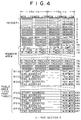
- Fig. 4 shows a format of the U-TOC sector 0.
- the sectors 0 to 32 can be provided. Namely, the sectors to be recorded correspond to the main sectors SC00 to SC1F in one cluster.
- the sector 1 and sector 4 are the areas for recording character information and the sector 2 is the area for recording the date of recording.
- the sectors 1 and 4 will be explained later and explanation of the sector 2 is omitted here.
- the U-TOC sector 0 is used as the data area in which a program such as a music piece recorded by a user and management information about the free area to which programs may be newly recorded are recorded.
- the MD controller 11 searches the free area on the disk from the U-TOC sector 0 and records the audio data to this free area. Moreover, at the time of reproducing operation, the area in which the music piece to be reproduced is recorded is discriminated from the U-TOC sector 0 and access is made to this area for the purpose of reproducing operation.
- the address of three bytes which becomes the cluster address (Cluster H) (Cluster L) and sector address (Sector) is recorded, the mode information (MODE) of one byte is moreover added to form the header.
- the address of three bytes is the address of the relevant sector itself.
- the address of the sector itself and synchronous pattern are recorded in unit of sector even in the P-TOC sector and the sector of the program area in addition to the U-TOC sector 0.
- data such as maker code, model code, track number of the first track (First TNO), track number of the last track (Last TNO), section using condition (Used sectors), disk serial number, disk ID, etc. is recorded to the predetermined byte position.
- an area for recording various pointers (P-DFA(Pointer for Defective Area), P-EMTY(Pointer for Empty Slot) , P-FRA(Pointer for Freely Area), P-TNO1 to P-TNO255) as the pointer section is also prepared.
- the 255 parts tables from (01h) to (FFh) are provided and the start address indicating the start point of a certain part, the end address indicating the end point thereof and the mode information of part are recorded in each part table. Moreover, since a part indicated in each part table is linked continuously to the other part in some cases, link information indicating the part table in which the start address and end address of the part to be linked are recorded can also be recorded.
- a part means the track section in which the data which is continuous in time is continuously recorded physically within one track.
- the address indicated as the start address or end address becomes the address indicating one or a plurality of parts forming one program.
- the part tables can be linked by providing link information and by designating the parts table to be linked, for example, with the numbers (01h) to (FFh) given to each part table.
- one part table expresses one part and the part position is managed, for the music piece formed through the linking, for example, of three parts, by the three part tables linked by the link information.
- the link information is indicated by a numerical value which is defined by the arithmetic process as the byte position in the U-TOC sector 0.
- the part table is designated as 304 + (link information) x 8 th (byte).
- the pointer P-DFA indicates a defective area on the magneto-optical disk 90 to designate the first part table in one part table or in a plurality of part tables in which the part is shown as the defective area due to existence of flaw, etc. That is, if a defective part exists, any one of (01h) to (FFh) is recorded in the pointer P-DFA and a defective part is indicated in the corresponding part table by the start and end addresses. In addition, of the other defective part exists, the other part table is designated as the link information in the part table and a defective part is also indicated in such part table. Moreover, when there is no defective part, the link information is indicated, for example, as "00h" and thereafter it is assumed that there is no link in the subsequent tables.
- the pointer P-EMPTY indicates the first part table in one or a plurality of unused part tables in the table section. When unused part tables exist, any one of (01h) to (FFh) is recorded as the pointer P-EMPTY.
- the part table is sequentially designated from the part table designated by the pointer P-EMPTY by the link information and all unused part tables are linked on the table section.
- Fig. 5 schematically shows the part management condition which will become the free area using a part table.
- This figure shows the condition that when the parts (03h)(18h)(1Fh)(2Bh)(E3h) are assumed as the free areas, this condition is also expressed by the link of the part tables (03h)(18h)(1Fh)(2Bh)(E3h), following the pointer P-FRA. It is also applied to the management mode of the defective area and unused part tables.
- the pointer P-TN01 to P-TNO255 indicates the programs such as music pieces recorded by a user on the disk 90 and the pointer P-TN01, for example, designates the part table indicating the leading part in terms of time among one or a plurality of parts in which the first track data is recorded.
- the recording area of the first track is recorded as the start address and end address in the part table indicated by the pointer P-TN01.
- each part is designated in the timing sequence in order to indicate the second track recording position.
- the other part tables are designated in the timing sequence by the link information from the part table designated by the pointer P-TN02 and thereby the part tables are linked up to the part table resulting in the link information of "00h" (profile similar to Fig. 5 explained above).
- the continuous music information can be obtained from the discrete parts and the recording using effectively the recording area can be realized by making access to such parts with the optical head 3 and magnetic head 6a at the time of reproducing the second music piece and performing the overwriting to the area of the second music piece using the data of this U-TOC sector 0.
- the area management on the disk is conducted by P-TOC for the re-programmable magneto-optical disk 90 and moreover the music pieces recorded in the recordable user area and free area can be managed by U-TOC.
- Fig. 6 shows a format of the U-TOC sector 1.
- This sector 1 is used as the data area to record the input character information when each recorded track is given the track name or when the disk is given the disk name which becomes the information indicating the name of the disk itself.
- the pointers P-TNA1 to P-TNA255 are prepared as the pointer section corresponding to each recorded track and moreover the slots of 255 units (01h) to (FFh), each unit is composed of 8 bytes, and one slot (00h) of 8 bytes are also prepared as the slot section designated by the pointers P-TNA1 to P-TNA255 to manage the character data in almost the same profile as the U-TOC sector 0 explained above.
- the character information as the disk title and track name is recorded by the ASCII code (American Standard Code for Information Interchange).
- characters input by a user corresponding to the first track are recorded.
- character input corresponding to one track may become larger than 7 bytes.
- the 8 bytes as the slot (00h) is assumed as the exclusive area for recording of the disk name and it is also assumed as the slot not designated by the pointer P-TNA(x).
- the pointer P-EMPTY can manage the unused slot even with this U-TOC sector 1.
- Fig. 7 shows the U-TOC sector 4.
- This sector 4 is assumed as the data area for recording input character information, like the sector 1 explained above, when the track recorded by a user is given the music name or when the disk is given the disk name and the format is almost the same as the sector 1 as is apparent from comparison of Fig. 7 and Fig. 6.
- this sector 4 is provided to record the code data (2-byte code) corresponding to Kanji characters or alphabets and the attribute of the character code is recorded to the predetermined byte position.
- Management of character information of this U-TOC sector 4 is performed, like the sector 1, by the pointers P-TNA1 to P-TNA255 and the slots (01h) to (FFh) of 255 units designated by the pointers P-TNA1 to P-TNA255.
- the buffer memory 13 accumulates the recording or reproducing audio data compressed by the ATRAC system during the recording/reproducing operation of the disk 90 and also holds the TOC information read from the disk 90.
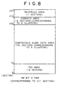
- the area format for example, shown in Fig. 8 is employed to the buffer memory 13.
- the buffer memory 13 is designed, for example, as D-RAM of 4M bits for accumulation of data corresponding to 221 sectors.
- the area of 16 sectors is set as the TOC area to store the TOC information and the area of 192 sectors is acquired as the compressed audio data area to store the recording/reproducing data. Moreover, the area of six sectors is set as the subdata area to store the subdata and the area of seven sectors is set as the reserved area.
- buffering for six clusters is performed in regard to the compressed audio and subdata.
- the character information supplied by the tuner unit 30 is stored during the recording operation as explained above but the character information read from the disk 90 and supplied to the tuner unit 30 is stored during the reproducing operation.
- the TOC sector required for the disk 90 is stored after the disk 90 is loaded, but update process of the U-TOC sector 0, sector 1, sector 2, sector 4 is once performed in the TOC area.
- FIG. 9A to 9C A frame format of the character information TDT superimposed on the audio signal as the FM multiplex broadcasting is shown in Figs. 9A to 9C.
- the real data as the frame which becomes a data unit of the character information TDT is formed of 190 packets.
- One packet is formed of 22 bytes.
- the parity packet is added to the ordinary 190 packets, one frame is formed of 272 packets.
- Fig. 9B Format of one packet(22 bytes) is shown in Fig. 9B. Namely, it is formed of the prefix information and real data.
- One format has the prefix of four bytes and data of 18 bytes, while the other format has the prefix of two bytes and data of 20 bytes.
- the service identifying (ID) code, decoding identifying (ID) code, information end code, update code, data group number and data packet number are recorded as shown in Fig. 9C.
- the tuner controller 31 can discriminate, by means of the service ID code, the kind of contents of traffic information, program information of the character information of the packet.
- the recording capacity as the subdata is 2332 bytes per 2.043 seconds as explained above.
- the packet data to be decoded not only ordinary 190 packets as the real data in one frame but also a parity packet is included and the ordinary packet among the 114 packets obtained during one cluster period, except for the parity packet, is equivalent to about 80 packets (79.3 packets in average, 81 packets in maximum).
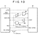
- the communication as shown in Fig. 10 is performed for the transfer of character data between the MD controller 11 and tuner controller 31.
- the character information pTDT as the reproduced data, clock SCK, clock enable SCK-EN, recording condition signal REC and reproducing synch PB-SYNC are transmitted to the tuner controller 31 from the MD controller 11.
- the character information wTDT as the recording data and the recording synch REC-SYNC are transmitted to the MD controller 11 from the tuner controller 31.
- the clock SCK, clock enable SCK-EN and recording condition signal REC are transmitted to the tuner controller 31 from the MD controller 11 and the character information wTDT as the recording data and recording synch REC-SYNC are also transmitted, based on these signals, to the MD controller 11 from the tuner controller 31.
- the character information pTDT as the reproduced data, clock SCK, clock enable SCK-EN and reproducing synch PB-SYNC are transmitted to the tuner controller 31 from the MD controller 11 and the tuner controller 31 receives these signals to perform the display operation on the display unit 38 of the character information pTDT.
- the clock SCK has, for example, the frequency of 750 kHz.
- the clock enable SCK-EN is set to "H" at the time of the recording and reproducing of the character information in order to control the process of the tuner controller 31.
- the clock SCK is masked by the clock enable SCK-EN to become effective only during the character data transfer process between the MD controller 11 and tuner controller 31. Namely, when the clock enable SCK-EN is set to "L" level, input of the clock SCK to the tuner controller 31 is masked depending on the inverter 41 and logical operation of the OR gate 42.
- the recording condition signal REC is set to "H” only when recording is performed for the disk 90 and is set to "L” when reproducing from the disk 90 is performed or stopped.
- a three-state buffer 44 is provided to the signal line of the character information wTDT as the recording data from the tuner controller 31 and it is controlled by the logical output of the AND gate 43 to the enable state only during the transfer for the recording operation. That is, the MD controller 11 accepts transfer of the character information wTDT only when the recording condition signal REC is "H" level and clock enable SCK-EN is "H" level.
- the recording synch REC-SYNC generated by the tuner controller 11 during the recording operation is the pulse of 18 ms in average, namely, the synchronous signal of packet unit of the character information.
- the MD controller 11 receives the character information wTDT transmitted with reference to the recording synch REC-SYNC.
- the reproducing synch PB-SYNC generated by the MD controller 11 during the reproducing operation is the pulse of 11.6 ms, namely, the synchronous signal of the unit corresponding to the sound group in the sector as the reproduced data.
- the tuner controller 31 receives the character information pTDT transmitted with reference to the reproducing synch PB-SYNC.
- the inverter 41, OR gate 42, AND gate 43 and three-state buffer 44 may be arranged on the communication line or the logical operations of these elements may be performed within the MD controller 11 or tuner controller 31.
- Fig. 11 shows a flowchart of the processes of the MD controller 11 and tuner controller 31 in regard to the transfer process during the recording operation
- Figs. 12A to 12G show a timing chart of the transfer process during the encoding timing of a certain cluster (N cluster) .
- N cluster a certain cluster
- the MD controller 11 sets, as the process of the step F101 of Fig. 11, the recording condition signal REC to be transmitted to the tuner controller 31 to the "H" level.
- the tuner controller 31 detects, in the step F201 of Fig. 11, that the recording condition signal REC becomes "H"
- the process of tuner controller 31 enters the recording mode and goes to the step F202 to perform the subsequent processes.
- the tuner controller 31 starts the transfer operation to the MD controller 11 of the character information as the recording mode operation.
- a pulse is output, as the recording synch REC-SYNC, to the MD controller 11 in the timing of the decoding operation of packet data.
- the MD controller 11 is waiting for the input of the pulse as the recording synch REC-SYNC in the step F102 and goes to the step F103 when input of pulse is detected to set the clock enable SCK-EN to the "H" level.
- the tuner controller 31 skips to the step F204 from the step F203 to cancel the mask of the clock SCK to be input to the tuner controller 31.
- the MD controller 11 outputs the clock SCK in the step F104.
- the output of clock SCK is composed of eight bytes in the unit of byte.
- the tuner controller 31 sequentially transmits the packet data as the character information, in the step F204, in synchronization with the clock SCK input sequentially.
- the tuner controller 31 transmits the data in which one packet is composed of 22 bytes with addition of the packet identifying (ID) code of two bytes at the starting area.
- the decoded packet is the parity packet
- the 2-byte code "8000h" is added as the packet ID code.
- the decoded packet is the ordinary packet as the real packet
- the 2-byte code "0000h” is added as the packet ID code.
- the decoded packet is the packet not including the real packet
- the 2-byte code "4000h" is added as the packet ID code.
- the packet data is superimposed as the actual character information on bytes 3 to 24 in 24 bytes, but in the case of the parity packet or packet having no data, bytes 3 to 24 in the data become all zeros.
- the tuner controller 31 must discriminate the contents of packet data, to add the packet ID code of two bytes, whether the packet is the ordinary packet or parity packet or the packet having no data, by referring to the service ID code among the data of one packet shown in Fig. 9B.
- the MD controller 11 receives, in the step F104, the packet data depending on the transfer of packet data from the tuner controller 31 in the step F204.
- the tuner controller 31 continues the process of the step F204 until it is detected in the step F205 that the clock enable SCK-EN is set to the "L" level.
- the character information of eight bytes is transmitted to the MD controller 11 side.
- the MD controller 11 confirms in the step F104 that the data of 24 bytes can be fetched. If the data is not completely fetched, the MD controller 11 returns to the step F104 to receive the data depending on the transmission of the clock SCK of eight bytes and the resultant transmission of the packet data performed in the step F204 by the tuner controller 31 side.
- the MD controller 11 goes to the step F106 to determine whether the packet data received now is the ordinary packet or not. This process is identical to that for confirming the packet ID code added to the heading two bytes of 24 bytes.
- the received packet is discriminated as the ordinary packet by the packet ID code
- packet data is assumed as the data to be recorded to the disk 90 as the subdata in the step F107.
- the 22 bytes among 24 bytes except for the packet ID code of two bytes are transferred to the buffer memory 13 and it is then supplied to the encoding/decoding unit 8 together with the audio data in the predetermined timing in order to perform the encoding as the subdata in the cluster as explained above.
- the 24 bytes per one packet including the packet ID code may be defined as the recording object. That is, it is also possible that the received 24 bytes are transferred to the buffer memory 13 to execute the recording process as the subdata.
- the packet data received in the step F106 is determined as the parity packet or packet having no data, such packet data is not processed as the data for recording. For example, such data is cleared.
- the MD controller 11 sets the clock enable SCK-EN to the "L" level in the step F108.
- the tuner controller 31 skips to the step F206 from the step F205 and then skips to the step F202 when the recording condition signal REC is still in the "H" level.
- the MD controller 11 controls the transfer period of one packet (period in which the step F204 is executed by the tuner controller 31) with the clock enable SCK-EN.
- the tuner controller 31 returns to the step F202 when the clock enable SCK-EN is set to the "L" level.
- the recording synch REC-SYNC generated in the step F202 is the timing synchronized with the character information decoding process and is the pulse having the average interval of 18 ms. Therefore, the next recording synch REC-SYNC is generated in the step F202 after about 18 ms from the time when the preceding recording synch REC-SYNC is generated.
- the MD controller 11 returns to the step F102 from the step F109 if the recording is not yet completed after the clock enable SCD-EN is set to the "L" level in the step F108 and waits for the recording synch REC-SYNC.
- the MD controller 11 When the new recording synch REC-SYNC is generated as the process in the step F202 of the tuner controller 31 after about 18 ms from the time when the preceding recording synch REC-SYNC is generated, the MD controller 11 performs the processes similar to that after the step F103. Depending on this operation, the tuner controller 31 performs the processes of the steps F203 to F205.
- the MD controller 11 Upon completion of the recording operation, the MD controller 11 goes to the step F110 from the step F109 to complete the process by setting the recording condition signal REC to the "L" level.
- the tuner controller 31 goes to the step F207 from the step F206 to complete the recording mode.
- the recording condition signal REC is set to the "L" level in the course of the transfer operation, it clears the transfer operation.
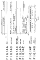
- Fig. 12A shows the timing of the encoding of cluster.
- the recording condition signal REC is set to the "H" level as shown in Fig. 12B. Namely, this signal is continuously in the "H" level during the period to reach the step F110 from the step F101.
- timing relationship between the cluster timing and recording synch REC-SYNC (namely, the signal synchronized with the decoding in the character decoding unit 35) is different in each process as shown in Fig. 12A and Fig. 12C.
- the recording synch REC-SYNC is generated in every about 18 ms.
- Figs. 12D, 12E, 12F show an enlarged packet data period.
- the pulse of recording synch REC-SYNC is generated as shown in Fig. 12D.
- the MD controller 11 sets, in the step F103, the clock enable SCK-EN to the "H" level as shown in Fig. 12E.
- the character information wTDT as the packet data in unit of 24 bytes as shown in Fig. 12E is transferred.
- the transfer is performed in units of eight bytes such as bytes 1 to 8, bytes 9 to 16 and bytes 17 to 24 in the 24 bytes.
- Fig. 12F shows the further enlarged transfer period of the 4 th byte and 5 th byte and thereby it can be understood that each bit data is transmitted in synchronization with the clock SCK of Fig. 12G.
- Figs. 12A to 12G the time length of each period as the timing for the data transfer process is indicated by ⁇ t1 to ⁇ t5 and each period is respectively defined as follow.
- the data in which one packet is formed of 24 bytes is transferred as much as 114 packets in one cluster period and as is explained with reference to Fig. 11, only the ordinary packet among the packet data transferred is defined as the recording data (subdata).
- the decoded character information can be recorded to the disk 90 simultaneously with the audio signal as the main data at the time of the air-check recording operation.
- the recording/reproducing unit 1 data is read, decoded and buffered as the reproducing operation from the disk 90 and the audio data, that is, the audio signal of the main data recorded in the past is reproduced and output from the terminal Aout.
- the character information pTDT extracted by the decoding of the subdata sector SCFF is transmitted to the tuner unit 30.
- the MD controller 11 reads the decoded character information pTDT from the buffer memory 13 and then transfers it to the tuner controller 31.
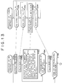
- Fig. 13 shows a flowchart of the processes by the MD controller 11 and tuner controller 31 in regard to the transfer process during the reproducing operation
- Fig. 14A shows a timing chart of the transfer process in the output timing period, namely 2.043 seconds corresponding to the period corresponding to the data of one cluster as the reading/audio reproduced output from the buffer memory 13 of a certain cluster (N cluster).
- the MD controller 11 keeps the recording condition signal REC to the "L" level for transmission to the tuner controller 31.
- the tuner controller 31 receives, during the period where the recording condition signal REC is in the "L" level, the character information pTDT transferred from the MD controller 11 depending on the input of the reproducing synch PB-SYNC from the MD controller 11.
- the MD controller 11 transmits the data as the character information pTDT in the packet data format and generates, on the occasion of transmission in every packet, the reproduction synch PB-CYNC from the start timing of the cluster in the step F151.
- the tuner controller 31 shifts to the step F252 to receive the transferred data and waits the clock enable SCK-EN to become "H" level.
- the MD controller 11 Immediately after the reproducing synch PB-SYNC is generated, the MD controller 11 goes to the step F152 to set the clock enable SCK-EN to the "H" level.
- the process of the tuner controller 31 moves to the step F253 from the step F252 and thereby the mask of the clock SCK to be input to the tuner controller 31 is canceled.
- the MD controller 11 outputs the clock SCK in the step F153.
- the clock SCK is output as many as eight bytes in byte units.
- the MD controller 11 sequentially outputs the packet data as the character information in synchronization with the clock SCK.
- the MD controller 11 transmits the data of the character information pTDT in which one packet is formed of 22 bytes after adding the packet identifying code of two bytes to the heading area of the information.
- the one packet information pTDT is completely the data corresponding to the ordinary packet. Therefore, as the format is shown in Fig. 15B, the 2-byte code of "0000h" as the packet ID code corresponding to the ordinary packet is added to the heading area of the transfer data in which one packed is formed of 24 bytes. Accordingly, the actually reproduced data as the character information is superimposed on bytes 3 to 24 in 24 bytes.
- the processing system to record the data to the disk 90 by forming the subdata based on that one packet is formed of 24 bytes including the packet ID code.
- the packet ID code "0000h” is added, as the heading two bytes, to the data (24 bytes) in unit of packet read from the subdata during the reproducing operation.
- the process to add the packet ID code as the process in the step F153 is naturally eliminated.
- the tuner controller 31 receives the packet data in the step F253. That is, the transfer data is fetched in synchronization with the supplied clock SCK.
- step F253 by the tuner controller 31 side is continued until the clock enable SCK-EN is fallen to the "L" level in the step F254.
- the character information of eight bytes is first transmitted to the side of the tuner controller 31 but the MD controller 11 confirms the end of transfer output as many as 24 bytes in the step F154. If the transfer is not yet completed, the MD controller 11 returns to the step F153 to transmit the clock SCK of eight bytes and transfer the packet data of eight bytes.
- the transfer output of 24 bytes, namely, one packet data is determined to be completed in the step F154 by repeating three times the transmission of the clock SCK of eight bytes and transferring the byte data synchronized with such clock SCK in the step F153.
- the MD controller 11 goes to the step F115 to set the clock enable SCK-EN to the "L" level.
- the tuner controller 31 returns to the step F251 from the step F254 to wait for the reproducing synch PB-SYNC.
- the MD controller 11 controls the transfer period (period in which the step F253 is executed by the tuner controller 31) of one packet with the clock enable SCK-EN.
- the MD controller 11 After the clock enable SCK-EN is set to the "L" level, if the reproducing operation is not yet completed, the MD controller 11 returns to the step F151 from the step F156 to generate the reproducing synch PB-SYNC in the predetermined timing.
- the reproducing synch PB-SYNC becomes the pulse having an interval of 11.6 ms as explained above, namely the timing synchronized with the reproducing output operation in the recording/reproducing unit 1.
- the new reproducing synch PB-SYNC is generated as the process in the step F151 and subsequently the similar process is performed from step F152. Moreover, the tuner controller 31 performs the processes of the steps F252 to F254 depending on the above process.
- the MD controller 11 terminates the process from the step F156.
- the MD controller 11 intermits the transfer in some cases.
- Fig. 14A shows the reproducing operation timing of data as the cluster and the recording condition REC is set to the "L" level during the reproducing operation as shown in Fig. 14a.
- the reproducing synch PB-SYNC is generated in every 11.6 ms from the leading area of the cluster as shown in Fig. 14C.
- Figs. 14D, 14E, 14F an enlarged packet data period is shown.
- the pulse as the reproducing synch PB-SYNC is generated as shown in Fig. 14C and subsequently, in the step F152, the clock enable SCK-EN is set to the "H" level as shown in Fig. 14D.
- transfer is performed in units of eight bytes, such as bytes 1 to 8, bytes 9 to 16 and bytes 17 to 24 in the 24 bytes.
- Fig. 14F also shows a further enlarged transfer periods of bytes 4 and 5, suggesting that each bit data is transmitted in synchronization with the clock SCK of Fig. 14G.
- Figs. 14A to 14G show the time length of each period with ⁇ t11 to ⁇ t15 as the timings in relation to the data transfer process. Each period is as indicated below.
- the character information pTDT forming one packet with 24 bytes the 79.3 packets in average obtained in one cluster period are transferred to the tuner controller 31 side.
- the tuner controller 31 causes RAM 36 to store the character information pTDT transferred as explained above and also the display unit 38 to display the data.
- the name of music piece and the other character information recorded can be used, upon confirmation, as the guide of the track name input.
- this is just suitable for edition of the audio data as the main data. Namely, track division, track erasing and track coupling can be performed freely and the displayed character information can be used as the guide for operation.
- timing chart can also be used for recording of the character information.
- the character information broadcast simultaneously with the audio information as the main data can be confirmed and a user is not required to attend the place during the recording operation to surely observe the display of character information.
- both audio information and character information of the FM multiplex broadcasting can be recorded simultaneously to the disk 90 and can also be reproduced.
- the audio data (and character information) recorded as explained above is managed on the disk 90 as one track for single recording operation.
- the area of the recording data of 60 minutes is managed as the first track in the U-TOC sector 0.
- very complicated operation is required to reproduce the broadcast content from the intermediate area.
- the track mark setting process is performed in the adequate timing during the recording operation of the audio signal and the recorded audio information and character information are appropriately divided to the tracks in the U-TOC after the recording operation.
- the track mark process is performed so that the timing to start a music piece among the programs to be recorded becomes the track dividing point.
- the timing to start a music piece in the broadcasting can be detected by monitoring the character information broadcast and decoded simultaneously.
- the audio signal demodulated as explained above is supplied to the recording/reproducing unit 1 from the tuner unit 30 and the character information decoded by the tuner unit 30 is supplied to the MD controller 11 from the tuner controller 31 for use as the subdata recording data.
- the tuner controller 31 or MD controller 11 can determined whether the character information received and decoded is the information having the particular format or not (that is, whether it is the character information having the particular character string, particular characters or particular character pattern).
- the timing that the decoded character information is determined to have the particular format as the music name information can be determined as the timing in which the music piece is started in the broadcasting.
- the music name information Since the music name information is transmitted repeatedly for several times during broadcasting of a certain music piece, it is also required to determine that the decode timing of the same music name information of the second and subsequent appearance is not the time when a music piece is started.
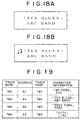
- the particular format of the music name information must correspond to all conditions of items a), b), and c) as will be understood from the display condition of Fig. 18A.
- the music name information is usually formed of the music name given the marks in the first line and the artist name not given the marks in the second line. Therefore, when the data corresponds to all conditions of items a), b) and c), it can be determined as the music name information.
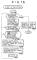
- Fig. 16 shows the process by the MD controller 11. However, for example, it is also possible to conduct the character information analyzing process in the step F303 in the side of the tuner controller 31.
- n is set to 1 in the step F301.
- the character information to be decoded is sequentially analyzed as the process of the step F303.
- This process determines whether the transferred character information is the music name information or not as explained above. That is, the character information is determined whether it is a program information or not and moreover whether it corresponds to all conditions of items a), b) and c) or not.
- the process returns to the step F302 from the step F304 and the process for the character information to be decoded is started in the step F303.
- character string of the music name information is determined in the step F305 whether it is identical or not to content of the character information determined immediately before as the music name information.
- the decode timing of the same music name information after the second transmission thereof is never matched with the time when a music piece is started. Therefore, when the data is matched with the content of the immediately preceding music name information, such data is determined as the music name information transmitted by the second and subsequent transmission. That is, the process is returned to the step F302 from the step F305, because the decode timing of such music name information is not the start timing of the relevant music piece.
- the decode timing of the music name information corresponds to the timing to start the broadcasting of the music piece having the relevant music name.
- the MD controller 11 stores, to RAM 11a, the address on the disk 90 as the track mark TM(n) when the audio signal supplied to the recording/reproducing unit 1 from the audio demodulating unit 34 is encoded as the recorded audio data and recorded to the disk 90 in the decode timing of the music name information in the step F306.
- step F307 a character string as the music name information is stored to RAM 11a as the track name TN(n) corresponding to the track mark TM(n).
- the process returns to the step F302.
- the addresses of the audio signals on the disk 90 in the timing determined as the timing to start a music piece in the broadcasting is stored as the track mark TM1, TM2, ... and the character strings of the music name information at this time are also stored as the track names TN1, TN2, ....
- the process goes from the step F302 to the step F309 and at this time, the update process of U-TOC is performed depending on the recording operation.
- U-TOC is updated to use the whole recorded data as one track.
- the U-TOC sector 0 is updated in such a manner that the entire part of recorded data is managed in separation to a plurality of tracks using the track marks TM1, TM2, ... stored in RAM11a at the time of updating and also in such a manner that the track name corresponding to the divided tracks are registered in the U-TOC sector 1 or sector 4 using the track names TN1, TN2, ... stored in RAM 11a.
- the update of U-TOC is performed for the data in the TOC area of the buffer memory 13 and thereafter re-writing of U-TOC is executed on the disk 90 at the predetermined time.
- the broadcast audio signal of single recording on the disk 90 is divided to a plurality of tracks, considering the start timing of each music piece transmitted in the broadcasting as the dividing point.
- Fig. 17A shows a program area of the disk 90 before the recording operation.
- the disk 90 is a virgin disk and the entire part of the program area is defined as the free area.
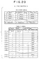
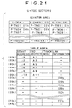
- the management condition of the U-TOC sector 0 at this time is as shown in Fig. 20.
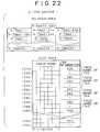
- the management condition examples of the U-TOC is shown in Figs. 20 to 22. But these are only examples.
- the pointer P-EMPTY indicating unused part table indicates, in this case, the part table (02h), and all unused part tables up to the part table (FFh) from the part table (02h) are linked by the link information.
- the music name information of each music piece is broadcast while the music pieces M1 to M4 are broadcast and are recorded to the disk 90 but the music name information of each music piece is decoded in the timing indicated by the arrow marks tm1 to tm4.
- the music name information is transmitted and decoded four times as indicated by the timing tm1
- the music name information is transmitted and decoded four times as indicated by the timing tm2.
- the first music name information of a certain music piece is determined in the steps F303 to F305 of Fig. 16 at the start timing among a plurality of timings indicated by the timings tm1 to tm4.
- the data recording address corresponding to each start timing in the timings tm1 to tm4 is stored as the track marks TM1 to TM4 as illustrated in the figure.
- the address stored as the track mark TM1 is temporarily stored as A2, the address stored as the track mark TM1 as A4, the address stored as the track mark TM3 as A6 and the address stored as the track mark TM4 as A8.
- the character strings of character information decoded at this time corresponding respectively to the track marks TM1 to TM4 are stored as the track names TN1 to TN4.
- RAM11a stores the track marks TM1 to TM4 and track names TN1 to TN4 as shown in Fig. 19.
- the character strings shown in Fig. 19 as the track names TN1 to TN4 are character strings as the music name information decoded when the track marks TM1 to TM4 are given.
- the process of Fig. 16 goes to the step F309 depending on the process that the recording operation to the program area is completed in order to update the U-TOC depending on the recording operation. During this period, however, the update process is performed depending on the track marks TM1 to TM4 and track names TN1 to TN4 as shown in Fig. 19 and the U-TOC sector 0 is rewritten, for example, to the condition of Fig. 21 from the condition of Fig. 20. Thereby, all areas recorded as shown in Fig. 17D are managed under the condition that these areas are divided to the five tracks TK1 to TK5.
- the addresses as the track marks TM1 to TM4 are defined as the starting addresses (namely, partition of track) of each track
- the first track is defined to the area starting from the recording start address (address A0 in this case) and ending to the address A1 immediately before the address A2 as the first track mark TM1.
- the second track is defined by the area starting from the address A2 of the track mark TM1 and ending by the address A2 immediately before the address A4 as the next track mark TM2.
- the third track is defined by the area starting from the address A4 of the track mark TM2 and ending at the address A5 immediately before the address A6 as the next track mark TM3.
- this section is defined as the third track TK3.
- the section starting from the address A8 of the track mark TM4 and ending at the recording end address A9 is defined as the fifth track TK5.
- the part table (06h) is designated, for example, by the pointer P-FRA and the start address A10 and end address All as the free area are recorded to the part table (06h).
- the table pointer P-EMPTY indicating the unused part table indicates the part table (07h) and unused part tables from the part table (07h) to the part table (FFh) are all linked by the link information.
- the U-TOC sector 1 or sector 4 is updated.
- the track names TN1 to TN4 stored as shown in Fig. 19 are recorded in the U-TOC sector 1 or sector 4 as the track names for the track starting from the address of the corresponding track mark.
- Fig. 22 shows the condition that the character strings as the track names TN1 to TN4 are registered to the U-TOC sector 1.
- the pointer P-TNA1 is defined as "00h" as shown in Fig. 22 and the track name is not registered.
- the character string ["MY SONG" XYZ] is stored as shown in Fig. 19 in the track name TN1 corresponding to the track mark TM1 indicating the starting point of the second track TK2, it is registered as the track name of the second track TK2 as shown in Fig. 22. That is, the pointer P-TNA2 is defined for example as "01h", moreover the part table (02h) is linked from the part table (01h), and thereby the character string ["MY SONG" XYZ] is recorded as the ASCII code to the area of seven bytes of these couple of part tables.
- the part tables (03h)(04h)(05h) are used due to the link from the pointer P-TNA3 and the character string stored as shown in Fig. 19 is recorded as the track name.
- the music name information is formed as a character string including Kanji characters and this character string is stored to RAM11a as the track names TN1, TN2, ..., it is enough that such character name is registered as the track names in the U-TOC sector 4.
- the character string including Kanji characters it is possible to generate the character string as the track names to be registered by converting the character string including Kanji characters to that of alphabets or translating such character string.
- the broadcast area of each music piece can immediately be reproduced by designating the track number to instruct the reproducing operation during the reproducing operation. Moreover, in this case, since the registered track name is also displayed, the reproducing operation can be guided and the music name can also be confirmed.
- the starting point of track can almost be located at the area near the starting point of the music piece, not resulting in any problem and if it is requested to accurately locate the starting point of track to the starting point of the music piece, it can be attained without resulting in any problem by changing the dividing point through the necessary editing operation for track dividing, linking and erasing by user.
- a certain time lag may be generated until the music name information is broadcast from the start of the broadcasting of a music piece because of the character information encoding process in the broadcasting station side.
- a certain broadcasting station always transmits the music name information with a time lag of about five seconds from the start of broadcasting of music piece.
- Time lag of several seconds will not result in any problem for the coarse track mark process only as the guide for queue during the reproducing operation, but when it is requested to raise the accuracy in regard to the track mark at the starting position of the music piece, the track mark process must be performed considering such time lag.
- the time lag is about five seconds in average
- the address of the position where the data is recorded as the audio signal at the point five seconds before the point in which the character information is decoded is set as the address of track mark TM(n).
- the particular characters are added to the particular position like the musical note marks given, for example, at the starting position of the character string in Fig. 18B.
- the receiving side can determine accurately whether the information is the music name information or not depending on existence of such particular characters and thereby adequate track mark process can be performed.
- the music piece starting point is set to the track driving point, but it is also possible that a user previously sets, for example, a keyword such as the particular character string and the track mark process is performed on the basis of such keyword. For example, a favorite artist name is registered as the particular character string and thereby the MD controller 11 sets the track mark depending on the timing where the registered particular character string is detected as the character information.
- the starting point of a music piece of a certain artist is set as the starting point of a certain track as the music piece to be recorded and a music piece of the favorite artist can easily be searched and heard from the recorded broadcast audio signals.
- the track mark is given in such timing for the purpose of track division.
- the reproduced audio signal of such track is not always the adequate point such as the starting point of the music piece but it becomes the information of the favorite artist for a user as the character information reproduced and indicated simultaneously. That is, only the wanted information among the character information recorded can easily be searched and reproduced at the time of reproducing operation.
- a minidisc system is introduced, but the present invention is not limited thereto. Namely, it is also possible to introduce, as the recording/reproducing unit 1, the system using a recording medium which can simultaneously record the audio data and subdata. Specifically, a hard disk drive system, DVD (digital video disk/digital versatile disk) system and DAT (digital audio tape) system may be employed.
- the present invention can also be applied to the system which can record the video data and character information at the same time.
- the program dividing point in regard to the main data during the relevant recording operation is set depending on the timing to detect the character information of the particular format as the character information received by the broadcasting receiving apparatus during the main data recording operation and the main data in relation to the relevant recording operation can be managed as the program divided at the preset program dividing point on the recording medium.
- the queued reproducing operation of the main data can be performed depending on the timing to decode the character information of the particular format during the reproducing operation later.
- the track mark processing is performed depending on the timing to decode the music name information, the starting point of each track can be set as the starting point of each music piece at the time of reproducing operation and the favorite music can easily and smoothly searched from the recorded audio signals.
- the convenient point track dividing can be realized at the time of reproducing operation for the recorded audio signal or to the character signal in view of remarkably improving the operation characteristic during the reproducing operation.
- the track mark process is performed by detecting the character information of particular format as music name information
- a user can enjoy the effect that the track name input corresponding to each program can be done automatically by setting the character string of the music name information as the name information corresponding to the program divided at the preset program dividing point.
- the program division can be realized at the adequate point by setting, as the program dividing point, the address of recording position on the recording medium where the audio signal received in the timing to detect the character information of the particular format is recorded as the main data.
- the program division can be realized at the adequate point without relation to time lag by setting, as the program dividing point, the address of the recording position on the recording medium where the audio signal point received in the timing preceding the predetermined time than the timing to detect the character information of particular format is recorded as the main data.
- the character information of the particular format is structured as the character information having particular character string, or character or character pattern, versatile program divisions can be realized accurately satisfying the user's needs.
Landscapes
- Engineering & Computer Science (AREA)
- Multimedia (AREA)
- Signal Processing (AREA)
- Management Or Editing Of Information On Record Carriers (AREA)
- Signal Processing For Digital Recording And Reproducing (AREA)
- Indexing, Searching, Synchronizing, And The Amount Of Synchronization Travel Of Record Carriers (AREA)
Applications Claiming Priority (2)
| Application Number | Priority Date | Filing Date | Title |
|---|---|---|---|
| JP35493997 | 1997-12-24 | ||
| JP9354939A JPH11185459A (ja) | 1997-12-24 | 1997-12-24 | 記録システム、記録装置 |
Publications (2)
| Publication Number | Publication Date |
|---|---|
| EP0926679A2 true EP0926679A2 (de) | 1999-06-30 |
| EP0926679A3 EP0926679A3 (de) | 2002-07-03 |
Family
ID=18440920
Family Applications (1)
| Application Number | Title | Priority Date | Filing Date |
|---|---|---|---|
| EP98124568A Withdrawn EP0926679A3 (de) | 1997-12-24 | 1998-12-22 | Aufzeichnungsgerät mit einer Empfangsfunktion und Aufzeichnungsgerät |
Country Status (5)
| Country | Link |
|---|---|
| US (1) | US6188662B1 (de) |
| EP (1) | EP0926679A3 (de) |
| JP (1) | JPH11185459A (de) |
| KR (1) | KR100590142B1 (de) |
| CN (1) | CN1144221C (de) |
Cited By (2)
| Publication number | Priority date | Publication date | Assignee | Title |
|---|---|---|---|---|
| EP1217768A2 (de) | 2000-12-22 | 2002-06-26 | Sony Corporation | Verfahren zum speichern oder übertragen von Zusatzinformationen und Empfänger dafür |
| EP1542232A1 (de) * | 2003-12-09 | 2005-06-15 | Sony Corporation | Informationsaufzeichnungs- und wiedergabegerät und Informationsaufzeichnungsverfahren |
Families Citing this family (16)
| Publication number | Priority date | Publication date | Assignee | Title |
|---|---|---|---|---|
| JP3552474B2 (ja) * | 1997-07-06 | 2004-08-11 | 株式会社ケンウッド | 記録媒体のタイトル入力装置 |
| JPH11260043A (ja) * | 1998-03-12 | 1999-09-24 | Pioneer Electron Corp | 情報記録装置及び情報記録再生装置並びに記録媒体 |
| JP2000163936A (ja) * | 1998-11-26 | 2000-06-16 | Sony Corp | 再生装置 |
| JP2001093226A (ja) * | 1999-09-21 | 2001-04-06 | Sony Corp | 情報通信システムおよび方法、ならびに、情報通信装置および方法 |
| JP4083957B2 (ja) * | 2000-07-10 | 2008-04-30 | パイオニア株式会社 | 記録媒体、情報記録装置及び方法、情報再生装置及び方法並びに情報記録用プログラム及び情報再生用プログラム |
| JP4214665B2 (ja) * | 2000-07-25 | 2009-01-28 | ソニー株式会社 | 再生装置 |
| JP4304888B2 (ja) * | 2000-09-04 | 2009-07-29 | ソニー株式会社 | 記録媒体、編集装置及び編集方法 |
| EP1209683A3 (de) * | 2000-11-24 | 2003-08-13 | Pioneer Corporation | Informationsaufzeichnungsgerät |
| WO2003009288A1 (en) * | 2001-07-18 | 2003-01-30 | Koninklijke Philips Electronics N.V. | Record carrier and method and recording apparatus for recording thereon |
| KR20030043299A (ko) * | 2001-11-27 | 2003-06-02 | 주식회사 엘지이아이 | 오디오 데이터와 부가 데이터간의 동기 기록 관리 및재생방법 |
| KR100563680B1 (ko) * | 2001-11-27 | 2006-03-28 | 엘지전자 주식회사 | 재기록 가능 기록매체의 오디오 가사 데이터 기록 관리 및재생방법 |
| JP2007011872A (ja) * | 2005-07-01 | 2007-01-18 | Toshiba Corp | メモリカードとその制御方法 |
| JP4377887B2 (ja) * | 2006-03-30 | 2009-12-02 | 株式会社東芝 | 映像分割装置 |
| US8260121B2 (en) * | 2006-05-02 | 2012-09-04 | Cyberlink Corp. | Systems and methods for writing data to an optical disc |
| KR100737696B1 (ko) | 2006-11-01 | 2007-07-10 | 엘지전자 주식회사 | 오디오 데이터와 부가 데이터간의 동기 기록 관리 및재생방법 |
| US8145975B2 (en) * | 2008-02-28 | 2012-03-27 | Ip Video Communications Corporation | Universal packet loss recovery system for delivery of real-time streaming multimedia content over packet-switched networks |
Family Cites Families (3)
| Publication number | Priority date | Publication date | Assignee | Title |
|---|---|---|---|---|
| JPH04246987A (ja) * | 1991-01-31 | 1992-09-02 | Sony Corp | 記録再生装置 |
| DE69420484T2 (de) * | 1993-02-04 | 1999-12-23 | Sony Corp., Tokio/Tokyo | Gerät zur magnetischen Aufzeichnung und Wiedergabe mit Aufzeichnung und Wiedergabe von übertragenen Charaktersignalen |
| US5646796A (en) * | 1993-05-10 | 1997-07-08 | Sony Corporation | Apparatus and method for recording and reproducing topic data with digital video and audio data |
-
1997
- 1997-12-24 JP JP9354939A patent/JPH11185459A/ja not_active Withdrawn
-
1998
- 1998-12-04 US US09/206,076 patent/US6188662B1/en not_active Expired - Fee Related
- 1998-12-22 EP EP98124568A patent/EP0926679A3/de not_active Withdrawn
- 1998-12-24 KR KR1019980058663A patent/KR100590142B1/ko not_active Expired - Fee Related
- 1998-12-24 CN CNB981264425A patent/CN1144221C/zh not_active Expired - Fee Related
Cited By (4)
| Publication number | Priority date | Publication date | Assignee | Title |
|---|---|---|---|---|
| EP1217768A2 (de) | 2000-12-22 | 2002-06-26 | Sony Corporation | Verfahren zum speichern oder übertragen von Zusatzinformationen und Empfänger dafür |
| EP1217768A3 (de) * | 2000-12-22 | 2007-06-27 | Sony Corporation | Verfahren zum speichern oder übertragen von Zusatzinformationen und Empfänger dafür |
| EP1542232A1 (de) * | 2003-12-09 | 2005-06-15 | Sony Corporation | Informationsaufzeichnungs- und wiedergabegerät und Informationsaufzeichnungsverfahren |
| US7400566B2 (en) | 2003-12-09 | 2008-07-15 | Sony Corporation | Method of sequentially recording programs using calculated reception ending times |
Also Published As
| Publication number | Publication date |
|---|---|
| EP0926679A3 (de) | 2002-07-03 |
| CN1144221C (zh) | 2004-03-31 |
| US6188662B1 (en) | 2001-02-13 |
| KR19990063458A (ko) | 1999-07-26 |
| CN1223438A (zh) | 1999-07-21 |
| JPH11185459A (ja) | 1999-07-09 |
| KR100590142B1 (ko) | 2006-08-30 |
Similar Documents
| Publication | Publication Date | Title |
|---|---|---|
| EP0926679A2 (de) | Aufzeichnungsgerät mit einer Empfangsfunktion und Aufzeichnungsgerät | |
| CA2250678C (en) | Reproducing apparatus, recording apparatus, and recording medium | |
| JPH07287967A (ja) | 記録方法及び記録装置 | |
| US20020041540A1 (en) | Recording medium, editing method and editing apparatus | |
| US6295267B1 (en) | Digital signal recording apparatus, recording method thereof, remote controlling apparatus for use therewith, remote controlling method thereof, and dubbing system for use therewith | |
| JP3826632B2 (ja) | 再生装置及び情報通信システム | |
| US6301203B1 (en) | Apparatus and method for reproducing main data and sub data in synchronization | |
| EP0994481B1 (de) | Wiedergabegerät und -Verfahren, Aufzeichnungsgerät und -Verfahren | |
| JPH11250633A (ja) | 記録媒体及び記録装置 | |
| JPH1173730A (ja) | 放送記録装置 | |
| US6345017B1 (en) | Reproducing apparatus capable of suppressing mechanical noise during access of sub data and main data | |
| JP3994504B2 (ja) | 編集装置 | |
| JPH08102149A (ja) | 文字情報記録装置及び文字情報出力装置 | |
| JPH08124362A (ja) | 再生装置 | |
| JPH11213631A (ja) | 編集装置 | |
| JPH11224463A (ja) | 記録装置、再生装置 | |
| JPH11213545A (ja) | 再生装置 | |
| JP3815146B2 (ja) | 再生装置及び再生方法 | |
| JPH11306739A (ja) | 受信装置 | |
| JPH0850778A (ja) | 音声記録システム | |
| JPH0855465A (ja) | 音声記録システム | |
| JPH11213544A (ja) | 再生装置、記録装置 | |
| JPH11176107A (ja) | 記録システム、放送受信装置、記録装置、再生システム、再生装置、及び文字情報出力装置 | |
| JP2001052468A (ja) | 再生装置、記録装置 | |
| JP2000076832A (ja) | データコピー方法及びデータコピー装置 |
Legal Events
| Date | Code | Title | Description |
|---|---|---|---|
| PUAI | Public reference made under article 153(3) epc to a published international application that has entered the european phase |
Free format text: ORIGINAL CODE: 0009012 |
|
| AK | Designated contracting states |
Kind code of ref document: A2 Designated state(s): AT BE CH CY DE DK ES FI FR GB GR IE IT LI LU MC NL PT SE |
|
| AX | Request for extension of the european patent |
Free format text: AL;LT;LV;MK;RO;SI |
|
| PUAL | Search report despatched |
Free format text: ORIGINAL CODE: 0009013 |
|
| AK | Designated contracting states |
Kind code of ref document: A3 Designated state(s): AT BE CH CY DE DK ES FI FR GB GR IE IT LI LU MC NL PT SE |
|
| AX | Request for extension of the european patent |
Free format text: AL;LT;LV;MK;RO;SI |
|
| 17P | Request for examination filed |
Effective date: 20021108 |
|
| AKX | Designation fees paid |
Designated state(s): DE FR GB |
|
| 17Q | First examination report despatched |
Effective date: 20030328 |
|
| STAA | Information on the status of an ep patent application or granted ep patent |
Free format text: STATUS: THE APPLICATION IS DEEMED TO BE WITHDRAWN |
|
| 18D | Application deemed to be withdrawn |
Effective date: 20100630 |