EP0926733A1 - Ensemble formant une carte comprenant un dispositif de puissance dans un boitier en plastique avec un dissipateur thermique externe soudé au dissipateur thermique interne - Google Patents
Ensemble formant une carte comprenant un dispositif de puissance dans un boitier en plastique avec un dissipateur thermique externe soudé au dissipateur thermique interne Download PDFInfo
- Publication number
- EP0926733A1 EP0926733A1 EP97830677A EP97830677A EP0926733A1 EP 0926733 A1 EP0926733 A1 EP 0926733A1 EP 97830677 A EP97830677 A EP 97830677A EP 97830677 A EP97830677 A EP 97830677A EP 0926733 A1 EP0926733 A1 EP 0926733A1
- Authority
- EP
- European Patent Office
- Prior art keywords
- heat sink
- external
- metal
- slug
- printed circuit
- Prior art date
- Legal status (The legal status is an assumption and is not a legal conclusion. Google has not performed a legal analysis and makes no representation as to the accuracy of the status listed.)
- Granted
Links
Images



Classifications
-
- H—ELECTRICITY
- H10—SEMICONDUCTOR DEVICES; ELECTRIC SOLID-STATE DEVICES NOT OTHERWISE PROVIDED FOR
- H10W—GENERIC PACKAGES, INTERCONNECTIONS, CONNECTORS OR OTHER CONSTRUCTIONAL DETAILS OF DEVICES COVERED BY CLASS H10
- H10W40/00—Arrangements for thermal protection or thermal control
- H10W40/20—Arrangements for cooling
- H10W40/22—Arrangements for cooling characterised by their shape, e.g. having conical or cylindrical projections
-
- H—ELECTRICITY
- H05—ELECTRIC TECHNIQUES NOT OTHERWISE PROVIDED FOR
- H05K—PRINTED CIRCUITS; CASINGS OR CONSTRUCTIONAL DETAILS OF ELECTRIC APPARATUS; MANUFACTURE OF ASSEMBLAGES OF ELECTRICAL COMPONENTS
- H05K3/00—Apparatus or processes for manufacturing printed circuits
- H05K3/30—Assembling printed circuits with electric components, e.g. with resistors
- H05K3/32—Assembling printed circuits with electric components, e.g. with resistors electrically connecting electric components or wires to printed circuits
- H05K3/34—Assembling printed circuits with electric components, e.g. with resistors electrically connecting electric components or wires to printed circuits by soldering
- H05K3/341—Surface mounted components
-
- H—ELECTRICITY
- H05—ELECTRIC TECHNIQUES NOT OTHERWISE PROVIDED FOR
- H05K—PRINTED CIRCUITS; CASINGS OR CONSTRUCTIONAL DETAILS OF ELECTRIC APPARATUS; MANUFACTURE OF ASSEMBLAGES OF ELECTRICAL COMPONENTS
- H05K1/00—Printed circuits
- H05K1/02—Details
- H05K1/0201—Thermal arrangements, e.g. for cooling, heating or preventing overheating
- H05K1/0203—Cooling of mounted components
-
- H—ELECTRICITY
- H05—ELECTRIC TECHNIQUES NOT OTHERWISE PROVIDED FOR
- H05K—PRINTED CIRCUITS; CASINGS OR CONSTRUCTIONAL DETAILS OF ELECTRIC APPARATUS; MANUFACTURE OF ASSEMBLAGES OF ELECTRICAL COMPONENTS
- H05K2201/00—Indexing scheme relating to printed circuits covered by H05K1/00
- H05K2201/06—Thermal details
- H05K2201/066—Heatsink mounted on the surface of the printed circuit board [PCB]
-
- H—ELECTRICITY
- H05—ELECTRIC TECHNIQUES NOT OTHERWISE PROVIDED FOR
- H05K—PRINTED CIRCUITS; CASINGS OR CONSTRUCTIONAL DETAILS OF ELECTRIC APPARATUS; MANUFACTURE OF ASSEMBLAGES OF ELECTRICAL COMPONENTS
- H05K2201/00—Indexing scheme relating to printed circuits covered by H05K1/00
- H05K2201/10—Details of components or other objects attached to or integrated in a printed circuit board
- H05K2201/10613—Details of electrical connections of non-printed components, e.g. special leads
- H05K2201/10621—Components characterised by their electrical contacts
- H05K2201/10689—Leaded Integrated Circuit [IC] package, e.g. dual-in-line [DIL]
-
- H—ELECTRICITY
- H05—ELECTRIC TECHNIQUES NOT OTHERWISE PROVIDED FOR
- H05K—PRINTED CIRCUITS; CASINGS OR CONSTRUCTIONAL DETAILS OF ELECTRIC APPARATUS; MANUFACTURE OF ASSEMBLAGES OF ELECTRICAL COMPONENTS
- H05K2201/00—Indexing scheme relating to printed circuits covered by H05K1/00
- H05K2201/10—Details of components or other objects attached to or integrated in a printed circuit board
- H05K2201/10613—Details of electrical connections of non-printed components, e.g. special leads
- H05K2201/10954—Other details of electrical connections
- H05K2201/10969—Metallic case or integral heatsink of component electrically connected to a pad on PCB
-
- Y—GENERAL TAGGING OF NEW TECHNOLOGICAL DEVELOPMENTS; GENERAL TAGGING OF CROSS-SECTIONAL TECHNOLOGIES SPANNING OVER SEVERAL SECTIONS OF THE IPC; TECHNICAL SUBJECTS COVERED BY FORMER USPC CROSS-REFERENCE ART COLLECTIONS [XRACs] AND DIGESTS
- Y02—TECHNOLOGIES OR APPLICATIONS FOR MITIGATION OR ADAPTATION AGAINST CLIMATE CHANGE
- Y02P—CLIMATE CHANGE MITIGATION TECHNOLOGIES IN THE PRODUCTION OR PROCESSING OF GOODS
- Y02P70/00—Climate change mitigation technologies in the production process for final industrial or consumer products
- Y02P70/50—Manufacturing or production processes characterised by the final manufactured product
Definitions
- the present invention relates to techniques of dissipation of the heat generated inside integrated devices encapsulated in a plastic package for assembly, on the surface of a printed circuit board.
- a first approach is that of patterning copper pad on the printed circuit onto which the internal heat sink of the power device package is soldered. In this manner the heat generated inside the device may be effectively transferred to the external world through the copper pad exploiting a spreading effect over the printed circuit board.
- holes are realized within the copper pad. These holes have their inner wall covered with a film of copper and constitute as many conductive vias for transferring heat across the thickness of the board to the other side of it where another dedicated copper pad may be patterned, on which an external metal sink may be placed or alternately contacted by the metal chassis of the apparatus.
- the metal coated holes do not cross the whole thickness of the board but reach a ground metallization layer sandwiched therein, typically in the form of a copper film, perfectly suitable to disperse the heat throughout the board.
- Another known solution consists of printed circuit boards specially realized on a relatively thick metal substrate of a thermally conductive material such as aluminum.
- the system of the invention applies to any power device wherein the metal slug (internal metal heat sink) of the power device package has at least a portion projecting out of the surface of at least one side of the package commonly a molded body of encapsulating resin.
- the internal heat sink protrudes from two opposed sides of the molded body of resin of the power device package, at the bottom of the latter, that rests on the patterned layer of soldering paste defined on the component assembly side of the board.
- the external metal heat sink is shaped so to be placed over the power device.
- the external metal heat sink has two legs that extend toward the surface of the printed circuit board along the above mentioned sides of the package, and which bear on the printed layer of soldering paste, thus defining a gap between each laterally extending part of the metal slug and the inner face side of the relative vertical leg of the external metal sink opposed to it.
- Such a small vertical gap is at least partially encroached by the liquefied eutectic alloy during the soldering phase thus soldering permanently each of the two laterally protruding parts of the internal metal slug to the opposed leg of the external heat sink placed over the device.
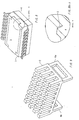
- FIG. 1 to 7 refer to a first embodiment of the invention.
- the same parts and features are identified with the same numbers in the different figures.
- an internal metal heat sink (or simply slug) 3 commonly of a highly conducting metal such as copper or nickel coated copper, onto which is bonded the silicon chip or dice of the integrated circuit, is only partially buried in the molded body of the encapsulating resin and protrudes for a certain height from the bottom face of the device 1, commonly configured for surface-assembly on a printed circuit board 7.
- the external metal heat sink 2 has a substantially flat base shaped as a rectangular frame 5, the dimensions of the central aperture 6 of the frame being coordinated with the dimensions of the protruding part of the internal metal slug 3 of the power package 1, so to accommodate such a protruding part in the aperture 6.
- the device 1 is positioned on the printed circuit board 7 after having positioned thereon the external metal heat sink 2 so that the recessed perimetral part of the bottom side surrounding the protruding metal slug 3 may rest on the four sides of the flat frame 5, whose thickness may be approximately identical to the height of the protruding part of the metal slug 3 emerging out of the bottom side of the molded resin body 4. They may both rest on the patterned layer of soldering paste 8 preventively screen printed on the surface of the board 7.
- the molten eutectic alloy 8 tends to fill at least partially, the gap 10, finally soldering the internal metal slug 3 to the flat frame 5 of the external metal heat sink.
- the metal heat sink 3 protrudes laterally out of two opposed sides of the encapsulating resin body 4 of the device 1.
- the system of the invention permits to realize assemblies that include an external metal heat sink that can be mounted on power devices surface mounted on the printed circuit board, notwithstanding the fact that the power devices be of the so-called "slug-down" type.
Landscapes
- Engineering & Computer Science (AREA)
- Manufacturing & Machinery (AREA)
- Microelectronics & Electronic Packaging (AREA)
- Cooling Or The Like Of Semiconductors Or Solid State Devices (AREA)
Priority Applications (4)
| Application Number | Priority Date | Filing Date | Title |
|---|---|---|---|
| EP97830677A EP0926733B1 (fr) | 1997-12-16 | 1997-12-16 | Ensemble formant une carte comprenant un dispositif de puissance dans un boitier en plastique avec un dissipateur thermique externe soudé au dissipateur thermique interne |
| DE69728153T DE69728153D1 (de) | 1997-12-16 | 1997-12-16 | Leiterplattenanordnung bestehend aus einem in einem Kunststoffgehäuse verpackten Leistungshalbleiterbauelement, dessen interne Wärmesenke mit einer externen Wärmesenke gelötet ist |
| US09/211,426 US6195256B1 (en) | 1997-12-16 | 1998-12-15 | Card assembly of power device in plastic package with external heat sink soldered to the internal heat sink |
| JP10356463A JPH11312769A (ja) | 1997-12-16 | 1998-12-15 | デバイス放熱用のヒートシンクアセンブリ |
Applications Claiming Priority (1)
| Application Number | Priority Date | Filing Date | Title |
|---|---|---|---|
| EP97830677A EP0926733B1 (fr) | 1997-12-16 | 1997-12-16 | Ensemble formant une carte comprenant un dispositif de puissance dans un boitier en plastique avec un dissipateur thermique externe soudé au dissipateur thermique interne |
Publications (2)
| Publication Number | Publication Date |
|---|---|
| EP0926733A1 true EP0926733A1 (fr) | 1999-06-30 |
| EP0926733B1 EP0926733B1 (fr) | 2004-03-17 |
Family
ID=8230898
Family Applications (1)
| Application Number | Title | Priority Date | Filing Date |
|---|---|---|---|
| EP97830677A Expired - Lifetime EP0926733B1 (fr) | 1997-12-16 | 1997-12-16 | Ensemble formant une carte comprenant un dispositif de puissance dans un boitier en plastique avec un dissipateur thermique externe soudé au dissipateur thermique interne |
Country Status (4)
| Country | Link |
|---|---|
| US (1) | US6195256B1 (fr) |
| EP (1) | EP0926733B1 (fr) |
| JP (1) | JPH11312769A (fr) |
| DE (1) | DE69728153D1 (fr) |
Cited By (5)
| Publication number | Priority date | Publication date | Assignee | Title |
|---|---|---|---|---|
| EP1113495A3 (fr) * | 1999-12-30 | 2001-10-24 | Texas Instruments Incorporated | Transistor de puissance monté en surface avec dissipateur thermique |
| AT409954B (de) * | 2000-04-06 | 2002-12-27 | Thyssenkrupp Presta Ag | Mehrteiliges mantelrohr für eine lenkwelle |
| EP1683701A1 (fr) | 2000-04-06 | 2006-07-26 | ThyssenKrupp Presta Aktiengesellschaft | Logement de support pour un arbre de direction |
| DE102006009812A1 (de) * | 2006-03-01 | 2007-09-06 | Beru Ag | Elektrische Schaltung mit einem oder mehreren Leistungshalbleitern |
| US11908771B2 (en) | 2021-11-12 | 2024-02-20 | Infineon Technologies Ag | Power semiconductor device with dual heat dissipation structures |
Families Citing this family (14)
| Publication number | Priority date | Publication date | Assignee | Title |
|---|---|---|---|---|
| US6483706B2 (en) * | 2000-12-22 | 2002-11-19 | Vlt Corporation | Heat dissipation for electronic components |
| US20030168730A1 (en) * | 2002-03-08 | 2003-09-11 | Howard Davidson | Carbon foam heat exchanger for integrated circuit |
| JP2007527105A (ja) * | 2003-06-06 | 2007-09-20 | ハネウエル・インターナシヨナル・インコーポレーテツド | 熱連結システムとその製造方法 |
| US6987317B2 (en) * | 2003-09-30 | 2006-01-17 | Intel Corporation | Power delivery using an integrated heat spreader |
| US7345364B2 (en) * | 2004-02-04 | 2008-03-18 | Agere Systems Inc. | Structure and method for improved heat conduction for semiconductor devices |
| US7233497B2 (en) * | 2004-10-06 | 2007-06-19 | Hewlett-Packard Development Company, L.P. | Surface mount heat sink |
| US20090323288A1 (en) * | 2008-06-30 | 2009-12-31 | Bernard Marc R | Heat sink slack storage and adaptive operation |
| US9001512B2 (en) * | 2011-05-03 | 2015-04-07 | Vishay Dale Electronics, Inc. | Heat spreader for electrical components |
| CN102299127B (zh) * | 2011-07-13 | 2013-12-11 | 台达电子企业管理(上海)有限公司 | 用于封装元件的双向散热器及其组装方法 |
| US9484280B2 (en) * | 2014-01-11 | 2016-11-01 | Infineon Technologies Austria Ag | Semiconductor device and method of manufacturing a semiconductor device |
| CA2995090A1 (fr) | 2015-08-07 | 2017-02-16 | Vishay Dale Electronics, Llc | Corps moule et dispositif electrique comportant un corps moule destine a des applications haute tension |
| US10123460B2 (en) * | 2015-11-13 | 2018-11-06 | Covidien LLP | System and method for thermal management of electronic devices |
| DE102019206523A1 (de) * | 2019-05-07 | 2020-11-12 | Zf Friedrichshafen Ag | Leistungsmodul mit gehäusten Leistungshalbleitern zur steuerbaren elektrischen Leistungsversorgung eines Verbrauchers |
| CN110729546A (zh) * | 2019-10-18 | 2020-01-24 | 大连大学 | 一种5g天线散热器 |
Citations (8)
| Publication number | Priority date | Publication date | Assignee | Title |
|---|---|---|---|---|
| US4340902A (en) * | 1977-11-18 | 1982-07-20 | Fujitsu Limited | Semiconductor device |
| JPS57117263A (en) * | 1981-01-12 | 1982-07-21 | Mitsubishi Electric Corp | Cooler for dual-in-line package type integrated circuit element |
| JPS5947750A (ja) * | 1982-09-10 | 1984-03-17 | Hitachi Ltd | 面取付型半導体装置 |
| JPS6292347A (ja) * | 1985-10-17 | 1987-04-27 | Mitsubishi Electric Corp | 半導体装置用放熱フイン |
| US4924352A (en) * | 1987-12-22 | 1990-05-08 | Societe Anonyme Dite: Alcatel Cit | Method and device for cooling an integrated circuit package |
| EP0533067A1 (fr) * | 1991-09-13 | 1993-03-24 | Nec Corporation | Empaquetage avec dissipateur de chaleur |
| US5272599A (en) * | 1993-03-19 | 1993-12-21 | Compaq Computer Corporation | Microprocessor heat dissipation apparatus for a printed circuit board |
| JPH0661635A (ja) * | 1992-08-04 | 1994-03-04 | Rohm Co Ltd | ヒートシンク付き電子部品のプリント基板への半田実装方法 |
Family Cites Families (2)
| Publication number | Priority date | Publication date | Assignee | Title |
|---|---|---|---|---|
| US4914551A (en) * | 1988-07-13 | 1990-04-03 | International Business Machines Corporation | Electronic package with heat spreader member |
| US5216283A (en) * | 1990-05-03 | 1993-06-01 | Motorola, Inc. | Semiconductor device having an insertable heat sink and method for mounting the same |
-
1997
- 1997-12-16 EP EP97830677A patent/EP0926733B1/fr not_active Expired - Lifetime
- 1997-12-16 DE DE69728153T patent/DE69728153D1/de not_active Expired - Lifetime
-
1998
- 1998-12-15 US US09/211,426 patent/US6195256B1/en not_active Expired - Lifetime
- 1998-12-15 JP JP10356463A patent/JPH11312769A/ja active Pending
Patent Citations (8)
| Publication number | Priority date | Publication date | Assignee | Title |
|---|---|---|---|---|
| US4340902A (en) * | 1977-11-18 | 1982-07-20 | Fujitsu Limited | Semiconductor device |
| JPS57117263A (en) * | 1981-01-12 | 1982-07-21 | Mitsubishi Electric Corp | Cooler for dual-in-line package type integrated circuit element |
| JPS5947750A (ja) * | 1982-09-10 | 1984-03-17 | Hitachi Ltd | 面取付型半導体装置 |
| JPS6292347A (ja) * | 1985-10-17 | 1987-04-27 | Mitsubishi Electric Corp | 半導体装置用放熱フイン |
| US4924352A (en) * | 1987-12-22 | 1990-05-08 | Societe Anonyme Dite: Alcatel Cit | Method and device for cooling an integrated circuit package |
| EP0533067A1 (fr) * | 1991-09-13 | 1993-03-24 | Nec Corporation | Empaquetage avec dissipateur de chaleur |
| JPH0661635A (ja) * | 1992-08-04 | 1994-03-04 | Rohm Co Ltd | ヒートシンク付き電子部品のプリント基板への半田実装方法 |
| US5272599A (en) * | 1993-03-19 | 1993-12-21 | Compaq Computer Corporation | Microprocessor heat dissipation apparatus for a printed circuit board |
Non-Patent Citations (6)
| Title |
|---|
| "Technique for Heat-Sinking to Lower K", IBM TECHNICAL DISCLOSURE BULLETIN., vol. 4, no. 10, March 1962 (1962-03-01), NEW YORK US, pages 53, XP002063837 * |
| BOND, G.L. ET AL: "Wrap-Around Heat Sink", IBM TECHNICAL DISCLOSURE BULLETIN., vol. 20, no. 4, September 1977 (1977-09-01), NEW YORK US, pages 1434 - 1435, XP002063836 * |
| PATENT ABSTRACTS OF JAPAN vol. 006, no. 211 (E - 137) 23 October 1982 (1982-10-23) * |
| PATENT ABSTRACTS OF JAPAN vol. 008, no. 139 (E - 253) 28 June 1984 (1984-06-28) * |
| PATENT ABSTRACTS OF JAPAN vol. 011, no. 292 (E - 543) 19 September 1987 (1987-09-19) * |
| PATENT ABSTRACTS OF JAPAN vol. 018, no. 299 (E - 1558) 8 June 1994 (1994-06-08) * |
Cited By (7)
| Publication number | Priority date | Publication date | Assignee | Title |
|---|---|---|---|---|
| EP1113495A3 (fr) * | 1999-12-30 | 2001-10-24 | Texas Instruments Incorporated | Transistor de puissance monté en surface avec dissipateur thermique |
| AT409954B (de) * | 2000-04-06 | 2002-12-27 | Thyssenkrupp Presta Ag | Mehrteiliges mantelrohr für eine lenkwelle |
| EP1683701A1 (fr) | 2000-04-06 | 2006-07-26 | ThyssenKrupp Presta Aktiengesellschaft | Logement de support pour un arbre de direction |
| DE102006009812A1 (de) * | 2006-03-01 | 2007-09-06 | Beru Ag | Elektrische Schaltung mit einem oder mehreren Leistungshalbleitern |
| DE102006009812B4 (de) * | 2006-03-01 | 2008-09-04 | Beru Ag | Montageanordnung für mehrere Leistungshalbleiter und Schaltung mit einer solchen Montageanordnung |
| US11908771B2 (en) | 2021-11-12 | 2024-02-20 | Infineon Technologies Ag | Power semiconductor device with dual heat dissipation structures |
| US12334414B2 (en) | 2021-11-12 | 2025-06-17 | Infineon Technologies Ag | Power semiconductor device with dual heat dissipation structures |
Also Published As
| Publication number | Publication date |
|---|---|
| EP0926733B1 (fr) | 2004-03-17 |
| US6195256B1 (en) | 2001-02-27 |
| DE69728153D1 (de) | 2004-04-22 |
| JPH11312769A (ja) | 1999-11-09 |
Similar Documents
| Publication | Publication Date | Title |
|---|---|---|
| EP0926733B1 (fr) | Ensemble formant une carte comprenant un dispositif de puissance dans un boitier en plastique avec un dissipateur thermique externe soudé au dissipateur thermique interne | |
| US5895973A (en) | Electronic component assembly for maintaining component alignment during soldering | |
| JP3414342B2 (ja) | 集積回路チップの実装構造および実装方法 | |
| US6188578B1 (en) | Integrated circuit package with multiple heat dissipation paths | |
| KR100231589B1 (ko) | 반도체장치 및 그 실장구조 | |
| EP0338249B1 (fr) | Empaquetage électronique | |
| US7006353B2 (en) | Apparatus and method for attaching a heat sink to an integrated circuit module | |
| KR940022808A (ko) | 반도체 디바이스 및 그 제조방법과 리이드 프레임 및 탑재기판 | |
| KR950030321A (ko) | 반도체장치 및 그 제조방법 및 기판 | |
| CA2166925A1 (fr) | Boitier de modules multipuce a empilage a gestion amelioree de la dissipation de la chaleur et de la consommation d'energie | |
| JPH06260532A (ja) | フリップチップの接続構造 | |
| US7045902B2 (en) | Circuitized substrate for fixing solder beads on pads | |
| JP4910439B2 (ja) | 半導体装置 | |
| US6034437A (en) | Semiconductor device having a matrix of bonding pads | |
| US6166435A (en) | Flip-chip ball grid array package with a heat slug | |
| EP0822595A2 (fr) | Module de type hybride | |
| JP7194542B2 (ja) | モジュール及びプリント基板 | |
| JP2905299B2 (ja) | 放熱構造および放熱板の実装方法 | |
| JP3959839B2 (ja) | 半導体装置の製造方法 | |
| US5679979A (en) | Surface mount package with heat transfer feature | |
| JPH0897336A (ja) | 半導体装置 | |
| KR0156513B1 (ko) | 반도체패키지 | |
| JPH10125833A (ja) | Bga型パッケージ実装基板及びbga型パッケージ実装方法 | |
| JP2734684B2 (ja) | 半導体素子パッケージ | |
| KR0120612Y1 (ko) | 인쇄회로기판 내장형 반도체 패키지 |
Legal Events
| Date | Code | Title | Description |
|---|---|---|---|
| PUAI | Public reference made under article 153(3) epc to a published international application that has entered the european phase |
Free format text: ORIGINAL CODE: 0009012 |
|
| AK | Designated contracting states |
Kind code of ref document: A1 Designated state(s): DE FR GB IT |
|
| AX | Request for extension of the european patent |
Free format text: AL;LT;LV;MK;RO;SI |
|
| 17P | Request for examination filed |
Effective date: 19990922 |
|
| AKX | Designation fees paid |
Free format text: AT BE CH DE LI |
|
| RBV | Designated contracting states (corrected) |
Designated state(s): DE FR GB IT |
|
| 17Q | First examination report despatched |
Effective date: 20010613 |
|
| GRAP | Despatch of communication of intention to grant a patent |
Free format text: ORIGINAL CODE: EPIDOSNIGR1 |
|
| GRAS | Grant fee paid |
Free format text: ORIGINAL CODE: EPIDOSNIGR3 |
|
| GRAA | (expected) grant |
Free format text: ORIGINAL CODE: 0009210 |
|
| AK | Designated contracting states |
Kind code of ref document: B1 Designated state(s): DE FR GB IT |
|
| PG25 | Lapsed in a contracting state [announced via postgrant information from national office to epo] |
Ref country code: FR Free format text: LAPSE BECAUSE OF FAILURE TO SUBMIT A TRANSLATION OF THE DESCRIPTION OR TO PAY THE FEE WITHIN THE PRESCRIBED TIME-LIMIT Effective date: 20040317 |
|
| REG | Reference to a national code |
Ref country code: GB Ref legal event code: FG4D |
|
| REF | Corresponds to: |
Ref document number: 69728153 Country of ref document: DE Date of ref document: 20040422 Kind code of ref document: P |
|
| PG25 | Lapsed in a contracting state [announced via postgrant information from national office to epo] |
Ref country code: DE Free format text: LAPSE BECAUSE OF FAILURE TO SUBMIT A TRANSLATION OF THE DESCRIPTION OR TO PAY THE FEE WITHIN THE PRESCRIBED TIME-LIMIT Effective date: 20040618 |
|
| PG25 | Lapsed in a contracting state [announced via postgrant information from national office to epo] |
Ref country code: GB Free format text: LAPSE BECAUSE OF NON-PAYMENT OF DUE FEES Effective date: 20041216 |
|
| PLBE | No opposition filed within time limit |
Free format text: ORIGINAL CODE: 0009261 |
|
| STAA | Information on the status of an ep patent application or granted ep patent |
Free format text: STATUS: NO OPPOSITION FILED WITHIN TIME LIMIT |
|
| EN | Fr: translation not filed | ||
| 26N | No opposition filed |
Effective date: 20041220 |
|
| GBPC | Gb: european patent ceased through non-payment of renewal fee |
Effective date: 20041216 |
|
| PGFP | Annual fee paid to national office [announced via postgrant information from national office to epo] |
Ref country code: IT Payment date: 20061231 Year of fee payment: 10 |
|
| PG25 | Lapsed in a contracting state [announced via postgrant information from national office to epo] |
Ref country code: IT Free format text: LAPSE BECAUSE OF NON-PAYMENT OF DUE FEES Effective date: 20071216 |