EP0927621A2 - Heisskanalabschnitt, insbesondere Heisskanaldüse für eine Spritzgiessmaschine oder Kunststoffspritzgiessform - Google Patents
Heisskanalabschnitt, insbesondere Heisskanaldüse für eine Spritzgiessmaschine oder Kunststoffspritzgiessform Download PDFInfo
- Publication number
- EP0927621A2 EP0927621A2 EP98123104A EP98123104A EP0927621A2 EP 0927621 A2 EP0927621 A2 EP 0927621A2 EP 98123104 A EP98123104 A EP 98123104A EP 98123104 A EP98123104 A EP 98123104A EP 0927621 A2 EP0927621 A2 EP 0927621A2
- Authority
- EP
- European Patent Office
- Prior art keywords
- hot runner
- sleeve
- flange
- current
- runner section
- Prior art date
- Legal status (The legal status is an assumption and is not a legal conclusion. Google has not performed a legal analysis and makes no representation as to the accuracy of the status listed.)
- Granted
Links
Images



Classifications
-
- B—PERFORMING OPERATIONS; TRANSPORTING
- B29—WORKING OF PLASTICS; WORKING OF SUBSTANCES IN A PLASTIC STATE IN GENERAL
- B29C—SHAPING OR JOINING OF PLASTICS; SHAPING OF MATERIAL IN A PLASTIC STATE, NOT OTHERWISE PROVIDED FOR; AFTER-TREATMENT OF THE SHAPED PRODUCTS, e.g. REPAIRING
- B29C45/00—Injection moulding, i.e. forcing the required volume of moulding material through a nozzle into a closed mould; Apparatus therefor
- B29C45/17—Component parts, details or accessories; Auxiliary operations
- B29C45/26—Moulds
- B29C45/27—Sprue channels ; Runner channels or runner nozzles
- B29C45/2737—Heating or cooling means therefor
-
- B—PERFORMING OPERATIONS; TRANSPORTING
- B29—WORKING OF PLASTICS; WORKING OF SUBSTANCES IN A PLASTIC STATE IN GENERAL
- B29C—SHAPING OR JOINING OF PLASTICS; SHAPING OF MATERIAL IN A PLASTIC STATE, NOT OTHERWISE PROVIDED FOR; AFTER-TREATMENT OF THE SHAPED PRODUCTS, e.g. REPAIRING
- B29C45/00—Injection moulding, i.e. forcing the required volume of moulding material through a nozzle into a closed mould; Apparatus therefor
- B29C45/17—Component parts, details or accessories; Auxiliary operations
- B29C45/26—Moulds
- B29C45/27—Sprue channels ; Runner channels or runner nozzles
- B29C45/30—Flow control means disposed within the sprue channel, e.g. "torpedo" construction
-
- B—PERFORMING OPERATIONS; TRANSPORTING
- B29—WORKING OF PLASTICS; WORKING OF SUBSTANCES IN A PLASTIC STATE IN GENERAL
- B29C—SHAPING OR JOINING OF PLASTICS; SHAPING OF MATERIAL IN A PLASTIC STATE, NOT OTHERWISE PROVIDED FOR; AFTER-TREATMENT OF THE SHAPED PRODUCTS, e.g. REPAIRING
- B29C45/00—Injection moulding, i.e. forcing the required volume of moulding material through a nozzle into a closed mould; Apparatus therefor
- B29C45/17—Component parts, details or accessories; Auxiliary operations
- B29C45/26—Moulds
- B29C45/27—Sprue channels ; Runner channels or runner nozzles
- B29C45/278—Nozzle tips
- B29C2045/2787—Nozzle tips made of at least 2 different materials
Definitions
- the invention relates to a hot runner section, in particular a hot runner nozzle for an injection molding machine or plastic injection mold from a centrally located heating element, which is surrounded by a radially divided sleeve is, an electrical between the heating element and the split sleeve Insulation is arranged and the heating rod and one end of the sleeves on their free ends are electrically connected to each other and the opposite ends of the free ends, ends of the sleeves facing each other are flange-like are and are suitable for feeding electrical current.
- Such nozzles are designed such as, for example, EP 0 137 888 A2, 5 shows in particular.
- Such nozzles or hot runner sections have the defect that the split outer sleeves have flange-like enlargements by a electrical insulation are separated from each other, but the insulation to the the flanges penetrating flow channel range, so that the insulation with come into contact with the melt. So that isolation is all forces and Exposed to loads resulting from the construction and operational loads, like the abruptly changing extremely high pressures of the flowing melt surrender. This is particularly disadvantageous if the melt contains solids, e.g. Contains glass fiber parts.
- the voids created by the beginning destruction of the insulating layers are filled in by the melt. This creates dead spaces and makes them more difficult Color and material changes when such changes become necessary.
- the gaps penetrating into the gaps resulting from the destruction of the insulation Melt acts on the free surfaces of the flanges and presses them apart so that the melt can penetrate. This can lead to uselessness the nozzle.
- a first sleeve is electrical is surrounded by a jacket flange, the flange of which is the second End face facing sleeve integrally, in particular by soldering to the End face of the flange of the second sleeve is connected, wherein in the area of soldered the flanges with at least one in the direction of flow penetrating flow channel are equipped, the wall in the area the flange is formed exclusively from the metal material of the flanges.
- the object is achieved in that the Flange substantially parallel to the longitudinal axis of the hot runner nozzle at least one Has passage opening for the melt, the wall over the entire Length of the passage opening consists exclusively of metallic material.
- the entire length of the passage opening continuously formed from the same material is formed from the same material.
- the plastic injection mold shown in Figure 1 has a sprue bushing 1 for the machine nozzle through which the melt enters a distribution channel 2, in which a heating wire 3 arranged to maintain the temperature of the melt is. Via the distribution channel 2, the melt reaches heatable nozzles 4 and Outlet openings 5 into the mold cavities 6. The mold is opened in level 7, in order to be able to remove the moldings by means of the ejectors 8.
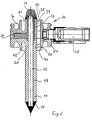
- FIG. 2 shows a nozzle denoted by 10, which is generally identified by 4 in FIG. 1 has been.
- This nozzle is formed from a central heating conductor 12 which is connected to its free ends 13 are electrically connected to the free end 16 of a first sleeve 17 is, the heating conductor 12 and the sleeve over the common length are electrically isolated from each other.
- the heating conductor 12 is at its other free end 14 with the free End 15 of a second sleeve 18 electrically connected, the heating conductor 12 and the sleeve 18 also electrically from one another over the common length section are isolated.
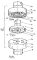
- FIG. 3 shows a kind of exploded view the essential individual parts, which are identified overall as Fig. 3.
- FIG. 3b shows the sleeve 17 in a perspective view.
- This sleeve is provided near one end with current bridges 22 which connect the sleeve with a distributor ring 23 connect.
- the distributor ring has a thread 24, which with a connecting means 25 shown in Fig. 2, e.g. a plug connection 25 connected is.
- the one or more pieces from the elements sleeve 17, current bridges 22 and Distributor ring 23 formed component 26 is in accordance with its contour in recesses 27, 28, 29 of the jacket flange 30 embedded in an electrically insulated manner.
- Between Current bridges 22 have openings 31 formed by walls Record 32 flow channels 33 formed. Penetrate these flow channels the jacket flange and open at flow channels 34 which the flange 35th penetrate.
- flow channels 38 (FIGS. 2 and 4) which are separated from the Melt entry 39 up to the melt exit exclusively from metallic walls be limited.
- circumferential grooves are to be designed at the melt inlet and melt outlet 41,42 trained to counteract the pressure loss.
- Figure 4 shows a further embodiment of the invention, which explains that the flow channels in the area of the current bridges 22a and the distributor ring 23a do not have to be an integrated part of the jacket flange 30a, but independently manufactured Channel sections 43 can be. Also in this embodiment in the finished state of the nozzle, a flow channel 38a is formed, which exclusively is formed by metallic walls. According to this embodiment is the end face 44 of the jacket flange 30a with the end faces 45 metallically connected and the end faces 46 with the end faces 47 of the flange 48.
- the channel sections 43, the flanges 30a and / or 48 penetrate all or part of the length. In this case it is a recess 49 corresponding to the contour of the channel sections 43, which is shown in FIG. 4c is indicated by dashed lines.
- FIG. 5 Another embodiment is shown in FIG. 5.
- This illustration is also a kind of exploded illustration and shows that a current bridge 22b can also be equipped in a simple embodiment.
- the current bridge is embedded in the jacket flange 30b in an electrically insulated manner based on the exemplary embodiment according to FIG. 3.
- This exemplary embodiment has the advantage of forming an almost circumferentially closed through-flow channel 50, 51, which is only interrupted by an area for the passage of the current bridge 22b and which is electrically connected to the connecting means 25 according to FIG. 1.
- the previously described embodiments have proven to be particularly advantageous in practice. This should not mean that the invention is limited to this.
- FIG. 6 shows a nozzle denoted by 10, which is generally identified by 4 in FIG. 1 has been.
- This nozzle is formed from a central heating conductor 12 which is connected to its free ends 13 with the free ends 16 of a first sleeve 17 electrically is connected, the heating conductor 12 and the sleeve over the common length section are electrically isolated from each other.
- the heating conductor 12 is at its other free end 14 with the free End 15 of a second sleeve 18 electrically connected, the heating conductor 12 and the sleeve 18 is also isolated from one another over the common length section are.
- a component which is connected to the sleeve 17, 18 and has a larger diameter educated is in one or more pieces.
- a flange 21 is formed on the sleeve 18.
- Adjacent the sleeve 18 is in the flange 21 at least one lengthwise penetrating passage opening 55 and at least one web 28, but preferably at least two through openings and at least two webs are formed, so that the melt can flow through the passage openings.
- the webs have channels 60 which define the flange 21 from the outer lateral surface 84 of the flange to the inner bore 86 of the sleeve 18 traverse radially.
- the channels cross one in the face of the flange trained, completely or partially circumferential annular groove 85, in the assembled Condition a current distributor to the flange is electrically insulated.
- In the Channels are arranged electrically isolated bridges 61, one electrically Form a conductive connection between the power distributor 62 and the sleeve 17.
- a circuit is thus formed which leads to the following stations.
- the electrical connection means 25 is preferably designed as a plug or screw contact and is used for connection to the power supply cables or the like.
- the connecting means is electrically connected to the current distributor, via which the current flows through current bridges connected to it, which are electrically connected to the sleeve 17.
- the sleeve is electrically conductively connected at its free end 16 to the free end 13 of the heating conductor 12.
- the other end 14 of the heating conductor is connected to the end 15 of the second sleeve 18, which in turn is connected to the flange, so that the current can flow off to ground.
- FIG. 8 shows the components mentioned according to the embodiment according to FIG. 6.
- the Current bridges designed as a screw body 74, which consists of a cylindrical part 75, which is followed by a threaded portion 73.
- the Sleeve provided opposite end 76 of the current bridge can be a head 77 with a slot or the like be designed to engage a turning tool.
- the current bridges are threaded into corresponding threaded bores 78 of the power distributor screwed in with the same torques. This creates same contact pressures on all current bridges due to the elastic deformability of the power distributor are favored.
- Figure 9 shows another exemplary embodiment.
- the sleeve 17a is of a substantially semicircular power distributor 62a, wherein in In this case, two current bridges 53a are provided, which are in at the free ends of the semicircular power distributor arranged threaded holes 78 can be screwed are and at their end facing the sleeve with a conical Tip 79 are equipped in the correspondingly conical recesses 80 intervene.
- the current bridge is also in this exemplary embodiment elastically deformable, so that a corresponding when screwing in the current bridges Contact pressure arises.
- the interlocking of Tip 79 and recess 80 set the sleeve and the current bridge to each other.
- FIG. 10 shows a further exemplary embodiment in which the sleeve 17b is formed eccentrically in the contact area of the current bridges 53b.
- the current bridges can have any cross section.
- Figure 11 shows an embodiment in which the current bridges 53c between the sleeve 17c and the power distributor 62c can be wedged by the Power distributor with an inner surface inclined at an acute angle to the longitudinal axis 59 83 is equipped and the axial displacement in the direction of arrow 82 Wedging occurs.
- the current bridges are also experienced in this exemplary embodiment due to the elastic deformability of the power distributor, the required contact pressure.
- FIG. A flange 21d can be seen, of which a part of the sleeve 18d can be seen, and the outer wall 87, which delimits the annular groove 85 in FIGS. 6 and 7 to the outside. Further details are not shown for a better overview.
- the current distributor 62d no longer has the additional one Task to press the current bridges against the sleeve 17d, only the Task to direct the current to the current bridges 53d.
- the contact pressure on the Current bridges to the sleeve are e.g. through a in a threaded bore 91 Wall 87 screwed screw 92 or the like. exercised, the threaded holes 91 are formed in tab 88 cut out of the wall, so are resilient to a limited extent. It is irrelevant whether the Free cutting through parallel grooves 88 or angular ones Grooves 90 takes place. It is also within the scope of the invention to dispense with the separating grooves and in front of the screw 93 a resilient means 71, e.g. to arrange a disc spring, to make the contact pressure elastic.
- the free ends 79, 84 of the current bridges are cohesively, e.g. by Solder to connect to the corresponding contact surfaces of the sleeve 17. This creates a good contact.
- One way such a connection is to be produced, using appropriate solders and the like. the heater impulsed with a higher current than the normal one Operating current in order to generate the heat necessary for the soldering process.
Landscapes
- Engineering & Computer Science (AREA)
- Manufacturing & Machinery (AREA)
- Mechanical Engineering (AREA)
- Moulds For Moulding Plastics Or The Like (AREA)
- Injection Moulding Of Plastics Or The Like (AREA)
- Resistance Heating (AREA)
Abstract
Description
- Figur 1
- die Teilansicht einer Kunststoffspritzgießform im Schnitt,
- Figur 2
- eine Düse in Schnittdarstellung,
- Figur 3
- eine perspektivische Explosionsdarstellung der wichtigsten Bauteile,
- Figur 4
- eine abgewandeltes Ausführungsbeispiel einer Düse nach Fig. 3,
- Figur 5
- die wichtigsten Bauteile eines weiteren Ausführungsbeispieles in perspektivischer Explosionsdarstellung,
- Figur 6
- eine weitere Ausführungsform einer elektrisch betriebenen Heißkanaldüse im Schnitt,
- Figur 7
- eine Schnittdarstellung durch die Heißkanaldüse gemäß der Linie II-II in Fig. 6,
- Figuren 8 bis 11
- perspektivische Ansichten von Einzelteilen der Heißkanaldüse von jeweils anderen Ausführungsbeispielen,
- Figur 12
- eine Darstellung eines weiteren Ausführungsbeispieles in Explosionsdarstellung.
Es liegt im Rahmen der Erfindung, einen dünnwandigen Stabilisierungssteg 52 in einem der beiden der Flansch 30,48 vorzusehen. Die zuvor beschriebenen Ausführungsformen haben sich in der Praxis als besonders vorteilhaft erwiesen. Dieses soll nicht bedeuten, daß sich die Erfindung darauf beschränkt.
Das Verbindungsmittel ist mit dem Stromverteiler elektrisch verbunden, über den der Strom durch mit ihm verbundene Strombrücken, die mit der Hülse 17 elektrisch verbunden sind, fließt.
Die Hülse ist an ihrem freien Ende 16 mit dem freien Ende 13 des Heizleiters 12 elektrisch leitend verbunden. Das andere Ende 14 des Heizleiters ist mit dem Ende 15 der zweiten Hülse 18 verbunden, die ihrerseits mit dem Flansch verbunden ist, so daß der Strom gegen Masse abfließen kann.
Vor dem Montagevorgang, bei dem das freie Ende 13 des Heizleiters 12 mit dem freien Ende 16 der Hülse 17b verbunden wird, wird die Hülse so verdreht, daß die exzentrischen Flächen 81 die Strombrücken 53b zwischen sich und dem Stromverteiler 62b einspannen.
An der äußeren Wandung 87 des Flansches sind drei verschiedene Ausführungsformen des Flansches zur Erzielung eines elastischen Kontaktdruckes der Strombrücken an der Hülse 17d dargestellt.
Claims (24)
- Heißkanalabschnitt, insbesondere Heißkanaldüse für eine Spritzgießmaschine oder Kunststoffspritzgießform, bestehend aus einem zentral angeordneten Heizstab, der von einer radial geteilten Hülse umgeben ist, wobei zwischen dem Heizstab und der geteilten Hülse eine elektrische Isolierung angeordnet ist und der Heizstab und jeweils ein Ende der Hülsen an ihren freien Enden elektrisch miteinander verbunden sind und die den freien Enden gegenüberliegenden, aufeinander zu gerichteten Lenden der Hülsen flanschartig ausgebildet sind und zur Einspeisung von elektrischem Strom geeignet sind,
dadurch gekennzeichnet, daß
eine erste Hülse (17) elektrisch isoliert von einem Mantelflansch (30,30a,30b) umfaßt ist, dessen dem Flansch (21) der zweiten Hülse (18) zugewandte Stirnfläche stoffschlüssig, insbesondere durch Verlöten mit der Stirnfläche des Flansches (21) der zweiten Hülse verbunden ist, wobei im Bereich der verlöteten Flächen die Flansche mit mindestens einem sie in Strömungsrichtung durchdrigenden Durchströmkanal (38,38a) ausgestattet sind, dessen Wandung im Bereich der Flansche ausschließlich von metallischem Werkstoff gebildet wird. - Heißkanalabschnitt, insbesondere Heißkanaldüse für eine Spritzgießmaschine oder Kunststoffspritzgießform nach Anspruch 1, dadurch gekennzeichnet, daß die Hülse (17) an ihrem den Flansch (21) zugewandten Ende mindestens eine nach außen weisende Strombrücke (22,22a,22b) aufweist, die mit einem Verbindungsmittel (25) verbunden ist.
- Heißkanalabschnitt, insbesondere Heißkanaldüse für eine Spritzgießmaschine oder Kunststoffspritzgießform nach Anspruch 1 und 2, dadurch gekennzeichnet, daß die Strombrücke eine elektrische Verbindung zwischen der Hülse (17) und einem ganz oder teilweise umlaufenden Verteilerring (23,23a) bilden und daß der Verteilerring mit dem Verbindungsmittel (25) elektrisch verbunden ist.
- Heißkanalabschnitt, insbesondere Heißkanaldüse für eine Spritzgießmaschine oder Kunststoffspritzgießform nach einem der vorhergehenden Ansprüche, dadurch gekennzeichnet, daß der Außenmantel der Hülse (17) und der Innendurchmesser des Verteilerringes und seitliche Flächen der Strombrücken Durchbrechungen (31) bilden, durch die die den Mantelflansch (30) und den Flansch (21) der Hülse (18) verbindende Durchströmkanäle (33), mit ihren Wandungen (32) hindurchragen.
- Heißkanalabschnitt, insbesondere Heißkanaldüse für eine Spritzgießmaschine oder Kunststoffspritzgießform nach Anspruch 4, dadurch gekennzeichnet, daß die Ausnehmung (27,28,29) im Mantelflansch (30) der Form von Hülse (17), Strombrücke (22) und Verteilerring (23) entsprechen, wobei zwischen den sich gegenüberliegenden Flächen eine elektrische Isolierung angeordnet ist.
- Heißkanalabschnitt, insbesondere Heißkanaldüse für eine Spritzgießmaschine oder Kunststoffspritzgießform nach Anspruch 1, dadurch gekennzeichnet, daß der Mantelflansch (30), die Hülse (17), die Strombrücke (22) und den Verteilerring (23) bis auf die dem Flansch (21) zugewandten Flächen nahezu vollständig umschließt.
- Heißkanalabschnitt, insbesondere Heißkanaldüse für eine Spritzgießmaschine oder Kunststoffspritzgießform nach einem oder mehreren der Ansprüche, dadurch gekennzeichnet, daß eine Endkappe die freien Enden (13) und (16) umschließt.
- Heißkanalabschnitt, insbesondere Heißkanaldüse für eine Spritzgießmaschine oder Kunststoffspritzgießforrn nach Anspruch 1, dadurch gekennzeichnet, daß die Kanalbschnitte (43) als separate Bauteile ausgeführt sind und ihre Außenkontur der Kontur der Durchbrechungen (31) entspricht, wobei die sich benachbarten Flächen elektrisch zueinander isoliert sind.
- Heißkanalabschnitt, insbesondere Heißkanaldüse für eine Spritzgießmaschine oder Kunststoffspritzgießform nach Anspruch 8, dadurch gekennzeichnet, daß die Stirnflächen (45,46) Kanalabschnitte (43) mit den benachbarten Flanschen (30,48) stoffschlüssig, insbesondere durch Löten miteinander verbunden sind.
- Heißkanalabschnitt, insbesondere Heißkanaldüse für eine Spritzgießmaschine oder Kunststoffspritzgießform bestehend aus einem zentral angeordneten Heizstab, der von einer radial geteilten Hülse umgeben ist, wobei zwischen dem Heizstab und der geteilten Hülse eine elektrische Isolierung angeordnet ist und der Heizstab und jeweils ein Ende der Hülsen an ihren freien Enden elektrisch miteinander verbunden sind und die aufeinander zu gerichteten Enden der Hülsen flanschartig ausgebildet und zur Einspeisung von elektrischem Strom geeignet sind, dadurch gekennzeichnet, daß der Flansch (21,21d) im wesentlichen parallel zur Längsachse der Heißkanaldüse mindestens eine Durchtrittsöffnung (55) für die Schmelze aufweist, deren Wandung über die gesamte Länge der Durchtrittsöffnung ausschließlich aus metallischem Werkstoff besteht.
- Heißkanalabschnitt nach Anspruch 10, dadurch gekennzeichnet, daß die Durchtrittsöffnung (55) radial ausgebildet und von einem Steg (58) unterbrochen ist.
- Heißkanalabschnitt nach Anspruch 10 oder 11, dadurch gekennzeichnet, daß mindestens zwei Durchtrittsöffnungen (55) ausgebildet sind, die von Stegen (58) getrennt sind.
- Heißkanalabschnitt nach Anspruch 11 oder 12, dadurch gekennzeichnet, daß zwischen den im Abstand zueinander angeordneten Durchtrittsöffnungen (55) Stege (58) ausgebildet sind, in denen senkrecht zur Längsachse (59) verlaufende Kanäle (60) angeordnet sind, die elektrisch isoliert Strombrücken (61) aufnehmen, die einerseits mit der Hülse (17) und andererseits mit dem Stromverteiler (62) leitend verbunden sind.
- Heißkanalabschnitt nach Anspruch 13, dadurch gekennzeichnet, daß die Strombrücken (61) schraubenartig ausgebildet sind und mit ihrem Gewinde (73) in einem im radialen Abstand zur Hülse (17) angeordneten, diese ganz oder teilweise umgebenden Stromverteiler (62) eingeschraubt sind und das freie Ende (72) der Strombrücken an der Hülse, einen elektrischen Kontakt bildend, anliegen.
- Heißkanalabschnitt 14, dadurch gekennzeichnet, daß der die Hülse (17) im Abstand umgebende Stromverteiler (62) durch das Einschrauben der Strombrücken elastisch verformbar ist und hierdurch die Strombrücken kraftschlüssig gegen den Heizkörper gepreßt werden.
- Heißkanalabschnitt nach Anspruch 13, dadurch gekennzeichnet, daß die den Strombrücken (53b) zugewandte Kontakt- und Mantelfläche (66) der Hülse (17b) exzentrisch ausgebildet ist durch Verdrehen der Hülse relativ zum Stromverteiler die Strombrücken zwischen Hülse (17b) und Stromverteiler (53b) elastisch verspannbar sind.
- Heißkanalabschnitt nach Anspruch 13, dadurch gekennzeichnet, daß die der Hülse (17c) zugewandte Innenfläche (83) des Stromverteilers (62c) im spitzen Winkel zur Längsachse (59) der Heißkanaldüse verläuft durch axiales Verschieben des Stromverteilers relativ zur Hülse, die Strombrücken zwischen dem Heizkörper und dem Stromverteiler verkeilbar sind.
- Heißkanalabschnitt nach Anspruch 13, dadurch gekennzeichnet, daß die dem Stromverteiler zugewandte Außenfläche, der Hülse im spitzen Winkel zur Längsachse (59) der Heißkanaldüse verläuft und durch axiales Verschieben des Stromverteilers relativ zum Stromverteiler, die Strombrücken zwischen dem Heizkörper und dem Stromverteiler verkeilbar sind.
- Heißkanalabschnitt nach Anspruch 13, dadurch gekennzeichnet, daß der Stromverteiler durch seine elastische Verformbarkeit den Kontaktdruck herbeiführt.
- Heißkanalabschnitt nach Anspruch 13, dadurch gekennzeichnet, daß Strombrücken im Stromverteiler elektrisch leitend gelagert sind, aus dem Flansch freigeschnittene Wandteile Gewindebohrungen aulweisen, in die mit den Strombrücken fluchtende Schrauben einschraubbar sind und die durch ihre Einschraubtiefe den Kontaktdruck bestimmen.
- Heißkanalabschnitt nach Anspruch 10, dadurch gekennzeichnet, daß die äußere Wandung des Flansches (21d) eine Gewindebohrung (91) aufweist, die eine Gewindeschraube (93) auffnimmt, zwischen der Schraube und der Strombrücke ein federelastisches Mittel (71), z.B. eine Tellerfeder angeordnet ist.
- Heißkanalabschnitt nach Anspruch 21, dadurch gekennzeichnet, daß zwischen den Berührungsflächen (95) der Schrauben und den Strombrücken elektrisch isolierende Mittel vorgesehen sind.
- Heißkanalabschnitt nach einem oder mehreren der vorherigen Ansprüche, dadurch gekennzeichnet, daß die freien Enden der Strombrücken stoffschlüssig mit den korrespondierenden Kontaktflächen der Hülse (17) verbunden sind.
- Heißkanalabschnitt nach Anspruch 10, dadurch gekennzeichnet, daß die gesamte Länge der Durchtrittsöffnung (55) ununterbrochen vom gleichen Werk stoff gebildet wird.
Applications Claiming Priority (4)
| Application Number | Priority Date | Filing Date | Title |
|---|---|---|---|
| DE19758322A DE19758322B4 (de) | 1997-12-31 | 1997-12-31 | Elektrisch betriebenes Heizelement |
| DE19758322 | 1997-12-31 | ||
| DE19758323A DE19758323B4 (de) | 1997-12-31 | 1997-12-31 | Heißkanalabschnitt, insbesondere Heißkanaldüse für eine Spritzgießmaschine oder Kunststoffspritzgießform |
| DE19758323 | 1997-12-31 |
Publications (3)
| Publication Number | Publication Date |
|---|---|
| EP0927621A2 true EP0927621A2 (de) | 1999-07-07 |
| EP0927621A3 EP0927621A3 (de) | 2000-05-17 |
| EP0927621B1 EP0927621B1 (de) | 2004-10-27 |
Family
ID=26042904
Family Applications (1)
| Application Number | Title | Priority Date | Filing Date |
|---|---|---|---|
| EP98123104A Expired - Lifetime EP0927621B1 (de) | 1997-12-31 | 1998-12-03 | Heisskanalabschnitt, insbesondere Heisskanaldüse für eine Spritzgiessmaschine oder Kunststoffspritzgiessform |
Country Status (9)
| Country | Link |
|---|---|
| US (1) | US6146126A (de) |
| EP (1) | EP0927621B1 (de) |
| JP (1) | JPH11245268A (de) |
| AT (1) | ATE280666T1 (de) |
| CA (1) | CA2257326C (de) |
| DE (3) | DE19758323B4 (de) |
| DK (1) | DK0927621T3 (de) |
| ES (1) | ES2227761T3 (de) |
| PT (1) | PT927621E (de) |
Cited By (1)
| Publication number | Priority date | Publication date | Assignee | Title |
|---|---|---|---|---|
| CN105437939A (zh) * | 2014-08-14 | 2016-03-30 | 丹阳市利旺车辆部件有限公司 | 汽车遮阳罩成型工艺 |
Families Citing this family (3)
| Publication number | Priority date | Publication date | Assignee | Title |
|---|---|---|---|---|
| ITPN20000025A1 (it) * | 2000-04-20 | 2001-10-20 | Sipa Spa | Ugello di iniezione di sostanza plastica |
| CN103386740A (zh) * | 2012-05-08 | 2013-11-13 | 昆山夏福特五金电子科技有限公司 | 一种新型的塑胶模具热流道装置 |
| CN102922682A (zh) * | 2012-11-07 | 2013-02-13 | 凡嘉科技(无锡)有限公司 | 热流道模具结构 |
Family Cites Families (5)
| Publication number | Priority date | Publication date | Assignee | Title |
|---|---|---|---|---|
| NL7804984A (nl) * | 1978-05-09 | 1979-11-13 | Beek Ter Hengelo Bv | Inwendig verwarmbaar mondstuk met een deelbaar huis en een deelbare kern. |
| CA1206311A (en) * | 1983-09-12 | 1986-06-24 | Jobst U. Gellert | Injection molding system having an insulation sleeve |
| DE3337803C2 (de) * | 1983-10-18 | 1986-07-10 | Herbert Dipl.-Ing. 3559 Allendorf Günther | Heißkanalsystem für Spritzgießvorrichtungen |
| US4902219A (en) * | 1986-01-08 | 1990-02-20 | Fast Heat Element Manufacturing Company, Inc. | Plastic injection molding system with multiple tip torpedo heater |
| CA1265916A (en) * | 1988-09-30 | 1990-02-20 | Jobst Ulrich Gellert | Method of manufacture of an electrical terminal on an injection molding nozzle |
-
1997
- 1997-12-31 DE DE19758323A patent/DE19758323B4/de not_active Expired - Lifetime
- 1997-12-31 DE DE19758322A patent/DE19758322B4/de not_active Expired - Lifetime
-
1998
- 1998-12-03 PT PT98123104T patent/PT927621E/pt unknown
- 1998-12-03 DE DE59812172T patent/DE59812172D1/de not_active Expired - Fee Related
- 1998-12-03 DK DK98123104T patent/DK0927621T3/da active
- 1998-12-03 EP EP98123104A patent/EP0927621B1/de not_active Expired - Lifetime
- 1998-12-03 AT AT98123104T patent/ATE280666T1/de not_active IP Right Cessation
- 1998-12-03 ES ES98123104T patent/ES2227761T3/es not_active Expired - Lifetime
- 1998-12-30 CA CA002257326A patent/CA2257326C/en not_active Expired - Lifetime
- 1998-12-31 US US09/223,946 patent/US6146126A/en not_active Expired - Fee Related
-
1999
- 1999-01-04 JP JP11000083A patent/JPH11245268A/ja not_active Withdrawn
Cited By (2)
| Publication number | Priority date | Publication date | Assignee | Title |
|---|---|---|---|---|
| CN105437939A (zh) * | 2014-08-14 | 2016-03-30 | 丹阳市利旺车辆部件有限公司 | 汽车遮阳罩成型工艺 |
| CN105437939B (zh) * | 2014-08-14 | 2018-02-06 | 丹阳市利旺车辆部件有限公司 | 汽车遮阳罩成型工艺 |
Also Published As
| Publication number | Publication date |
|---|---|
| CA2257326C (en) | 2007-08-21 |
| EP0927621B1 (de) | 2004-10-27 |
| EP0927621A3 (de) | 2000-05-17 |
| ES2227761T3 (es) | 2005-04-01 |
| DE19758322A1 (de) | 1999-07-01 |
| DE19758323B4 (de) | 2006-05-04 |
| PT927621E (pt) | 2005-01-31 |
| ATE280666T1 (de) | 2004-11-15 |
| DK0927621T3 (da) | 2005-01-24 |
| DE19758323A1 (de) | 1999-07-01 |
| US6146126A (en) | 2000-11-14 |
| DE59812172D1 (de) | 2004-12-02 |
| DE19758322B4 (de) | 2008-09-18 |
| JPH11245268A (ja) | 1999-09-14 |
| CA2257326A1 (en) | 1999-06-30 |
Similar Documents
| Publication | Publication Date | Title |
|---|---|---|
| DE2938832C2 (de) | ||
| EP2177339A1 (de) | Spritzgiessdüse | |
| EP2182529B1 (de) | Aluminium-Lastwiderstand | |
| EP0147736A2 (de) | Gehäuseabschnitt für eine Doppelschneckenwellenmaschine | |
| EP2032329B1 (de) | Formnestkavität mit mäanderförmigem kühlkanal | |
| DE2539785C3 (de) | Heißkanalspritzdüse | |
| EP2032330A1 (de) | Formnestkavität mit entkoppelter kühlkanalführung | |
| DE4127035A1 (de) | Heisskanalduese | |
| DE29610268U1 (de) | Heißkanaldüse | |
| DE10024625B4 (de) | Formnest für die Kunststoffverarbeitung | |
| EP0927621B1 (de) | Heisskanalabschnitt, insbesondere Heisskanaldüse für eine Spritzgiessmaschine oder Kunststoffspritzgiessform | |
| DE19854932C2 (de) | Vakuum-Außenkalibrierung | |
| EP0992332B1 (de) | Heisskanalverschluss | |
| DE10020218B4 (de) | Montageeinheit aus einem Bauteil und mindestens einer gewindeformenden Schraube | |
| DE3036498A1 (de) | Kunststoffprofilscharnier fuer schaltuschranktueren | |
| DE2924321A1 (de) | Oeldynamische einrichtung, insbesondere schmiereinrichtung | |
| DE202020102063U1 (de) | Spannbare elektrische Heizvorrichtung | |
| DE69118336T2 (de) | Schmelzeverteilerblock für mehrere Formhöhlungen | |
| EP2209601A2 (de) | Spritzgiessdüse | |
| DE102015008578B4 (de) | Heißkanaldüse | |
| DE3640620C2 (de) | ||
| DE69301263T2 (de) | Beheizte Spritzgiessdüse für mehrere Formhöhlungen | |
| DE8703191U1 (de) | Heißkanal zur Verarbeitung von Kunststoffen nach dem Spritzgußverfahren | |
| DE3523281C2 (de) | ||
| EP1846215A1 (de) | Spritzgiessvorrichtung |
Legal Events
| Date | Code | Title | Description |
|---|---|---|---|
| PUAI | Public reference made under article 153(3) epc to a published international application that has entered the european phase |
Free format text: ORIGINAL CODE: 0009012 |
|
| AK | Designated contracting states |
Kind code of ref document: A2 Designated state(s): AT BE CH DE DK ES FI FR GB IE IT LI NL PT |
|
| AX | Request for extension of the european patent |
Free format text: AL;LT;LV;MK;RO;SI |
|
| PUAL | Search report despatched |
Free format text: ORIGINAL CODE: 0009013 |
|
| AK | Designated contracting states |
Kind code of ref document: A3 Designated state(s): AT BE CH CY DE DK ES FI FR GB GR IE IT LI LU MC NL PT SE |
|
| AX | Request for extension of the european patent |
Free format text: AL;LT;LV;MK;RO;SI |
|
| RIC1 | Information provided on ipc code assigned before grant |
Free format text: 7B 29C 45/27 A, 7B 29C 45/30 B |
|
| 17P | Request for examination filed |
Effective date: 20001030 |
|
| AKX | Designation fees paid |
Free format text: AT BE CH DE DK ES FI FR GB IE IT LI NL PT |
|
| 17Q | First examination report despatched |
Effective date: 20021115 |
|
| GRAP | Despatch of communication of intention to grant a patent |
Free format text: ORIGINAL CODE: EPIDOSNIGR1 |
|
| GRAS | Grant fee paid |
Free format text: ORIGINAL CODE: EPIDOSNIGR3 |
|
| GRAA | (expected) grant |
Free format text: ORIGINAL CODE: 0009210 |
|
| AK | Designated contracting states |
Kind code of ref document: B1 Designated state(s): AT BE CH DE DK ES FI FR GB IE IT LI NL PT |
|
| REG | Reference to a national code |
Ref country code: GB Ref legal event code: FG4D Free format text: NOT ENGLISH |
|
| REG | Reference to a national code |
Ref country code: CH Ref legal event code: NV Representative=s name: ISLER & PEDRAZZINI AG Ref country code: CH Ref legal event code: EP |
|
| REG | Reference to a national code |
Ref country code: IE Ref legal event code: FG4D Free format text: GERMAN |
|
| REF | Corresponds to: |
Ref document number: 59812172 Country of ref document: DE Date of ref document: 20041202 Kind code of ref document: P |
|
| GBT | Gb: translation of ep patent filed (gb section 77(6)(a)/1977) |
Effective date: 20041216 |
|
| REG | Reference to a national code |
Ref country code: DK Ref legal event code: T3 |
|
| REG | Reference to a national code |
Ref country code: PT Ref legal event code: SC4A Effective date: 20041118 |
|
| REG | Reference to a national code |
Ref country code: ES Ref legal event code: FG2A Ref document number: 2227761 Country of ref document: ES Kind code of ref document: T3 |
|
| PLBE | No opposition filed within time limit |
Free format text: ORIGINAL CODE: 0009261 |
|
| STAA | Information on the status of an ep patent application or granted ep patent |
Free format text: STATUS: NO OPPOSITION FILED WITHIN TIME LIMIT |
|
| ET | Fr: translation filed | ||
| 26N | No opposition filed |
Effective date: 20050728 |
|
| PGFP | Annual fee paid to national office [announced via postgrant information from national office to epo] |
Ref country code: GB Payment date: 20051220 Year of fee payment: 8 |
|
| PGFP | Annual fee paid to national office [announced via postgrant information from national office to epo] |
Ref country code: IE Payment date: 20051221 Year of fee payment: 8 |
|
| PGFP | Annual fee paid to national office [announced via postgrant information from national office to epo] |
Ref country code: FI Payment date: 20051222 Year of fee payment: 8 |
|
| PGFP | Annual fee paid to national office [announced via postgrant information from national office to epo] |
Ref country code: AT Payment date: 20051223 Year of fee payment: 8 Ref country code: DK Payment date: 20051223 Year of fee payment: 8 |
|
| PGFP | Annual fee paid to national office [announced via postgrant information from national office to epo] |
Ref country code: ES Payment date: 20051227 Year of fee payment: 8 |
|
| PGFP | Annual fee paid to national office [announced via postgrant information from national office to epo] |
Ref country code: BE Payment date: 20060102 Year of fee payment: 8 |
|
| PGFP | Annual fee paid to national office [announced via postgrant information from national office to epo] |
Ref country code: PT Payment date: 20060103 Year of fee payment: 8 |
|
| PGFP | Annual fee paid to national office [announced via postgrant information from national office to epo] |
Ref country code: DE Payment date: 20060222 Year of fee payment: 8 |
|
| PG25 | Lapsed in a contracting state [announced via postgrant information from national office to epo] |
Ref country code: FI Free format text: LAPSE BECAUSE OF NON-PAYMENT OF DUE FEES Effective date: 20061203 |
|
| PG25 | Lapsed in a contracting state [announced via postgrant information from national office to epo] |
Ref country code: IE Free format text: LAPSE BECAUSE OF NON-PAYMENT OF DUE FEES Effective date: 20061204 |
|
| PG25 | Lapsed in a contracting state [announced via postgrant information from national office to epo] |
Ref country code: BE Free format text: LAPSE BECAUSE OF NON-PAYMENT OF DUE FEES Effective date: 20061231 |
|
| PG25 | Lapsed in a contracting state [announced via postgrant information from national office to epo] |
Ref country code: PT Free format text: LAPSE BECAUSE OF NON-PAYMENT OF DUE FEES Effective date: 20070604 |
|
| REG | Reference to a national code |
Ref country code: PT Ref legal event code: MM4A Free format text: LAPSE DUE TO NON-PAYMENT OF FEES Effective date: 20070604 |
|
| PG25 | Lapsed in a contracting state [announced via postgrant information from national office to epo] |
Ref country code: DE Free format text: LAPSE BECAUSE OF NON-PAYMENT OF DUE FEES Effective date: 20070703 |
|
| REG | Reference to a national code |
Ref country code: DK Ref legal event code: EBP |
|
| GBPC | Gb: european patent ceased through non-payment of renewal fee |
Effective date: 20061203 |
|
| REG | Reference to a national code |
Ref country code: IE Ref legal event code: MM4A |
|
| REG | Reference to a national code |
Ref country code: CH Ref legal event code: PCAR Free format text: ISLER & PEDRAZZINI AG;POSTFACH 1772;8027 ZUERICH (CH) |
|
| PG25 | Lapsed in a contracting state [announced via postgrant information from national office to epo] |
Ref country code: GB Free format text: LAPSE BECAUSE OF NON-PAYMENT OF DUE FEES Effective date: 20061203 Ref country code: AT Free format text: LAPSE BECAUSE OF NON-PAYMENT OF DUE FEES Effective date: 20061203 |
|
| BERE | Be: lapsed |
Owner name: *EWIKON HEISSKANALSYSTEME G.M.B.H. & CO. K.G. Effective date: 20061231 |
|
| PG25 | Lapsed in a contracting state [announced via postgrant information from national office to epo] |
Ref country code: DK Free format text: LAPSE BECAUSE OF NON-PAYMENT OF DUE FEES Effective date: 20070102 |
|
| REG | Reference to a national code |
Ref country code: ES Ref legal event code: FD2A Effective date: 20061204 |
|
| PG25 | Lapsed in a contracting state [announced via postgrant information from national office to epo] |
Ref country code: ES Free format text: LAPSE BECAUSE OF NON-PAYMENT OF DUE FEES Effective date: 20061204 |
|
| PGFP | Annual fee paid to national office [announced via postgrant information from national office to epo] |
Ref country code: NL Payment date: 20081219 Year of fee payment: 11 |
|
| PGFP | Annual fee paid to national office [announced via postgrant information from national office to epo] |
Ref country code: IT Payment date: 20081227 Year of fee payment: 11 |
|
| PGFP | Annual fee paid to national office [announced via postgrant information from national office to epo] |
Ref country code: FR Payment date: 20081216 Year of fee payment: 11 |
|
| REG | Reference to a national code |
Ref country code: NL Ref legal event code: V1 Effective date: 20100701 |
|
| REG | Reference to a national code |
Ref country code: FR Ref legal event code: ST Effective date: 20100831 |
|
| PG25 | Lapsed in a contracting state [announced via postgrant information from national office to epo] |
Ref country code: NL Free format text: LAPSE BECAUSE OF NON-PAYMENT OF DUE FEES Effective date: 20100701 Ref country code: FR Free format text: LAPSE BECAUSE OF NON-PAYMENT OF DUE FEES Effective date: 20091231 |
|
| PG25 | Lapsed in a contracting state [announced via postgrant information from national office to epo] |
Ref country code: IT Free format text: LAPSE BECAUSE OF NON-PAYMENT OF DUE FEES Effective date: 20091203 |
|
| PGFP | Annual fee paid to national office [announced via postgrant information from national office to epo] |
Ref country code: CH Payment date: 20171221 Year of fee payment: 20 |
|
| REG | Reference to a national code |
Ref country code: CH Ref legal event code: PL |