EP0927638B1 - Dispositif d'enregistrement à jet d'encre avec container intermédiaire entre réservoir d'encre et tête d'enregistrement - Google Patents
Dispositif d'enregistrement à jet d'encre avec container intermédiaire entre réservoir d'encre et tête d'enregistrement Download PDFInfo
- Publication number
- EP0927638B1 EP0927638B1 EP98124704A EP98124704A EP0927638B1 EP 0927638 B1 EP0927638 B1 EP 0927638B1 EP 98124704 A EP98124704 A EP 98124704A EP 98124704 A EP98124704 A EP 98124704A EP 0927638 B1 EP0927638 B1 EP 0927638B1
- Authority
- EP
- European Patent Office
- Prior art keywords
- ink
- subtank
- jet recording
- recording device
- recording head
- Prior art date
- Legal status (The legal status is an assumption and is not a legal conclusion. Google has not performed a legal analysis and makes no representation as to the accuracy of the status listed.)
- Expired - Lifetime
Links
- 238000000034 method Methods 0.000 claims description 11
- VYPSYNLAJGMNEJ-UHFFFAOYSA-N Silicium dioxide Chemical compound O=[Si]=O VYPSYNLAJGMNEJ-UHFFFAOYSA-N 0.000 claims description 7
- 229910052814 silicon oxide Inorganic materials 0.000 claims description 7
- 230000004888 barrier function Effects 0.000 claims description 6
- 230000007423 decrease Effects 0.000 claims description 3
- 238000006073 displacement reaction Methods 0.000 claims description 3
- 239000002184 metal Substances 0.000 claims 1
- 229910044991 metal oxide Inorganic materials 0.000 claims 1
- 150000004706 metal oxides Chemical class 0.000 claims 1
- XAGFODPZIPBFFR-UHFFFAOYSA-N aluminium Chemical compound [Al] XAGFODPZIPBFFR-UHFFFAOYSA-N 0.000 description 10
- 229910052782 aluminium Inorganic materials 0.000 description 10
- -1 polyethylene Polymers 0.000 description 9
- 239000004698 Polyethylene Substances 0.000 description 6
- 229920000573 polyethylene Polymers 0.000 description 6
- 229920000139 polyethylene terephthalate Polymers 0.000 description 6
- 239000005020 polyethylene terephthalate Substances 0.000 description 6
- 238000007789 sealing Methods 0.000 description 5
- 239000011888 foil Substances 0.000 description 4
- 229920006284 nylon film Polymers 0.000 description 4
- 239000004677 Nylon Substances 0.000 description 3
- 238000000151 deposition Methods 0.000 description 3
- 229920001778 nylon Polymers 0.000 description 3
- 230000009471 action Effects 0.000 description 2
- 230000000903 blocking effect Effects 0.000 description 2
- 230000003247 decreasing effect Effects 0.000 description 2
- 230000007246 mechanism Effects 0.000 description 2
- 230000008602 contraction Effects 0.000 description 1
- 230000001419 dependent effect Effects 0.000 description 1
- 238000010586 diagram Methods 0.000 description 1
- 238000001035 drying Methods 0.000 description 1
- 230000000694 effects Effects 0.000 description 1
- 238000010030 laminating Methods 0.000 description 1
- 231100000989 no adverse effect Toxicity 0.000 description 1
- 230000008569 process Effects 0.000 description 1
- 230000001681 protective effect Effects 0.000 description 1
- 238000005086 pumping Methods 0.000 description 1
Images


Classifications
-
- B—PERFORMING OPERATIONS; TRANSPORTING
- B41—PRINTING; LINING MACHINES; TYPEWRITERS; STAMPS
- B41J—TYPEWRITERS; SELECTIVE PRINTING MECHANISMS, i.e. MECHANISMS PRINTING OTHERWISE THAN FROM A FORME; CORRECTION OF TYPOGRAPHICAL ERRORS
- B41J2/00—Typewriters or selective printing mechanisms characterised by the printing or marking process for which they are designed
- B41J2/005—Typewriters or selective printing mechanisms characterised by the printing or marking process for which they are designed characterised by bringing liquid or particles selectively into contact with a printing material
- B41J2/01—Ink jet
- B41J2/17—Ink jet characterised by ink handling
- B41J2/175—Ink supply systems ; Circuit parts therefor
- B41J2/17503—Ink cartridges
- B41J2/17513—Inner structure
-
- B—PERFORMING OPERATIONS; TRANSPORTING
- B41—PRINTING; LINING MACHINES; TYPEWRITERS; STAMPS
- B41J—TYPEWRITERS; SELECTIVE PRINTING MECHANISMS, i.e. MECHANISMS PRINTING OTHERWISE THAN FROM A FORME; CORRECTION OF TYPOGRAPHICAL ERRORS
- B41J2/00—Typewriters or selective printing mechanisms characterised by the printing or marking process for which they are designed
- B41J2/005—Typewriters or selective printing mechanisms characterised by the printing or marking process for which they are designed characterised by bringing liquid or particles selectively into contact with a printing material
- B41J2/01—Ink jet
- B41J2/17—Ink jet characterised by ink handling
- B41J2/175—Ink supply systems ; Circuit parts therefor
- B41J2/17503—Ink cartridges
- B41J2/17506—Refilling of the cartridge
- B41J2/17509—Whilst mounted in the printer
-
- B—PERFORMING OPERATIONS; TRANSPORTING
- B41—PRINTING; LINING MACHINES; TYPEWRITERS; STAMPS
- B41J—TYPEWRITERS; SELECTIVE PRINTING MECHANISMS, i.e. MECHANISMS PRINTING OTHERWISE THAN FROM A FORME; CORRECTION OF TYPOGRAPHICAL ERRORS
- B41J2/00—Typewriters or selective printing mechanisms characterised by the printing or marking process for which they are designed
- B41J2/005—Typewriters or selective printing mechanisms characterised by the printing or marking process for which they are designed characterised by bringing liquid or particles selectively into contact with a printing material
- B41J2/01—Ink jet
- B41J2/17—Ink jet characterised by ink handling
- B41J2/175—Ink supply systems ; Circuit parts therefor
- B41J2/17503—Ink cartridges
- B41J2/1752—Mounting within the printer
- B41J2/17523—Ink connection
-
- B—PERFORMING OPERATIONS; TRANSPORTING
- B41—PRINTING; LINING MACHINES; TYPEWRITERS; STAMPS
- B41J—TYPEWRITERS; SELECTIVE PRINTING MECHANISMS, i.e. MECHANISMS PRINTING OTHERWISE THAN FROM A FORME; CORRECTION OF TYPOGRAPHICAL ERRORS
- B41J2/00—Typewriters or selective printing mechanisms characterised by the printing or marking process for which they are designed
- B41J2/005—Typewriters or selective printing mechanisms characterised by the printing or marking process for which they are designed characterised by bringing liquid or particles selectively into contact with a printing material
- B41J2/01—Ink jet
- B41J2/17—Ink jet characterised by ink handling
- B41J2/175—Ink supply systems ; Circuit parts therefor
- B41J2/17566—Ink level or ink residue control
Definitions
- the present invention relates generally to an ink-jet recording device for printing on a large-sized recording medium using an ink-jet recording head, and more specifically to an ink feeder.
- an ink-jet recording device which prints in large quantity having a recording head to which ink is supplied from an ink supply source and which is reciprocated in the direction of the width of recording paper to print in the ink-jet recording device
- a method of installing the ink supply source in the body and supplying ink to the recording head via a tube is adopted.
- the ink is often sufficiently degassed in a factory and is housed in an ink cartridge or in an ink bag, and they are packed in a sealed container for shipping.
- an ink cartridge in which a flexible ink bag in which degassed ink is sealed and an ink end detecting plate based upon which an ink end detector is operated to detect a state near to the shortage of ink or a state in which ink is short are housed in a case and used for ink supply means.
- the ink bag is composed of an aluminum laminated film obtained by putting aluminum foil as an intermediate layer between two films, for example an outside nylon film and an inside polyethylene film to function as a barrier to gas and functions as a bag flexibly deformed according to the quantity of ink without losing sealing performance.
- the invention seeks to provide an ink-jet recording device provided with a subtank which can stably supply ink to a recording head which consumes ink in large quantity without complicating the structure.
- Another aspect of the present invention is to provide an ink filling method suitable for the above ink-jet recording device.
- a further aspect of the present invention is to provide an ink supply method suitable for the above ink-jet recording device.
- an ink-jet recording device wherein a recording head for jetting an ink droplet corresponding to a printing signal is mounted on a carriage and ink is supplied from an ink reservoir to the recording head via an ink supply tube, a subtank composed of a flexible ink bag provided with an ink inlet on one side and an ink outlet on the other side is connected on the way of a passage connecting the ink reservoir and the recording head.
- Fig. 1 shows an embodiment of the present invention.
- This embodiment includes a frame 2 including a window 1 with a width in which a recording medium as a printing object can pass.
- Ink-jet recording heads 4 and 5 (see FIG. 2) reciprocated in the direction of the width of recording paper on a carriage 3 are provided over the window 1
- a paper guide member 6 for supporting recording paper is provided under the window 1
- a control panel 7 is provided at the end on the side at a position in which it is easy to operate and an ink tank housing 9 with a cover 8 which can be opened or closed is provided on a side opposite to the control panel 7.
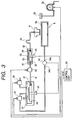
- Fig. 2 shows an embodiment of a printing mechanism of the above device.
- the carriage 3 mounts the recording head 4 for jetting black ink and the recording head 5 for jetting an ink droplet in yellow, cyan and magenta and is reciprocated by a carriage driving motor 11 via a timing belt 10 and ink is supplied to the recording heads 4 and 5 mounted on the carriage from an ink supply system described later.
- the ink supply system is composed of pressurizing chambers 12, 13, 14 and 15 for respectively housing an ink bag with large capacity, for example, 1 liter, in the ink tank housing 9, subtanks 20, 21, 22 and 23 respectively connected to the ink bag via ink transport tubes 16 to 19 and ink supply tubes 24, 25, 26 and 27 connecting the subtanks 20 to 23 and the recording heads 4 and 5.
- electromagnetic stop valves 28, 29, 30 and 31 are respectively connected to the ink transport tubes 16 to 19.
- a capping device 32 for applying negative pressure to prevent blocking caused by the drying of ink in the recording heads 4 an 5 during non-printing, when ink is initially filled in the recording heads 4 and 5 and to solve blocking is provided in a non-printing area so that negative pressure can be applied to the recording heads 4 and 5 via the capping device 32 by suction pump 33.
- a supporting plate 6a on the surface opposite to the recording paper in which thin holes are made is provided on the paper guide 6 so as to apply negative pressure from the suction port 34a of a pump 34 to a recording paper and fix the recording paper on the supporting plate 6a by negative pressure.
- the exhaust port 34b of the pump 34 is connected to the pressurizing chambers 12 to 15 respectively via the electromagnetic stop valves 35, 36, 37 and 38.
- the ink bag as the ink supply means is respectively housed in the pressurizing chambers 12 to 15 and is provided with a connecting port 41 (see FIG. 3) which can be connected to each of the ink transport tubes 16 to 19 on one shorter side 40a of the flexible bag 40 which is made, for example, of an aluminum laminated film.
- the aluminum laminated film may be made by putting aluminum foil as an intermediate layer between two films, for example an outside nylon film and an inside polyethylene film to function as a barrier to gas as shown in Fig. 4.
- the flexible bag 40 may also be made of a light transmissive film obtained by forming a silicon oxide layer by depositing silicon oxide on the surface a polymeric film having a light transmissive property in addition to good flexibility and sealing performance such as polyethylene terephthalate (PET) and a nylon and laminating a polymeric film such as polyethylene having excellent thermal weld characteristics on the surface.
- a light transmissive film obtained by forming a silicon oxide layer by depositing silicon oxide on the surface a polymeric film having a light transmissive property in addition to good flexibility and sealing performance
- PET polyethylene terephthalate
- nylon nylon
- a gusset 42 is provided on the longer side of the ink bag 40 to increase the volume as much as possible and the centers of the shorter side 40b are welded to prevent the bag 40 from being over-expanded uselessly.
- the pressurizing chamber 12 is connected to atmosphere via the exhaust port 34b and the suction port 34a of the pump 34 and the stop valve 39 so that the internal pressure can be arbitrarily adjusted.
- the ink bag 40 is pressurized by controlling the internal pressure of the pressurizing chamber 12, ink in the ink bag 40 can be discharged into the subtank 20 and the residual quantity of ink can be controlled by detecting the degree of the bulge of the ink bag 40 as detected by the ink residual quantity detecting plate 43 and the ink residual quantity detector 44.
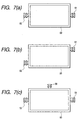
- a bag 50 is made of an aluminum laminated film obtained by putting aluminum foil as an intermediate layer between two films, for example an outside nylon film and an inside polyethylene film to function as a barrier to gas as shown in Fig. 5, or a light transmissive film obtained by forming a silicon oxide layer by depositing silicon oxide on the surface a polymeric film having a light transmissive property in addition to good flexibility and sealing performance such as polyethylene terephthalate (PET) and a nylon.
- PET polyethylene terephthalate
- a bag 50 is formed of an aluminum laminated film by putting aluminum foil as an intermediate layer between two films, for example, an outside nylon film and an inside polyethylene film. The aluminum laminated film functions as a barrier to gas as shown in Fig. 5.
- the bag 50 may also be formed of a light transmissive film by forming a silicon oxide layer by depositing silicon oxide on the surface of a polymeric film such as polyethylene having a light transmissive property in addition to good flexibility and sealing performance such as polyethylene terephthalate (PET) and a nylon.
- the bag 50 is formed in a size in which the shape can flexibly follow the quantity of ink, for example, with a capacity of approximately 100 to 300 cm 3 .
- An inlet 51 connecting to the ink transport tube 16 and an outlet 52 connecting to the ink supply tube 24 are provided on the opposite sides of the bag 50, thereby constituting the subtank 20.
- the bag 50, inlet 51 and the ink supply tube 24 constitute the subtank 20.
- an ink quantity detecting plate 53 is attached to the surface of the ink bag 50 as shown in Fig. 6 and is housed in a protective case 54.
- the variation of pressure in the subtank 20 caused by the inflow of ink from the ink bag 40 and the consumption of ink in the recording head 4 is absorbed by expansion and contraction of the flexible bag 50. Accordingly, ink can be supplied to the recording head under a fixed pressure.
- the quantity of ink in the subtank 20 can be controlled by detecting the displacement of an ink quantity detecting plate 53 which moves as a function of the degree of the bulge of the ink bag 50 by an ink quantity detecting means 55.
- a control unit 60 increases the internal pressure of the pressurizing chamber 12 by closing an electromagnetic stop valve 39 and opening the electromagnetic stop valve 35. This causes ink in the ink bag to be supplied to the subtank 20 through the opening of the electromagnetic stop valve 28.
- the control unit 60 receives a signal from the ink residual quantity detecting means 44 and the ink quantity detecting means 55 and outputs a driving signal to the electromagnetic stop valves 35 and 39.
- the subtank 20 which includes the ink bag 50 which is made of a light transmissive film, as inside bubbles can be detected visually, bubbles can be securely removed.
- the electromagnetic stop valve 28 and the pump 34 for forcing the recording paper against the paper guide 6 are operated after the ink bag 40 is set, the electromagnetic stop valve 39 of the pressurizing chamber 12 housing the ink bag 40 is closed, the electromagnetic stop valve 35 is opened, hereby, pressure in the pressurizing chamber 12 is increased by air from the exhaust port 34b of the pump 34 and the ink bag 40 is contracted.
- the recording head 4 is moved to the capping device 32 in a non-printing area and the suction pump 33 is operated with the recording head 4 sealed with the capping device 32. Negative pressure in the capping device 32 is applied to the ink supply tube 24 and the subtank 20 via the recording head 4, air and ink left in these members are discharged into the capping device 32 and when suction is further continued, the subtank 20 is squeezed by the atmospheric air and is discharged.
- ink in the ink bag 40 flows into the subtank 20 via the ink transport tube 16 and when the ink reaches predetermined quantity, it flows into the recording head 4 via the ink supply tube 24. It is desirable to open the electromagnetic stop valve 35 if necessary with the suction pump 33 operating, and to close the electromagnetic stop valve 39 in order to pressurize the ink bag 50.
- the recording head 4 jets an ink droplet on the surface of recording paper fixed by negative pressure by the paper guide 6 corresponding to print data, thereby to execute printing and the ink bag 50 supplies ink to the recording head 4 via the ink supply tube 24, contracting as ink is consumed.
- the control unit 60 initiates the supply of ink to the subtank 20 by instructing to close the electromagnetic stop valve 39 and to open the electromagnetic valve 35 further to open the electromagnetic stop valve 28, which pressurizes the ink bag 40.
- ink flows into the subtank at some flow rate.
- ink bag 50 disposed in the subtank 20 absorbs the variation of pressure with its own flexibility, ink is supplied under fixed pressure to the recording head 4 without having the effect of the variation of pressure on the recording head 4.
- the control unit 60 instructs the supply of ink to be stopped by instructing to close the electromagnetic stop valve 28 to open the electromagnetic stop valve 39 and to close the electromagnetic stop valve 35. Printing is continued, keeping the quantity of ink in the subtank 20 within a fixed range as described above.
- the suction pump 33 is operated by closing the electromagnetic stop valve 28 and sealing the recording head 4 with the capping device 32.
- the suction pump 33 is operated by closing the electromagnetic stop valve 28 and sealing the recording head 4 with the capping device 32.
- ink in the ink bag 40 flows into the subtank 20, further flows into the recording head 4 via the ink supply tube 24 and printing is enabled.
- the control unit 60 prompts the user to supply ink via a warning means (not shown). While the ink bag 40 is being replaced, printing can be continued by using ink stored in the subtank 20, closing the electromagnetic stop valve 28. Therefore, ink can be supplied without interrupting the printing operation.
- the ink bag 50 comprising the subtank 20 is installed so that the flat surface is horizontal.
- the ink bag may also be installed so that the flat surface is vertical.
- an air vent 56 may be formed in the uppermost part.
- An electromagnetic stop valve is connected to this air vent 56 and may also be open to atmospheric air when ink is filled.
- the subtank 20 is installed on the side of the printer, however, it is clear that if the subtank 20 is installed on the carriage by connecting it via a flexible tube, similar action can be produced.
- the exhaust pressure of the air pump 34 for attracting recording paper is utilized, however, an independent air pump for pressurizing may be also provided.
- a pressing plate of a size in which the whole flat surface of the ink bag 50 is covered is provided.
- the ink bag may also be so constituted that the pressing plate is mechanically displaced.
- the ink residual quantity detecting means such as the ink residual quantity detecting plate 43 is provided to the ink bag 40 to detect the residual quantity of ink.
- a shortage of ink in the ink bag 40 can also be ascertained if the quantity of ink in the subtank 20 does not exceed a reference value, even if the ink bag 40 is pressurized for a predetermined time after the quantity of ink in the subtank 20 has decreased down to the first reference value or less.
- the recording head for jetting an ink droplet corresponding to a printing signal is mounted on the carriage and ink is supplied from the ink reservoir to the recording head via the ink supply tube
- the subtank composed of the flexible ink bag provided with the ink inlet on one side and the ink outlet on the other side is connected on the way of the passage connecting the ink reservoir and the recording head
Landscapes
- Ink Jet (AREA)
Claims (21)
- Appareil d'enregistrement à jets d'encre dans lequel une tête d'enregistrement (4) destinée à projeter une gouttelette d'encre correspondant à un signal d'impression est montée sur un chariot (3) et de l'encre est transmise d'une réserve d'encre (12) à la tête d'enregistrement (4) par un tube d'alimentation en encre, et
une cuve auxiliaire (20) est raccordée à un passage reliant la réserve d'encre (12) à la tête d'enregistrement (4), caractérisé en ce que la cuve auxiliaire (20) comporte un sac souple d'encre (50) ayant une entrée d'encre (51) et une sortie d'encre (52). - Appareil d'enregistrement à jets d'encre selon la revendication 1, dans lequel une vanne d'arrêt (28) est placée dans un passage (16) qui relie la cuve auxiliaire (20) à la réserve d'encre (40).
- Appareil d'enregistrement à jets d'encre selon la revendication 1 ou 2, dans lequel la sortie d'encre (52) de la cuve auxiliaire (20) est disposée afin qu'elle soit plus basse qu'un premier niveau prédéterminé de référence.
- Appareil d'enregistrement à jets d'encre selon l'une quelconque des revendications précédentes, dans lequel le sac d'encre (50) comporte un film polymère ayant une couche formant un barrage pour le gaz.
- Appareil d'enregistrement à jets d'encre selon la revendication 4, dans lequel la couche formant un barrage pour le gaz est formée d'un métal ou d'oxyde de silicium.
- Appareil d'enregistrement à jets d'encre selon l'une quelconque des revendications précédentes, dans lequel la cuve auxiliaire (20) comporte un dispositif (53, 55) de détection de la quantité résiduelle d'encre dans celui-ci.
- Appareil d'enregistrement à jets d'encre selon l'une quelconque des revendications précédentes, dans lequel la cuve auxiliaire (20) est disposée sur le chariot (3).
- Appareil d'enregistrement à jets d'encre selon l'une quelconque des revendications précédentes, dans lequel la cuve auxiliaire (20) est disposée afin que sa surface plate soit horizontale.
- Appareil d'enregistrement à jets d'encre selon l'une quelconque des revendications 1 à 7, dans lequel la cuve auxiliaire (20) est disposée afin que sa surface plate soit verticale.
- Appareil d'enregistrement à jets d'encre selon l'une quelconque des revendications précédentes, dans lequel la réserve d'encre (12) comporte un sac souple (40) et est mise sous pression par un dispositif de mise sous pression.
- Appareil d'enregistrement à jets d'encre selon la revendication 10, dans lequel le sac souple (40) est mis sous pression par un dispositif (34) de transmission d'air.
- Appareil d'enregistrement à jets d'encre selon la revendication 11, comprenant en outre un guide de papier (6) destiné à supporter un support d'enregistrement, et dans lequel une dépression est appliquée au guide de papier (6) par une pompe aspirante (34), et le dispositif d'alimentation en air (34) est la pompe aspirante (34).
- Appareil d'enregistrement à jets d'encre selon la revendication 10, dans lequel le dispositif de mise sous pression comporte une plaque d'application d'une pression au sac souple (40) par déplacement mécanique.
- Appareil d'enregistrement à jets d'encre selon l'une quelconque des revendications précédentes, dans lequel la cuve auxiliaire (20) a un dispositif (53, 55) de détection de la quantité résiduelle d'encre, et la quantité résiduelle d'encre dans la cuve auxiliaire (20) est réglée d'après un signal provenant du dispositif (53, 55) de détection de la quantité résiduelle d'encre.
- Procédé de remplissage d'encre d'un appareil d'enregistrement à jets d'encre dans lequel une tête d'enregistrement destinée à projeter une gouttelette d'encre qui correspond à un signal d'impression est montée sur un chariot, une cuve auxiliaire contenant un sac souple d'encre, munie d'une entrée d'encre et d'une sortie d'encre, étant connectée à un passage raccordant une réserve d'encre à la tête d'enregistrement et une vanne d'arrêt étant raccordée entre la cuve auxiliaire et la réserve d'encre, le procédé comprenant les étapes suivantes :la fermeture de la vanne d'arrêt, l'application d'une dépression à la tête d'enregistrement, et l'application d'une pression à la cuve auxiliaire à la pression atmosphérique, etl'ouverture de la vanne d'arrêt et le remplissage de la cuve auxiliaire par de l'encre.
- Procédé d'alimentation en encre d'un appareil d'enregistrement à jets d'encre dans lequel une tête d'enregistrement destinée à projeter une gouttelette d'encre correspondant à un signal d'impression est montée sur un chariot, une cuve auxiliaire comprenant un sac souple d'encre est munie d'une entrée d'encre et d'une sortie d'encre et est raccordée à un passage reliant une réserve d'encre à la tête d'enregistrement, et une vanne d'arrêt est raccordée entre la cuve auxiliaire et la réserve d'encre, le procédé comprenant les étapes suivantes :la fermeture de la vanne d'arrêt et le remplacement de la réserve d'encre lorsque la quantité d'encre dans la réserve d'encre diminue au-dessous d'un niveau prédéterminé, etla poursuite de l'alimentation en encre provenant de la cuve auxiliaire et destinée à la tête d'enregistrement pendant que la réserve d'encre est en cours de remplacement.
- Appareil d'enregistrement à jets d'encre comprenant :une tête d'enregistrement à jets d'encre (4) destinée à projeter des gouttelettes d'encre sur un support d'enregistrement,une réserve d'encre (12) destinée à transmettre de l'encre à la tête d'enregistrement à jets d'encre (4), etune cuve auxiliaire (20) raccordée à la réserve (12) et à la tête d'enregistrement à jets d'encre (4) et destinée à transmettre de l'encre à la tête d'enregistrement à jets d'encre (4), caractérisé en ce que la cuve auxiliaire (20) comporte un sac souple d'encre (50) qui transmet de l'encre à la tête d'enregistrement à jets d'encre (4) à une pression fixe.
- Appareil d'enregistrement à jets d'encre selon la revendication 17, comprenant en outre un détecteur d'encre (55) qui détecte la quantité d'encre dans la cuve auxiliaire (20).
- Appareil d'enregistrement à jets d'encre selon la revendication 18, dans lequel le détecteur (55) comporte une plaque de détection (53) qui mesure le déplacement du sac d'encre (50).
- Appareil d'enregistrement à jets d'encre selon la revendication 18 ou 19, comprenant en outre une unité de commande (60) qui provoque la transmission d'encre de la réserve d'encre (12) à la cuve auxiliaire (20) lorsque le niveau de l'encre dans la cuve auxiliaire (20) diminue au-dessous d'une première valeur prédéterminée, et qui arrête la transmission d'encre de la réserve d'encre (12) à la cuve auxiliaire (20) lorsque le niveau de l'encre dans la cuve auxiliaire (20) dépasse une seconde valeur prédéterminée.
- Appareil d'enregistrement à jets d'encre selon l'une quelconque des revendications 17 à 20, comprenant en outre une vanne (28) qui ferme une connexion formée entre la réserve (12) et la tête d'enregistrement à jets d'encre (4) lorsque l'encre de la réserve d'encre (12) est en cours de remplacement.
Applications Claiming Priority (2)
| Application Number | Priority Date | Filing Date | Title |
|---|---|---|---|
| JP10012101A JPH11192720A (ja) | 1998-01-05 | 1998-01-05 | インクジェット式記録装置、インク充填方法、及びインク補給方法 |
| JP1210198 | 1998-01-05 |
Publications (3)
| Publication Number | Publication Date |
|---|---|
| EP0927638A2 EP0927638A2 (fr) | 1999-07-07 |
| EP0927638A3 EP0927638A3 (fr) | 1999-08-18 |
| EP0927638B1 true EP0927638B1 (fr) | 2001-07-18 |
Family
ID=11796187
Family Applications (1)
| Application Number | Title | Priority Date | Filing Date |
|---|---|---|---|
| EP98124704A Expired - Lifetime EP0927638B1 (fr) | 1998-01-05 | 1998-12-24 | Dispositif d'enregistrement à jet d'encre avec container intermédiaire entre réservoir d'encre et tête d'enregistrement |
Country Status (4)
| Country | Link |
|---|---|
| US (1) | US6267474B1 (fr) |
| EP (1) | EP0927638B1 (fr) |
| JP (1) | JPH11192720A (fr) |
| DE (1) | DE69801147T2 (fr) |
Families Citing this family (63)
| Publication number | Priority date | Publication date | Assignee | Title |
|---|---|---|---|---|
| US6547377B2 (en) * | 1998-03-09 | 2003-04-15 | Hewlett-Packard Company | Printhead air management using unsaturated ink |
| EP1142713B9 (fr) | 1999-11-05 | 2010-07-21 | Seiko Epson Corporation | Dispositif d'impression de type jet d'encre, procede d'alimentation en encre de reservoir secondaire et procede d'evaluation de quantite d'encre fournie a ce reservoir par le meme dispositif |
| EP1120258B1 (fr) | 2000-01-21 | 2006-05-17 | Seiko Epson Corporation | Cassette d'encre et appareil d'enregistrement par jet d'encre l'utilisant |
| DE60135044D1 (de) | 2000-01-21 | 2008-09-04 | Seiko Epson Corp | Tintenstrahlaufzeichnungsgerät |
| KR100617280B1 (ko) * | 2000-01-21 | 2006-08-30 | 세이코 엡슨 가부시키가이샤 | 잉크 카트리지 및 잉크젯식 기록 장치 |
| JP4510981B2 (ja) * | 2000-02-29 | 2010-07-28 | セイコーエプソン株式会社 | インクジェット式記録装置 |
| EP1188568B1 (fr) * | 2000-03-27 | 2006-05-03 | Seiko Epson Corporation | Enregistreur a jet d'encre |
| AUPQ757900A0 (en) * | 2000-05-18 | 2000-06-08 | Champion Imaging Systems Pty Ltd | Print station |
| EP1164022B1 (fr) | 2000-06-16 | 2008-07-30 | Canon Kabushiki Kaisha | Appareil d'enregistrement à jet d'encre utilisant un élément semi-conducteur solide |
| US6626516B2 (en) * | 2000-09-20 | 2003-09-30 | Canon Kabushiki Kaisha | Ink jet printing apparatus, method of supplying ink and method of recovering ink jet print head |
| ATE402017T1 (de) | 2001-02-09 | 2008-08-15 | Seiko Epson Corp | Tintenstrahlaufzeichnungsvorrichtung, steuerungs- und tintennachfüllsverfahren in der vorrichtung ausgeführt, tintenversorgungssystem in der vorrichtung, und verwaltungsverfahren der von dem system versorgt tintenmenge |
| JP4522620B2 (ja) * | 2001-02-09 | 2010-08-11 | セイコーエプソン株式会社 | インク供給システム及びそのシステムにおけるインク供給量の管理方法 |
| CN101177069B (zh) * | 2001-02-09 | 2012-06-13 | 精工爱普生株式会社 | 供墨系统和管理系统供墨量的方法 |
| US20020118260A1 (en) | 2001-02-23 | 2002-08-29 | Waggoner Karen Wytmans | Inkjet printing system |
| JP4517519B2 (ja) * | 2001-02-26 | 2010-08-04 | セイコーエプソン株式会社 | インクパックの支持構造およびこれを備えたインク供給装置 |
| JP3668439B2 (ja) * | 2001-06-14 | 2005-07-06 | ソニーケミカル株式会社 | 接着フィルム |
| JP2002370375A (ja) | 2001-06-18 | 2002-12-24 | Canon Inc | インクジェットプリント装置、インクタンクおよびインク供給方法 |
| WO2003053701A1 (fr) * | 2001-12-21 | 2003-07-03 | Olympus Corporation | Imprimante a jet d'encre |
| KR100387551B1 (en) * | 2002-03-12 | 2003-06-18 | Hanlim | Ink feeding device for large ink jet printer |
| US6877846B2 (en) * | 2002-05-03 | 2005-04-12 | Eastman Kodak Company | Replaceable ink jet supply with anti-siphon back pressure control |
| JP2004074462A (ja) * | 2002-08-12 | 2004-03-11 | Sii Printek Inc | エアーダンパー及びインクジェットヘッド並びにインクジェット式記録装置 |
| JP2004090432A (ja) * | 2002-08-30 | 2004-03-25 | Seiko Epson Corp | 液体噴射装置、液体噴射装置の液体排出用タンク及び液体噴射装置の液体排出方法 |
| JP4193719B2 (ja) | 2003-03-05 | 2008-12-10 | セイコーエプソン株式会社 | 液体収容体、液体噴射装置及び液体収容ケース |
| EP1603752B1 (fr) * | 2003-03-18 | 2010-11-03 | Ricoh Company, Ltd. | Sachet a encre et cartouche a encre comprenant le sachet a encre |
| NL1023215C2 (nl) | 2003-04-17 | 2004-10-19 | Stork Digital Imaging Bv | Drukinrichting, flexibele voorraadhouder en werkhouder, alsmede toevoersysteem. |
| US7438400B2 (en) | 2003-07-16 | 2008-10-21 | Seiko Epson Corporation | Liquid container, liquid ejecting device, and method of checking arrangement of liquid storing packs |
| JP2005047058A (ja) * | 2003-07-30 | 2005-02-24 | Canon Inc | インクジェット記録装置 |
| US7384133B2 (en) * | 2003-08-08 | 2008-06-10 | Seiko Epson Corporation | Liquid container capable of maintaining airtightness |
| US6942324B2 (en) * | 2003-10-14 | 2005-09-13 | Kevin R. Campion | Fluid delivery system for an ink jet print head |
| US20050157112A1 (en) | 2004-01-21 | 2005-07-21 | Silverbrook Research Pty Ltd | Inkjet printer cradle with shaped recess for receiving a printer cartridge |
| US7448734B2 (en) | 2004-01-21 | 2008-11-11 | Silverbrook Research Pty Ltd | Inkjet printer cartridge with pagewidth printhead |
| US7258432B2 (en) * | 2004-01-21 | 2007-08-21 | Silverbrook Research Pty Ltd | Inkjet printer cartridge with controlled refill |
| US20050206693A1 (en) * | 2004-03-22 | 2005-09-22 | Stephen Chen | High capacity ink supply apparatus |
| US7377626B2 (en) * | 2004-07-09 | 2008-05-27 | Nukote International, Inc. | External ink supply bag and method of filling the same |
| US20060007278A1 (en) * | 2004-07-09 | 2006-01-12 | Nu-Kote International, Inc., A Corporation Of Delaware | Ink delivery system for the continuous refill of ink jet cartridges |
| JP2006035484A (ja) * | 2004-07-23 | 2006-02-09 | Seiko Epson Corp | 液体容器および液体残量検出方法 |
| JP2006137181A (ja) * | 2004-10-15 | 2006-06-01 | Seiko Epson Corp | 充填方法、および、液体吐出装置 |
| US20060125887A1 (en) * | 2004-12-15 | 2006-06-15 | Hwang Peter G | Fluid reservoir and ink pen assembly |
| JP4788142B2 (ja) * | 2005-01-14 | 2011-10-05 | セイコーエプソン株式会社 | 液体収容体及び液体噴射装置 |
| JP4725157B2 (ja) * | 2005-03-28 | 2011-07-13 | セイコーエプソン株式会社 | 液体噴射装置 |
| WO2006112208A1 (fr) * | 2005-03-30 | 2006-10-26 | Seiko Epson Corporation | Recipient de liquide |
| WO2006121109A1 (fr) * | 2005-05-13 | 2006-11-16 | Brother Kogyo Kabushiki Kaisha | Appareil d’enregistrement à jet d’encre |
| US7771028B2 (en) * | 2005-10-11 | 2010-08-10 | Silverbrook Research Pty Ltd | Ink supply system comprising pressure device and in-line valve |
| US7577384B2 (en) * | 2005-12-23 | 2009-08-18 | Xerox Corporation | Collapsible packaging system |
| US8967044B2 (en) * | 2006-02-21 | 2015-03-03 | R.R. Donnelley & Sons, Inc. | Apparatus for applying gating agents to a substrate and image generation kit |
| JP2007283557A (ja) * | 2006-04-13 | 2007-11-01 | Seiko Epson Corp | 液体収容体 |
| JP2008037097A (ja) | 2006-07-10 | 2008-02-21 | Seiko Epson Corp | 液体供給システム及び液体消費装置 |
| JP2008143073A (ja) | 2006-12-12 | 2008-06-26 | Ricoh Co Ltd | 画像形成装置及び制御方法 |
| JP5241515B2 (ja) * | 2007-01-19 | 2013-07-17 | シャープ株式会社 | インク吐出装置 |
| US8322835B2 (en) * | 2007-02-19 | 2012-12-04 | Seiko Epson Corporation | Sealing structure of fluid container, and method of manufacturing and reusing fluid container |
| JP2008230214A (ja) * | 2007-02-19 | 2008-10-02 | Seiko Epson Corp | 流体導出部のシール構造体及びシール方法並びに流体収容容器、再充填流体収容容器及びその再充填方法 |
| US20090027463A1 (en) * | 2007-07-24 | 2009-01-29 | Berg Richard H | Wide format ink cartridge |
| JP2009166358A (ja) * | 2008-01-16 | 2009-07-30 | Seiko Epson Corp | 液体供給方法、液体供給システム及び液体噴射装置 |
| EP2274174B1 (fr) * | 2008-05-14 | 2013-08-07 | Hewlett-Packard Development Company, L.P. | Systèmes d alimentation en encre pour imprimante |
| JP5561925B2 (ja) * | 2008-10-14 | 2014-07-30 | 株式会社ミマキエンジニアリング | バルクインク供給装置 |
| KR101215197B1 (ko) * | 2012-03-21 | 2012-12-24 | 김영숙 | 잉크공급장치 및 잉크팩 수납케이스 |
| JP5692265B2 (ja) * | 2013-03-07 | 2015-04-01 | セイコーエプソン株式会社 | 液体噴射装置、液体供給装置及び液体収容体 |
| JP6384233B2 (ja) * | 2014-09-24 | 2018-09-05 | ブラザー工業株式会社 | 印刷装置 |
| US9573380B2 (en) * | 2015-03-23 | 2017-02-21 | Seiko Epson Corporation | Liquid discharging apparatus |
| JP6657583B2 (ja) * | 2015-03-31 | 2020-03-04 | セイコーエプソン株式会社 | 液体供給装置および液体消費装置 |
| KR102346945B1 (ko) * | 2015-08-11 | 2022-01-05 | 배준호 | 무한 리필 잉크공급장치 |
| JP7292947B2 (ja) * | 2019-04-24 | 2023-06-19 | キヤノン株式会社 | インクジェット記録装置及びインクジェット記録装置の制御方法 |
| JP7463823B2 (ja) * | 2019-04-26 | 2024-04-09 | ブラザー工業株式会社 | 画像記録装置 |
Family Cites Families (16)
| Publication number | Priority date | Publication date | Assignee | Title |
|---|---|---|---|---|
| JPS54151033A (en) * | 1978-05-18 | 1979-11-27 | Fujitsu Ltd | Ink feed device in ink jet recorder |
| US4207579A (en) * | 1979-01-08 | 1980-06-10 | The Mead Corporation | Reciprocating paper handling apparatus for use in an ink jet copier |
| JPS5616886U (fr) * | 1979-07-17 | 1981-02-14 | ||
| DE3137970A1 (de) * | 1981-09-24 | 1983-03-31 | Olympia Werke Ag, 2940 Wilhelmshaven | Tintenschreibwerk fuer bueromaschinen mit auf einem bewegbaren wagen angeordneten tintenschreibkopf und tintenzwischenbehaelter |
| US4432005A (en) * | 1982-05-10 | 1984-02-14 | Advanced Color Technology, Inc. | Ink control system for ink jet printer |
| DE3244935A1 (de) * | 1982-12-04 | 1984-06-07 | Olympia Werke Ag, 2940 Wilhelmshaven | Tintenschreibwerk fuer bueromaschinen |
| US4604633A (en) * | 1982-12-08 | 1986-08-05 | Konishiroku Photo Industry Co., Ltd | Ink-jet recording apparatus |
| JPH0671791B2 (ja) * | 1983-07-20 | 1994-09-14 | キヤノン株式会社 | インクジエツトプリンタのインク残量検知方法 |
| JPS60179258A (ja) * | 1984-02-28 | 1985-09-13 | Fujitsu Ltd | インクジエツトプリンタのインク供給機構 |
| JPS62290544A (ja) * | 1986-06-10 | 1987-12-17 | Nec Corp | インクジエツトプリンタのインク供給機構 |
| US4965596A (en) * | 1988-02-09 | 1990-10-23 | Canon Kabushiki Kaisha | Ink jet recording apparatus with waste ink distribution paths to plural cartridges |
| JP2822586B2 (ja) | 1990-04-19 | 1998-11-11 | 富士ゼロックス株式会社 | インクジェットプリンター |
| JP3252392B2 (ja) | 1994-05-17 | 2002-02-04 | セイコーエプソン株式会社 | インクジェット式記録装置、及び記録ヘッドのクリーニング方法 |
| US5831655A (en) * | 1995-03-23 | 1998-11-03 | Seiko Epson Corporation | Ink jet recording apparatus |
| US5886718A (en) * | 1995-09-05 | 1999-03-23 | Hewlett-Packard Company | Ink-jet off axis ink delivery system |
| JP3414605B2 (ja) | 1995-12-25 | 2003-06-09 | セイコーエプソン株式会社 | インクジェット記録装置、及びメンテナンス方法 |
-
1998
- 1998-01-05 JP JP10012101A patent/JPH11192720A/ja active Pending
- 1998-12-24 DE DE69801147T patent/DE69801147T2/de not_active Expired - Lifetime
- 1998-12-24 EP EP98124704A patent/EP0927638B1/fr not_active Expired - Lifetime
-
1999
- 1999-01-05 US US09/225,359 patent/US6267474B1/en not_active Expired - Lifetime
Also Published As
| Publication number | Publication date |
|---|---|
| US6267474B1 (en) | 2001-07-31 |
| EP0927638A2 (fr) | 1999-07-07 |
| DE69801147D1 (de) | 2001-08-23 |
| EP0927638A3 (fr) | 1999-08-18 |
| JPH11192720A (ja) | 1999-07-21 |
| DE69801147T2 (de) | 2002-03-21 |
Similar Documents
| Publication | Publication Date | Title |
|---|---|---|
| EP0927638B1 (fr) | Dispositif d'enregistrement à jet d'encre avec container intermédiaire entre réservoir d'encre et tête d'enregistrement | |
| EP0894631B1 (fr) | Appareil d'enregistrement à jet d'encre | |
| US7077513B2 (en) | Ink jet recording apparatus, control and ink replenishing method executed in the same, ink supply system incorporated in the same, and method of managing ink amount supplied by the system | |
| JP3419220B2 (ja) | インクジェット式記録装置 | |
| JP3658373B2 (ja) | 液体貯蔵容器、インクジェットカートリッジ、および、インクジェット記録装置 | |
| JP2001301192A (ja) | インクジェット記録装置 | |
| JP2002248787A (ja) | 液体噴射装置 | |
| WO2006070518A1 (fr) | Pompe a tube, dispositif d'enregistrement a jet d'encre et procede d'alimentation d'encre | |
| JP3508815B2 (ja) | インクジェット式記録装置 | |
| JPH1148493A (ja) | インクジェット式記録装置 | |
| JP2003159811A (ja) | インクジェット式記録装置 | |
| JP3363760B2 (ja) | インク供給装置およびプリント装置 | |
| JPH11320901A (ja) | インクジェット記録装置 | |
| JP4089231B2 (ja) | インク充填方法及びインクジェット式記録装置 | |
| JP3512057B2 (ja) | インクジェット式記録装置 | |
| JP2009023251A (ja) | インクジェット記録装置 | |
| JP2000301732A (ja) | インクジェット記録装置 | |
| JP4009821B2 (ja) | インク充填方法及びインクジェット式記録装置 | |
| JP4687111B2 (ja) | インクジェット記録装置 | |
| JP4852203B2 (ja) | インク供給装置の空気排出方法 | |
| JP4602116B2 (ja) | インクジェット式記録装置、チューブポンプおよび液体送液方法 | |
| JP2001001536A (ja) | インクジェット式記録装置 | |
| US11285730B2 (en) | Liquid ejection apparatus and liquid filling method in liquid ejection apparatus | |
| US20040189753A1 (en) | Inkjet printer | |
| JP2002264358A (ja) | インクジェット画像形成装置 |
Legal Events
| Date | Code | Title | Description |
|---|---|---|---|
| PUAI | Public reference made under article 153(3) epc to a published international application that has entered the european phase |
Free format text: ORIGINAL CODE: 0009012 |
|
| PUAL | Search report despatched |
Free format text: ORIGINAL CODE: 0009013 |
|
| AK | Designated contracting states |
Kind code of ref document: A2 Designated state(s): DE FR GB |
|
| AX | Request for extension of the european patent |
Free format text: AL;LT;LV;MK;RO;SI |
|
| AK | Designated contracting states |
Kind code of ref document: A3 Designated state(s): AT BE CH CY DE DK ES FI FR GB GR IE IT LI LU MC NL PT SE |
|
| AX | Request for extension of the european patent |
Free format text: AL;LT;LV;MK;RO;SI |
|
| 17P | Request for examination filed |
Effective date: 20000215 |
|
| AKX | Designation fees paid |
Free format text: DE FR GB |
|
| 17Q | First examination report despatched |
Effective date: 20000407 |
|
| GRAG | Despatch of communication of intention to grant |
Free format text: ORIGINAL CODE: EPIDOS AGRA |
|
| GRAG | Despatch of communication of intention to grant |
Free format text: ORIGINAL CODE: EPIDOS AGRA |
|
| GRAH | Despatch of communication of intention to grant a patent |
Free format text: ORIGINAL CODE: EPIDOS IGRA |
|
| GRAH | Despatch of communication of intention to grant a patent |
Free format text: ORIGINAL CODE: EPIDOS IGRA |
|
| GRAA | (expected) grant |
Free format text: ORIGINAL CODE: 0009210 |
|
| AK | Designated contracting states |
Kind code of ref document: B1 Designated state(s): DE FR GB |
|
| REF | Corresponds to: |
Ref document number: 69801147 Country of ref document: DE Date of ref document: 20010823 |
|
| ET | Fr: translation filed | ||
| REG | Reference to a national code |
Ref country code: GB Ref legal event code: IF02 |
|
| PLBE | No opposition filed within time limit |
Free format text: ORIGINAL CODE: 0009261 |
|
| STAA | Information on the status of an ep patent application or granted ep patent |
Free format text: STATUS: NO OPPOSITION FILED WITHIN TIME LIMIT |
|
| 26N | No opposition filed | ||
| REG | Reference to a national code |
Ref country code: FR Ref legal event code: PLFP Year of fee payment: 18 |
|
| REG | Reference to a national code |
Ref country code: FR Ref legal event code: PLFP Year of fee payment: 19 |
|
| REG | Reference to a national code |
Ref country code: FR Ref legal event code: PLFP Year of fee payment: 20 |
|
| PGFP | Annual fee paid to national office [announced via postgrant information from national office to epo] |
Ref country code: FR Payment date: 20171113 Year of fee payment: 20 |
|
| PGFP | Annual fee paid to national office [announced via postgrant information from national office to epo] |
Ref country code: GB Payment date: 20171220 Year of fee payment: 20 |
|
| PGFP | Annual fee paid to national office [announced via postgrant information from national office to epo] |
Ref country code: DE Payment date: 20171220 Year of fee payment: 20 |
|
| REG | Reference to a national code |
Ref country code: DE Ref legal event code: R071 Ref document number: 69801147 Country of ref document: DE |
|
| REG | Reference to a national code |
Ref country code: GB Ref legal event code: PE20 Expiry date: 20181223 |
|
| PG25 | Lapsed in a contracting state [announced via postgrant information from national office to epo] |
Ref country code: GB Free format text: LAPSE BECAUSE OF EXPIRATION OF PROTECTION Effective date: 20181223 |