EP0928007A1 - Procédé de conduite d'un réacteur dans des conditions de fonctionnement instable et système adapté à sa mise en oeuvre - Google Patents
Procédé de conduite d'un réacteur dans des conditions de fonctionnement instable et système adapté à sa mise en oeuvre Download PDFInfo
- Publication number
- EP0928007A1 EP0928007A1 EP98123358A EP98123358A EP0928007A1 EP 0928007 A1 EP0928007 A1 EP 0928007A1 EP 98123358 A EP98123358 A EP 98123358A EP 98123358 A EP98123358 A EP 98123358A EP 0928007 A1 EP0928007 A1 EP 0928007A1
- Authority
- EP
- European Patent Office
- Prior art keywords
- reactor
- area
- monitoring
- signal
- alarm
- Prior art date
- Legal status (The legal status is an assumption and is not a legal conclusion. Google has not performed a legal analysis and makes no representation as to the accuracy of the status listed.)
- Granted
Links
- 238000000034 method Methods 0.000 title claims abstract description 41
- 238000012544 monitoring process Methods 0.000 claims abstract description 97
- 230000010355 oscillation Effects 0.000 claims abstract description 90
- 230000006641 stabilisation Effects 0.000 claims abstract description 53
- 238000009835 boiling Methods 0.000 claims abstract description 8
- XLYOFNOQVPJJNP-UHFFFAOYSA-N water Substances O XLYOFNOQVPJJNP-UHFFFAOYSA-N 0.000 claims abstract description 8
- 238000011105 stabilization Methods 0.000 claims description 51
- 238000011156 evaluation Methods 0.000 claims description 15
- 239000006096 absorbing agent Substances 0.000 claims description 9
- 238000005259 measurement Methods 0.000 claims description 7
- 230000001419 dependent effect Effects 0.000 claims description 6
- 238000012806 monitoring device Methods 0.000 claims description 6
- 230000009467 reduction Effects 0.000 claims description 6
- 230000000977 initiatory effect Effects 0.000 claims description 4
- 230000002829 reductive effect Effects 0.000 claims description 2
- 238000005070 sampling Methods 0.000 claims description 2
- 230000000368 destabilizing effect Effects 0.000 claims 4
- 240000007124 Brassica oleracea Species 0.000 claims 1
- 235000003899 Brassica oleracea var acephala Nutrition 0.000 claims 1
- 235000012905 Brassica oleracea var viridis Nutrition 0.000 claims 1
- 239000000446 fuel Substances 0.000 description 18
- 239000000523 sample Substances 0.000 description 10
- 238000012545 processing Methods 0.000 description 8
- 230000000712 assembly Effects 0.000 description 7
- 238000000429 assembly Methods 0.000 description 7
- 238000013016 damping Methods 0.000 description 7
- 230000036961 partial effect Effects 0.000 description 7
- 238000012790 confirmation Methods 0.000 description 4
- 230000004907 flux Effects 0.000 description 4
- 239000007788 liquid Substances 0.000 description 4
- 230000010349 pulsation Effects 0.000 description 4
- 230000001052 transient effect Effects 0.000 description 4
- 239000002826 coolant Substances 0.000 description 3
- 238000012821 model calculation Methods 0.000 description 3
- 230000003287 optical effect Effects 0.000 description 3
- 230000008901 benefit Effects 0.000 description 2
- 230000000903 blocking effect Effects 0.000 description 2
- 238000004364 calculation method Methods 0.000 description 2
- 238000001816 cooling Methods 0.000 description 2
- 239000000498 cooling water Substances 0.000 description 2
- 230000003247 decreasing effect Effects 0.000 description 2
- 238000001514 detection method Methods 0.000 description 2
- 238000005516 engineering process Methods 0.000 description 2
- 239000000463 material Substances 0.000 description 2
- 239000000203 mixture Substances 0.000 description 2
- 230000008569 process Effects 0.000 description 2
- 230000000630 rising effect Effects 0.000 description 2
- 230000007704 transition Effects 0.000 description 2
- 230000001960 triggered effect Effects 0.000 description 2
- 238000011144 upstream manufacturing Methods 0.000 description 2
- 230000006399 behavior Effects 0.000 description 1
- 230000009286 beneficial effect Effects 0.000 description 1
- 230000033228 biological regulation Effects 0.000 description 1
- 230000005540 biological transmission Effects 0.000 description 1
- 238000011088 calibration curve Methods 0.000 description 1
- 230000008859 change Effects 0.000 description 1
- 238000006243 chemical reaction Methods 0.000 description 1
- 238000005253 cladding Methods 0.000 description 1
- 238000005352 clarification Methods 0.000 description 1
- 230000002950 deficient Effects 0.000 description 1
- 238000010586 diagram Methods 0.000 description 1
- 230000000694 effects Effects 0.000 description 1
- 230000005284 excitation Effects 0.000 description 1
- 230000004992 fission Effects 0.000 description 1
- 230000006870 function Effects 0.000 description 1
- 239000003365 glass fiber Substances 0.000 description 1
- 230000036039 immunity Effects 0.000 description 1
- 230000010354 integration Effects 0.000 description 1
- 230000002427 irreversible effect Effects 0.000 description 1
- 230000007257 malfunction Effects 0.000 description 1
- 230000000737 periodic effect Effects 0.000 description 1
- 230000010363 phase shift Effects 0.000 description 1
- 230000000704 physical effect Effects 0.000 description 1
- 230000004936 stimulating effect Effects 0.000 description 1
- 239000000126 substance Substances 0.000 description 1
- 230000002123 temporal effect Effects 0.000 description 1
- 238000012360 testing method Methods 0.000 description 1
- 230000003313 weakening effect Effects 0.000 description 1
Images



Classifications
-
- G—PHYSICS
- G21—NUCLEAR PHYSICS; NUCLEAR ENGINEERING
- G21D—NUCLEAR POWER PLANT
- G21D3/00—Control of nuclear power plant
- G21D3/08—Regulation of any parameters in the plant
-
- G—PHYSICS
- G21—NUCLEAR PHYSICS; NUCLEAR ENGINEERING
- G21C—NUCLEAR REACTORS
- G21C7/00—Control of nuclear reaction
-
- Y—GENERAL TAGGING OF NEW TECHNOLOGICAL DEVELOPMENTS; GENERAL TAGGING OF CROSS-SECTIONAL TECHNOLOGIES SPANNING OVER SEVERAL SECTIONS OF THE IPC; TECHNICAL SUBJECTS COVERED BY FORMER USPC CROSS-REFERENCE ART COLLECTIONS [XRACs] AND DIGESTS
- Y02—TECHNOLOGIES OR APPLICATIONS FOR MITIGATION OR ADAPTATION AGAINST CLIMATE CHANGE
- Y02E—REDUCTION OF GREENHOUSE GAS [GHG] EMISSIONS, RELATED TO ENERGY GENERATION, TRANSMISSION OR DISTRIBUTION
- Y02E30/00—Energy generation of nuclear origin
-
- Y—GENERAL TAGGING OF NEW TECHNOLOGICAL DEVELOPMENTS; GENERAL TAGGING OF CROSS-SECTIONAL TECHNOLOGIES SPANNING OVER SEVERAL SECTIONS OF THE IPC; TECHNICAL SUBJECTS COVERED BY FORMER USPC CROSS-REFERENCE ART COLLECTIONS [XRACs] AND DIGESTS
- Y02—TECHNOLOGIES OR APPLICATIONS FOR MITIGATION OR ADAPTATION AGAINST CLIMATE CHANGE
- Y02E—REDUCTION OF GREENHOUSE GAS [GHG] EMISSIONS, RELATED TO ENERGY GENERATION, TRANSMISSION OR DISTRIBUTION
- Y02E30/00—Energy generation of nuclear origin
- Y02E30/30—Nuclear fission reactors
Definitions
- the invention relates to a method for operating a boiling water reactor, by local oscillation of a physical Size (especially the performance or the associated Neutron flux) is in an unstable state.
- the invention also relates to a device for carrying it out this method as well as a method and a device to monitor this unstable reactor condition.
- the nuclear fission that determines the performance of a nuclear reactor is controlled by absorber elements for weakening of the neutron flux are retracted into the reactor core.
- absorber elements for weakening of the neutron flux are retracted into the reactor core.
- sensors for the Flow of thermal neutrons distributed to the current state to capture are measuring lances with sensors for the Flow of thermal neutrons distributed to the current state to capture.
- the throughput of cooling water must be the same serves as a moderator, be adapted to the respective state.
- This cooling water enters the reactor core as a liquid from below one, flows through the fuel assemblies in which it partially evaporates, and occurs as a vapor / liquid mixture out of the core, reducing the fuel / moderator ratio changes in the different parts of the fuel assemblies.
- the flow conditions also change, especially the place where the 1-phase flow with the the liquid coolant enters the fuel assemblies in the 2-phase flow of the liquid / vapor mixture passes.
- This includes high performance and low coolant throughput unstable conditions have been observed in which this Phase boundary starts to oscillate, causing a pulsation the moderator density and the performance that results affects the cooling capacity and the movement of the phase boundary. Periodic Temperature fluctuations with significant peaks occur.
- the maximum permissible power of the fuel elements is mainly limited by the temperature resistance of the materials used in the fuel elements. If an upper temperature limit is exceeded, these materials lose their mechanical, chemical and physical properties and can undergo irreversible changes that can force the fuel elements to be replaced. It must therefore be ensured that this thermal-hydraulic power limit (and thus a thermal-hydraulic limit value A th of the neutron flux) is not exceeded in the reactor.
- the operating permits for the reactors therefore provide that in the event of a limit value being exceeded, the reactor is shut down quickly (so-called "SCRAM"), in which, after an emergency program, all control rods are quickly retracted and the corresponding cooling capacity is set.
- the flow as a measured variable for the through local oscillation of a physical quantity to use unstable condition, taking this flow measurement the measuring lances mentioned ("local power range monitor strings", LPRM strings) can be used.
- Each such lance contains usually four sensors, the signals for the anyway Performance control observed, processed and documented become.
- Each of these four sensors is used in each measuring probe, where two sensors a first monitoring system, the two remaining sensors a redundant second Monitoring system are assigned.
- Any surveillance system contains two monitoring channels, each sensor signal assigned a measuring probe to another monitoring channel is.
- the two monitoring channels of a system lie different divisions of the reactor into individual ones Areas ("monitoring cells") underlie each cell of four measuring lances to form a corresponding range signal is limited.
- a sensor signal belongs (inside the core or at the edge of the core) to two, three or four cells in each monitoring channel. This multiple use of the sensor signals is intended achieved that practically the condition of each individual Fuel element due to its influence on the sensor signals of the individual cells, has monitored and identified can be. It is intended that only in one system then an alarm is set if both monitoring channels speak to. It is sufficient for the alarm if it is from someone of the two systems is given; however, this is only one given redundancy.
- Another disadvantage is that from an incorrect measurement or a complete failure of a measuring probe practically all monitoring channels are affected, z. B. at an edge position the measuring probe can lead to the fact that several Cells are no longer properly monitored.
- the condition of the individual cells (areas) is monitored by that first monitored in a plausibility check is whether the single sensor signal has a certain lower Limit exceeded and working properly. At a The signals belonging to this cell become defective not evaluated further. By summing all sensor signals a current area signal is formed that but is suppressed if (e.g. due to incorrect measurement) Plausibility monitoring shows that the area signal is a predetermined minimum value not reached. The area signal is then filtered and a temporal mean, whose Time constant is greater than a period of oscillation, related, so that a relative current area signal arises, that indicates what percentage the current performance the range is above or below the mean.
- this current value exceeds a performance limit (e.g. 120%), it is checked whether this is a one-time transition state (so-called "transient"), which, for. B. represents only an aperiodic settling to a new operating state specified by the control system without stimulating an oscillation. In this case it is not a question of a critical oscillation in the frequency band 0.3 and 0.7 Hz, so that no intervention takes place as long as a limit value A max that is close to the thermal-hydraulic limit value A th has not been reached.
- a performance limit e.g. 120%
- a corresponding limit value (e.g. 80%) is also undershot, as is required for an oscillation. If it is determined in this way that - corresponding to an oscillation - an upper extreme value of the flow is followed by a lower extreme value, then it is checked whether this lower extreme value is followed by an upper extreme value and whether this subsequent upper extreme value exceeds an alarm value that lies above the first detected extreme value by a predetermined factor (eg 1.3). If this is the case, it is concluded after this one oscillation period that an increasing ("rising") oscillation threatens to exceed A th , and the SCRAM is initiated even before the value A max is reached.
- a predetermined factor eg 1.3
- this prior art only provides for damping the oscillation by rapidly retracting practically all control rods (total SCRAM). Apart from the SCRAM, this strategy therefore does not provide any further measure to dampen the oscillation and does not reduce the probability of the SCRAM, which represents a significant interference in the operation of the reactor. Rather, if there is a strong oscillation, damping only occurs earlier (i.e. below A max ). This only reduces the thermal load on the fuel assemblies.
- the object of the present invention is such Better to recognize oscillations and the oscillation as possible to dampen so that a SCRAM is no longer initiated must be, so without intervention or one if possible less disruptive intervention in reactor operation.
- the task also includes a suitable one, if possible interference-free monitoring of the critical condition.
- the invention provides by measuring the physical Size (i.e. the neutron flux, insofar as it concerns the ones mentioned thermal-hydraulic oscillations) local measured values in several areas of the reactor core to form, which are assigned to the respective areas. Under a hierarchy of alarm levels with associated monitoring criteria becomes a current one by monitoring the measured values Alarm level formed, namely the highest alarm level, the monitoring criterion of the measured values in a predetermined Minimum number of areas is met. (The surveillance criterion can consist of several individual conditions, e.g. B. exceeding separate limits for the Amplitude and the decay rate of the extreme values.) A stabilization strategy will then be set according to the current alarm level initiated.
- the surveillance criterion can consist of several individual conditions, e.g. B. exceeding separate limits for the Amplitude and the decay rate of the extreme values.
- the second higher-level alarm level (alarm level III) similar to a total quick shutdown of the reactor (total SCRAM) - Control sticks retracted quickly, but of which also not all, but only a part of the control rods is affected (“partial SCRAM"). A total SCRAM is then no longer required, but an alarm level can be used as an option IV can be provided which triggers the SCRAM.
- a method for operating a reactor which is unstable as a result of oscillation of a physical quantity occurring in the core also provides for a measured value to be formed by measuring the physical quantity, which detects the rate of decay of the oscillation (possibly also further measured values). Depending on this measured value, a decision is made as to whether a stabilization strategy is initiated to dampen the instability or whether the reactor is initially operated according to the measured values entered as a function of the operation.
- the reactor can continue to be operated at least two oscillation periods during the measurement of the decay rate, without intervening in the reactor controller, provided that no measured value does not reach a limit value intended to initiate a total SCRAM. So z. B.
- This method preferably uses one of the decay rate dependent threshold value for the extreme values of the oscillating given physical size and the stabilization strategy is initiated when the extreme values this Exceed threshold. But it can also be a threshold be specified for the decay rate, with the stabilization strategy then is initiated when the decay rate exceeds this threshold. In a similar variant can be a number of oscillation periods depending on the decay rate be given to the stabilization strategy can only be initiated when the oscillation of the physical Size persists over the duration of these oscillation periods.
- stabilization strategy to be initiated is selected depending on the decay rate.
- the invention provide that in several areas of the reactor core several sensors each for measuring the physical Size are arranged, the output signals of the Sensors combined into a number Mp of area channels and each area channel is an area and sensors arranged therein for generating an area signal assigned.
- the area signals are then a number P summarized by system channels, with several each Area channels a system channel in which they have a system signal generate, are assigned.
- the system signals are finally assigned an end channel by giving an end signal produce.
- an alarm end signal is set in the end signal as soon as over several oscillation periods at least in one predetermined number Np of system channels, in one Minimum number of Nmp between of area channels of this system, a monitoring criterion is met.
- the area signals of a system channel are each made up of the Output signals formed by sensors that are in areas which are distributed over the cross section of the reactor core are that each adjacent to such an area Areas contain sensors whose output signals are area channels are assigned to other system channels.
- the invention For monitoring the instability caused by local oscillation Condition or for the corresponding operation of the reactor can the invention provides a device having a system selection stage, a number P of range selection levels, for each Area selection level a number Mp of area monitoring levels and a sensor level for each area monitoring level with several arranged within a region of the core, sensors assigned to this area monitoring level contains.
- This device is designed so that the sensors each assigned to an area monitoring level Provide measurement signals for the physical quantity that lead to a Area signal are summarized, and that each area signal in the area monitoring level assigned to the sensors is monitored according to a monitoring criterion, whereby each area monitoring level provides an area signal that contains a range monitoring signal.
- Any area monitoring signal is activated at least one area selection level, the from a predetermined minimum number of area monitoring signals forms a system monitoring signal.
- Each system monitoring signal is then the system selection level fed; this delivers by means of a predetermined Minimum number of system monitoring levels for a final monitoring signal.
- the invention includes a device for monitoring the unstable reactor state due to local oscillation, with several in several areas of the reactor core Arranged sensors for measuring the physical quantity and the output signals of several sensors of one area are combined to form an assigned area signal.
- Each Area signal is assigned an evaluation level, which in Area signal the occurrence of extreme values of the physical Size identified (especially over several oscillation periods away) and constant with an oscillation Frequency and corresponding duration the decay rate of the extreme values determined in this area.
- the calculation levels is assigned at least one monitoring level that an alarm signal sets, at least in a predetermined number of ranges the extreme values from the determined decay rate dependent local monitoring criterion.
- a Device for monitoring the local oscillation sensors to measure the physical quantity contained in several areas of the reactor core are arranged and wherein the output signals of several sensors of one area to one assigned area signal are summarized. Any area signal an evaluation level is then assigned, which in Range signal the occurrence of an oscillation of constant frequency identified.
- the evaluation levels are a final monitoring level assigned from a hierarchy of alarm levels selects an alarm level according to the specified one Monitoring criteria for those specified in at least one Number of area signals identified oscillations.
- the final monitoring level sets according to the selected one Alert level a point in time (or at least the criteria for the time) at which an emergency command to initiate a stabilization strategy corresponding to the alarm level is delivered. This time can e.g.
- a limit value e.g. a limit value for the amplitude which will be fixed at a later date which is a monitored actual value (in the example, the amplitude) then exceeds this predetermined limit for triggering of the stability measure.
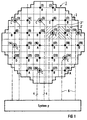
- FIG. 1 schematically shows a cross section 1 through a reactor core, in which square fuel 2 checkerboard-like stand close together.
- four such fuel assemblies form a square, at at only one corner at a time with one of the (1), (2) .. (28) designated measuring lances are arranged.
- Such Measuring probe is therefore usually at the common corner of four contiguous squares of four each Fuel assemblies arranged.
- For the evaluation of the signals these measuring lances are - again with the exception of marginal areas - four such squares each for an "area" (e.g. the neighboring, differently hatched areas 2 ', 2' ') combined, which is almost like a checkerboard cover the entire area of the core.
- area e.g. the neighboring, differently hatched areas 2 ', 2' '
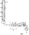
- Every measuring probe (Position 3 in FIG. 2) four each in a cladding tube 5 sensors 4a, 4b, 4c and 4d arranged one above the other, are over the corresponding measuring lines 6 of the measuring lances (1) .. (28) four sensor signals each to the entire device supplied to monitor the core. Each of these test leads 6 thus carries the sensor signals assigned to an area.
- the corresponding monitor that monitors the core thus contains only systems that are independent of each other (no Sensor signal is processed in more than one system) and the areas they monitor do not overlap. At Failure of a measuring probe will then cover an entire area 16 fuel elements are no longer monitored, but only of them affects one of the redundant systems while the other systems are not affected by this failure. Sensors in neighboring areas are always different Assigned to systems. These principles are too with other core configurations (e.g. larger cores) and the measuring lances (e.g. 34 instead of 28 measuring lances).
- Each sensor signal is initially in its area channel using subjected to a selection stage 8 of a plausibility check, whereby sensor signals are initially excreted, those outside the proper working range of the sensors lie, as this also in the already mentioned EP-A-0 496 551 is provided. From the remaining output signals from properly working sensors however - in contrast to this prior art - only one Minimum number (here: two) selected, usually the signals from the lowest available sensors. In general, the signals differ from linear sensors arranged one above the other only slightly and in particular they show practically no phase shift same, on the local power pulsation in this area to be traced back over time. The sensors can therefore in principle replace each other.
- this can be fed by the sensor signals Selection stage 8 an analog filter 9 'for the sensor signals be upstream, the selection of the two for further processing released sensor signals by a "2" 4 "selection 10 (" 2 out of 4 ") can be done simultaneously a conversion of the analog input signals into digital output signals can make so that instead of the upstream analog filter 9 'also followed by a digital filter 9 can be.
- this filter 9 also Summation of the two output signals of selection stage 8, one about the distribution of specimens of the individual Sensors averaged instantaneous value for the flow in the corresponding Area.
- the current unit is used in a standardization unit Signal A (t) at the output of filter 9 is a current measured value A (t) -A * formed which e.g. to the middle signal level A * of this range can be normalized.
- This middle level can, as described in the prior art, be formed by an integrator 10 in that the over a relatively long integration period Signal A (t) is integrated.
- This standardization delivers an alternating positive and negative measured value, so that the Oscillation amplitudes are symmetrical around a zero point and are easy to grasp.
- a digital signal processing but also makes it possible with little effort, even with differently standardized ones or non-normalized signals S, each the amplitude a half-period, which will be advantageous can set limit values as absolute values instead of relative values can be.
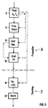
- the area channel of a system p contains an evaluation stage 12, in which the time T n is initially recorded in a first calculation stage, at which a signal value S which initially rises and is above the noise limit Ao has risen to an extreme value A n and again drops (positive peak).
- a negative peak is also detected as peak A n and its time T n , ie an extreme value lying beyond the noise limit Ao, which is formed by an initially decreasing then increasing (negative) value of the signal S.
- This extreme value detection 13 is followed by a further plausibility monitor 14, which is designed, for example, as described in EP-A-0 496 551 and checks whether the time interval DT n that can be detected in the extreme value monitor 13 between the currently recorded time T n and the previously recorded time T n-1 can correspond to an oscillation which lies within the critical frequency band between 0.3 and 0.7 Hz.
- a further evaluation element 15 advantageously additionally checks whether the recorded time interval DT n practically coincides with the last recorded time interval DT n-1 . If this is not the case, the peaks recorded are not the amplitudes of an oscillation which is practically not damped and which could rise to dangerous extreme values; further evaluation of the last peak A n determined is then suppressed.
- a subsequent computing element 16 is activated by a corresponding confirmation signal ("confirmation signal"), which calculates the "decay rate” from the peaks last determined.
- confirmation signal (
- Monitoring unit 17 (“checking") now forms Monitoring member 18 according to predetermined, in the following more precisely described monitoring criteria a signal that e.g. as a binary signal in the state "0" indicates that none of the Dangerous oscillation corresponding to monitoring criteria is present while the state "1" of the corresponding monitoring signal triggers an alarm (position 19).
- This Alarm signal can, along with other information e.g. identify the area in which the surveillance criterion has addressed, output to a display unit and / or in a memory for documenting the process to be laid down.
- the linear alarm area signals represent an M p times binary signal corresponding to the number M p of area channels, from which an N mp times binary signal is formed in an area selection stage 20 to indicate that a bit corresponding to an alarm has been set in at least a number N mp of the areas of this system.
- a corresponding alarm bit should only be set in the area signal when the monitoring criterion is met in at least two areas of the system in order to rule out a false alarm due to processing errors.
- a system selection is now made in an output stage 24, which sets an alarm end signal each time out of the total number P of the systems at least a minimum number Np set alarm signal contains.
- the system shown in FIGS and 3 illustrated processing elements of the area channel through a central computer with its own power supply, a central processor unit, an input module for 32 analog input signals and a corresponding one Output module for 32 digital output signals can be realized that at a working frequency of 32 MHz with parallel processing of the 28 sensor signals in the 32-bit input of the computer are included, about 50% full is.
- An advantageous sampling rate for the input signals is 50 Hz or more, but at least 20 Hz.
- the usual Processing elements for the sensor signals offer enough Parking space for the processor units of the systems.
- the output signals of these system processors can be sent to one commercially available microcomputer in which the received area signals are processed and stored.
- This processor also contains the programs that are required are to make the system selection and according to predetermined Strategies to deliver the signals to the reactor controller to carry out the respective stabilization measures required are.
- connecting lines can glass fibers are advantageously used.
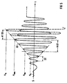
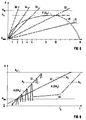
- a course of the relative range measurement value S is assumed in FIG. 5, without taking into account a scale corresponding to the actual conditions, from whose values above the noise limit A o the decay rate DA is determined if this oscillation exceeds a limit value A lim .
- the curve 30 of FIG. 6 corresponds to the extreme case represented by curve 30 in FIG. 5, 6 further curves 34, 33, 32 and 31 being indicated in this figure, the rate of increase DA of which is in each case a factor of 1/2, 1/3, 1/4 and 1/5 are lower. It can be seen from FIG. 6 that at these decay rates, a SCRAM which would be triggered if the limit value A max was exceeded is not required, but rather the time or number N 'of the oscillation periods DT required for the effectiveness of the SCRAM allows the reactor to continue operating a certain number N of periods which result from the intersection of curves 32, 33 .. with curve F (A4).
- FIG. 5 shows the relationship between the decay rates DA and the period N given by the curve F (A4), which are still available after the limit value A max has been exceeded before the initiation of a SCRAM as a corresponding limit curve F (DA).
- a curve can be determined - taking into account a sufficient safety reserve - from model calculations for the behavior of the reactor in transient conditions and from the comparison of such model calculations with actually observed reactor conditions and stored, for example, as a characteristic curve in a memory.
- the limit value A lim is exceeded, it is then sufficient to use the detected rate of decay in order to take the corresponding value N (for the curves 31, 32, 33, 34, the values N1, N2, N3, N4).
- a counter can then be set to the corresponding value N, which is counted down with each confirmation signal "confirmation" (FIG. 3).
- the reactor operation then need not be interrupted by a total SCRAM as long as the counter reading has not been counted down to zero. Even then, the total SCRAM does not need to be initiated until the amplitude limit A4 has been reached.
- the oscillation is already damped and subsides again within this time, which can be ensured in particular if an alarm signal is set when the limit value A max is exceeded, which in this alarm level only prevents changes in the control of the operating state, which could lead to an increase in performance and thus to a further transient excitation of the oscillation.
- the reactor operation continue to run for a number N2 of oscillation periods leave, it may be advantageous to prevent that the reactor is controlled to an operating state of increased power becomes.
- the duration for this Reactor operation limited to a number N3 of reactor periods are also provided to improve damping can be part of the control rods slowly into the Retracting the reactor, resulting in a reduction in reactor output corresponds to how it is operationally intended if the Lower power is demanded reactor.
- the limits DA3 and DA4 for the decay rate determine an alarm level III, in which the reactor still has a number N4 of periods can continue to run, it can also be provided to quickly retract part of the absorber rods here (as "partial SCRAM"). Only when exceeding the Limit DA4 then appears in a high-ranking alarm level a total SCRAM required.
- FIG. 8 shows decay rates for the amplitudes of the relative range signal S which correspond to curves 32 and 33 in FIG. These amplitudes are determined at the point in time at which they exceed the limit A lim . It is assumed that alarm level II has been detected by the monitoring level and a stabilization strategy has been initiated in which the reactor output is to be stabilized by slowly retracting the control rods. In the case of curve 33, the amplitudes occurring under these conditions are indicated by solid lines.
- the stabilization strategy corresponding to alarm level II - if it were also maintained at amplitude values that are above a limit value indicated by A3 and is represented by peaks drawn in broken lines - would mean that a total SCRAM would have to be initiated with the limit value A4. Such a total SCRAM should be avoided. Therefore, when the limit A3 is reached, the stabilization strategy (slow retraction of absorber elements) discussed in connection with alarm level II in FIG. 7 is switched to a higher alarm level with a higher-level stabilization strategy, namely the "partial SCRAM" mentioned. As a result, the oscillation is now dampened more, so that the amplitudes do not continue to increase, ie the limit value A4 is not reached and the total SCRAM is not initiated.
- Curve 32 shows that even in this case at a lower one Decay rate the limit A3 can be set higher than with a higher decay rate.
- the decay rate is not exceeded monitored by limit values, rather it is currently detected decay rate used to set a limit for specify the amplitude values yourself.
- the dependence of the The decay rate limit in turn, can be changed a calibration curve, similar to Figure 7, or it can also be divided up accordingly for the Decay rate of available area in individual Alarm levels, the corresponding limit A3 is gradually changed become.
- This variant has the advantage that changes in the decay rate that occur during reactor operation even after the limit value A lim have been exceeded are taken into particular account. This is shown in curve 40 of FIG. 8, in which it is initially assumed that the oscillation increases so weakly when the limit value A lim is exceeded that intervention in the reactor control system is not necessary. However, it is assumed that the operating personnel at time t b increased the output by means of the operational reactor control, by means of which the transiently excited oscillation is considerably increased.
- Analogous to the limit value A3 for the amplitude A which is the introduction of the partial SCRAM can, of course, also for the lower ranking stabilization strategies (blocking one Performance increase, alarm level I; or slowly introducing additional ones Absorber elements, alarm level II) a corresponding Limit A1 and A2 are introduced.
- the curve 42 shown in FIG. 10 is based on a relatively high ringing rate DA, which is why the limit values A1, A2 and A3 in this case - depending on the dedicated ringing rate DA - are set lower than in FIG. 9. Therefore, the alarm level II (limit value A2) is reached relatively early and the "partial SCRAM" provided by exceeding limit A3 in alarm stage III is also carried out earlier. This leads to the desired damping of the oscillation and prevents the limit value A max from being exceeded. This prevents a total shutdown even in this unfavorable case.
- the respective alarm levels can be reset, for example, when the amplitude again falls below the limit value A lim .
- FIG. 11 shows an embodiment for the monitoring in FIG the system 1 command channels, the range selection level for the alarm signals that are in the area signal through this Monitoring can be set, and the monitoring device in the corresponding system channel.
- This limit value is a memory 52 for a characteristic curve taken. According to the stored characteristic curve this limit value A1 corresponds to that in area channel 1 (position 16, FIG 3) determined value DA of the current decay rate.
- a display and / or storage unit 53 is controlled are now for the monitoring signal AA1, that of the first Alarm level and the first area channel is assigned alarm area signal AA1 assigned to the first alarm level forms.
- the relative range signal S in an evaluation unit (not shown) with regard to the limit value A2 and one the limit value detector 55, the characteristic curve memory 56 and the display and / or storage unit 57 containing surveillance level regarding limit A3 and alarm level III. Not it is shown that the signal S by means of another Limit detector for exceeding a predefined limit Limit A4 can be monitored.
- That of the limit indicators 51, 51 'in the individual area channels formed monitoring signals can be summed in a summing element 60 become.
- This signal therefore indicates in how many area channels the corresponding limit indicator 51 an alarm signal who has set level I. Is this number larger or equal to a predetermined number of Nmp, a corresponding number Interrogation unit 61 a corresponding alarm system signal.
- the query unit 61 takes this query twice before, whereby for a first alarm system signal AA1 ' the minimum number Nmp is set to 1.
- This signal AA1 ' can then be used to make an appropriate system selection (In the simplest case, a summing element (not shown) for all signals AA1 'from all redundant ones System channels) to indicate whether and how many systems the Generate alarm level I.
- Nmp 2 is also set in this system monitoring 61, So a corresponding signal AA1 '' is output if report the level I alarm to at least two areas.
- This Signal can be used to select from all in the system selection Alarm signals generated in the redundant systems are to form an alarm end signal that is in the control of the reactor can intervene and there an operational Blocked increase in reactor output. In the simplest In this case, it is sufficient if the system selection only shows a "1 out of 4" Selection forms, i.e. the corresponding signals AA1 '' four systems combined by an "OR" element.
- the monitoring signals assigned to alarm levels II and III of the individual areas of the system to corresponding signals are processed in the query units 65, 66 for Generation of the alarm system signals assigned to these stages Deliver AA3 'and AA3' '.
- the from the alarm signals AA2 '' of Four system signals are generated in the same way as on the occasion the signals AA1 '' has been processed (not shown) and form an assigned to this alarm level II End-of-alarm signal, so in reactor operation intervenes that not only ramping up the reactor power blocked, but even the reactor power according to the programs, which are intended for normal reactor operation, is shut down.
- the invention thus ensures on the one hand that the unstable state of the reactor is monitored with sufficient redundancy in order to be able to make a reliable statement about the unstable state in the event of failure of individual sensors, measuring lances or computing elements, and on the other hand it is also achieved that the instability is damped intervention in the reactor operation is only to a small extent.
- a total SCRAM is practically excluded according to all experience and estimates, so that on the fourth alarm level, the strategy of which provides for a total SCRAM, can be regarded as completely unnecessary.
- the components provided for monitoring the limit value A max and the transmission elements for an alarm signal assigned to this highest alarm level are therefore only described as an option, which can also be dispensed with.
Landscapes
- Physics & Mathematics (AREA)
- Engineering & Computer Science (AREA)
- Plasma & Fusion (AREA)
- General Engineering & Computer Science (AREA)
- High Energy & Nuclear Physics (AREA)
- Chemical & Material Sciences (AREA)
- Chemical Kinetics & Catalysis (AREA)
- Monitoring And Testing Of Nuclear Reactors (AREA)
- Safety Devices In Control Systems (AREA)
Applications Claiming Priority (3)
| Application Number | Priority Date | Filing Date | Title |
|---|---|---|---|
| DE19500395 | 1995-01-09 | ||
| DE19500395A DE19500395A1 (de) | 1995-01-09 | 1995-01-09 | Verfahren und Vorrichtung zum Betrieb eines Reaktors im instabilen Zustand |
| EP96900255A EP0803125A1 (fr) | 1995-01-09 | 1996-01-08 | Procede et dispositif permettant de faire fonctionner un reacteur dans un etat instable |
Related Parent Applications (1)
| Application Number | Title | Priority Date | Filing Date |
|---|---|---|---|
| EP96900255A Division EP0803125A1 (fr) | 1995-01-09 | 1996-01-08 | Procede et dispositif permettant de faire fonctionner un reacteur dans un etat instable |
Publications (2)
| Publication Number | Publication Date |
|---|---|
| EP0928007A1 true EP0928007A1 (fr) | 1999-07-07 |
| EP0928007B1 EP0928007B1 (fr) | 2003-10-08 |
Family
ID=7751150
Family Applications (2)
| Application Number | Title | Priority Date | Filing Date |
|---|---|---|---|
| EP98123358A Expired - Lifetime EP0928007B1 (fr) | 1995-01-09 | 1996-01-08 | Procédé de conduite d'un réacteur dans des conditions de fonctionnement instable et système adapté à sa mise en oeuvre |
| EP96900255A Ceased EP0803125A1 (fr) | 1995-01-09 | 1996-01-08 | Procede et dispositif permettant de faire fonctionner un reacteur dans un etat instable |
Family Applications After (1)
| Application Number | Title | Priority Date | Filing Date |
|---|---|---|---|
| EP96900255A Ceased EP0803125A1 (fr) | 1995-01-09 | 1996-01-08 | Procede et dispositif permettant de faire fonctionner un reacteur dans un etat instable |
Country Status (6)
| Country | Link |
|---|---|
| US (3) | US5875221A (fr) |
| EP (2) | EP0928007B1 (fr) |
| JP (3) | JP4063867B2 (fr) |
| DE (2) | DE19500395A1 (fr) |
| ES (1) | ES2206814T3 (fr) |
| WO (1) | WO1996021929A1 (fr) |
Families Citing this family (14)
| Publication number | Priority date | Publication date | Assignee | Title |
|---|---|---|---|---|
| US5528639A (en) † | 1994-08-01 | 1996-06-18 | General Electric Company | Enhanced transient overpower protection system |
| JP3875838B2 (ja) * | 1998-04-28 | 2007-01-31 | アレヴァ エンペー ゲゼルシャフト ミット ベシュレンクテル ハフツング | 原子炉始動時の出力上昇を監視するための方法および装置 |
| SE521873C2 (sv) * | 1998-08-25 | 2003-12-16 | Toshiba Kk | Ett i härden fast anordnat kärnenergiinstrumentsystem |
| RU2181510C1 (ru) * | 2001-07-27 | 2002-04-20 | Дурнев Владимир Николаевич | Способ управления ядерной энергетической установкой |
| DE10159432A1 (de) * | 2001-12-04 | 2003-06-26 | Framatome Anp Gmbh | Steuerungssystem für eine Kernkraftwerksanlage sowie Verfahren zum Betreiben einer Kernkraftwerksanlage |
| US8135106B2 (en) * | 2004-04-23 | 2012-03-13 | Areva Np Inc. | Protection of reactor cores from unstable density wave oscillations |
| DE102005058192A1 (de) * | 2005-12-06 | 2007-06-28 | Airbus Deutschland Gmbh | Vorrichtung zur Fehlererkennung von verstellbaren Klappen |
| JP2007240464A (ja) * | 2006-03-10 | 2007-09-20 | Toshiba Corp | 沸騰水型原子炉炉心状態監視装置 |
| CN101840740B (zh) * | 2009-06-19 | 2012-10-03 | 中广核工程有限公司 | 一种两通道故障自动检测系统及检测方法 |
| US9177676B2 (en) | 2010-05-14 | 2015-11-03 | Kabushiki Kaisha Toshiba | Nuclear reactor power monitor |
| EP2581914B1 (fr) * | 2011-10-10 | 2014-12-31 | Ion Beam Applications S.A. | Procédé et installation pour la production d'un radioisotope |
| CN105161143A (zh) * | 2014-05-29 | 2015-12-16 | 江苏核电有限公司 | 一种反应堆物理启动期间增效节能的综合方法 |
| US11227697B2 (en) * | 2018-10-29 | 2022-01-18 | Framatome Inc. | Self-powered in-core detector arrangement for measuring flux in a nuclear reactor core |
| CN110428919B (zh) * | 2019-07-08 | 2023-01-17 | 中国核电工程有限公司 | 基于征兆的压水堆核电厂反应性控制策略的设计方法 |
Citations (8)
| Publication number | Priority date | Publication date | Assignee | Title |
|---|---|---|---|---|
| DD132457A1 (de) * | 1977-08-01 | 1978-09-27 | Klaus Meyer | Verfahren zur ueberwachung von schwingungen von spaltzonenelementen in kernreaktoren |
| JPS59196499A (ja) * | 1983-04-22 | 1984-11-07 | 日本原子力事業株式会社 | 沸騰水型原子炉の炉心安定性監視方法 |
| JPS60159691A (ja) * | 1984-01-31 | 1985-08-21 | 株式会社東芝 | 原子炉運転制御装置 |
| JPS6275295A (ja) * | 1985-09-28 | 1987-04-07 | 株式会社東芝 | 原子炉の局所振動監視装置 |
| EP0496551A1 (fr) * | 1991-01-22 | 1992-07-29 | General Electric Company | Méthode et système de surveillance du champs d'oscillation de la puissance pour réacteurs nucléaires |
| WO1993007623A1 (fr) * | 1991-09-30 | 1993-04-15 | Combustion Engineering, Inc. | Detection des oscillations hydrauliques d'origine thermique survenant dans le c×ur d'un reacteur nucleaire |
| JPH0694882A (ja) * | 1992-09-11 | 1994-04-08 | Japan Atom Energy Res Inst | 原子炉出力の不安定性監視方法 |
| US5406598A (en) * | 1992-09-22 | 1995-04-11 | Kabushiki Kaisha Toshiba | System for monitoring power of nuclear reactor |
Family Cites Families (1)
| Publication number | Priority date | Publication date | Assignee | Title |
|---|---|---|---|---|
| US5141710A (en) * | 1991-06-24 | 1992-08-25 | General Electric Company | Reactivity modulation of a boiling water reactor to stabilize thermal-hydraulic instabilities |
-
1995
- 1995-01-09 DE DE19500395A patent/DE19500395A1/de not_active Withdrawn
-
1996
- 1996-01-08 JP JP52136496A patent/JP4063867B2/ja not_active Expired - Lifetime
- 1996-01-08 EP EP98123358A patent/EP0928007B1/fr not_active Expired - Lifetime
- 1996-01-08 EP EP96900255A patent/EP0803125A1/fr not_active Ceased
- 1996-01-08 ES ES98123358T patent/ES2206814T3/es not_active Expired - Lifetime
- 1996-01-08 WO PCT/DE1996/000014 patent/WO1996021929A1/fr not_active Ceased
- 1996-01-08 DE DE59610767T patent/DE59610767D1/de not_active Expired - Lifetime
-
1997
- 1997-07-09 US US08/890,258 patent/US5875221A/en not_active Expired - Lifetime
-
1998
- 1998-11-04 US US09/186,000 patent/US6122339A/en not_active Expired - Lifetime
- 1998-11-04 US US09/185,848 patent/US5978429A/en not_active Expired - Lifetime
-
2005
- 2005-05-23 JP JP2005149151A patent/JP4252048B2/ja not_active Expired - Fee Related
- 2005-05-23 JP JP2005149150A patent/JP4361035B2/ja not_active Expired - Fee Related
Patent Citations (8)
| Publication number | Priority date | Publication date | Assignee | Title |
|---|---|---|---|---|
| DD132457A1 (de) * | 1977-08-01 | 1978-09-27 | Klaus Meyer | Verfahren zur ueberwachung von schwingungen von spaltzonenelementen in kernreaktoren |
| JPS59196499A (ja) * | 1983-04-22 | 1984-11-07 | 日本原子力事業株式会社 | 沸騰水型原子炉の炉心安定性監視方法 |
| JPS60159691A (ja) * | 1984-01-31 | 1985-08-21 | 株式会社東芝 | 原子炉運転制御装置 |
| JPS6275295A (ja) * | 1985-09-28 | 1987-04-07 | 株式会社東芝 | 原子炉の局所振動監視装置 |
| EP0496551A1 (fr) * | 1991-01-22 | 1992-07-29 | General Electric Company | Méthode et système de surveillance du champs d'oscillation de la puissance pour réacteurs nucléaires |
| WO1993007623A1 (fr) * | 1991-09-30 | 1993-04-15 | Combustion Engineering, Inc. | Detection des oscillations hydrauliques d'origine thermique survenant dans le c×ur d'un reacteur nucleaire |
| JPH0694882A (ja) * | 1992-09-11 | 1994-04-08 | Japan Atom Energy Res Inst | 原子炉出力の不安定性監視方法 |
| US5406598A (en) * | 1992-09-22 | 1995-04-11 | Kabushiki Kaisha Toshiba | System for monitoring power of nuclear reactor |
Non-Patent Citations (4)
| Title |
|---|
| DATABASE WPI Section Ch Week 8451, Derwent World Patents Index; Class K05, AN 84-314887, XP002098613 * |
| DATABASE WPI Section Ch Week 8540, Derwent World Patents Index; Class K05, AN 85-245097, XP002098612 * |
| DATABASE WPI Section Ch Week 8719, Derwent World Patents Index; Class K05, AN 87-133519, XP002098611 * |
| PATENT ABSTRACTS OF JAPAN vol. 018, no. 356 (P - 1765) 5 July 1994 (1994-07-05) * |
Also Published As
| Publication number | Publication date |
|---|---|
| EP0803125A1 (fr) | 1997-10-29 |
| DE19500395A1 (de) | 1996-07-18 |
| JP4252048B2 (ja) | 2009-04-08 |
| JP4361035B2 (ja) | 2009-11-11 |
| US6122339A (en) | 2000-09-19 |
| DE59610767D1 (de) | 2003-11-13 |
| EP0928007B1 (fr) | 2003-10-08 |
| WO1996021929A1 (fr) | 1996-07-18 |
| JP4063867B2 (ja) | 2008-03-19 |
| ES2206814T3 (es) | 2004-05-16 |
| JP2005283597A (ja) | 2005-10-13 |
| JP2005241657A (ja) | 2005-09-08 |
| JPH10512051A (ja) | 1998-11-17 |
| US5978429A (en) | 1999-11-02 |
| US5875221A (en) | 1999-02-23 |
Similar Documents
| Publication | Publication Date | Title |
|---|---|---|
| EP0928007B1 (fr) | Procédé de conduite d'un réacteur dans des conditions de fonctionnement instable et système adapté à sa mise en oeuvre | |
| DE69022305T2 (de) | Automatisierte Überwachung einer thermischen Schwelle. | |
| DE69404557T2 (de) | Verfahren zur Überwachung und zur Fehlererkennung einer Anlage | |
| DE60016843T2 (de) | Verfahren und Einrichtung zum Erkennen der Kritikalitätsnähe in einem unter Verwendung von Kernbrennstoff betriebenen elektrischen Kraftwerk | |
| EP2092499B1 (fr) | Procédés et dispositif pour optimiser une configuration d'alarme | |
| DE3152560C2 (de) | Verfahren und Vorrichtung zur Verarbeitung eines Schwankungen unterworfenen Meßsignals | |
| DE69201969T2 (de) | Verfahren und System zur Überwachung des Leistungsschwankungsbandes für Kernreaktoren. | |
| DE2535654C2 (fr) | ||
| DE19941403B4 (de) | Neutronenflußmeßvorrichtung | |
| DE2941544A1 (de) | Verfahren zum aufrechterhalten des fluidstandes in einem mit fluid gefuellten behaelter | |
| DE2531396C3 (de) | Anordnung zur Regelung der Ausgangsleistung eines Siedewasserkernreaktors | |
| SE513236C2 (sv) | System för effektövervakning i en kärnreaktor | |
| DE69505209T2 (de) | Im Übergangsbetrieb eingestelltes Überleistungschutzsystem | |
| DE69209383T2 (de) | Reaktivitätsmodulation eines Siedewasserreaktors zur Stabilisierung von thermohydraulischen Schwingungen | |
| EP0796495A2 (fr) | Procede et systeme de commande de barres de commande d'une centrale nucleaire | |
| DE68907651T2 (de) | Verfahren und Vorrichtung zur Feststellung einer gefallenen Regelstabspinne eines Kernreaktors. | |
| DE68906714T2 (de) | Verfahren zur Bestimmung und Abschätzung der Notabschaltreserve eines Druckwasserkernreaktors. | |
| DE1474032A1 (de) | Geraet zur Programmunterbrechung und zur Ausloesung eines Unterprogramms in einem digitalen Prozessrechner | |
| DE60212376T2 (de) | System zur vorsehbaren diagnose in einer speicher programmierbaren steuerung | |
| EP1075696B1 (fr) | Procede et dispositif pour surveiller la montee en puissance lors du demarrage d'un reacteur nucleaire (surveillance d'excursion diversitaire) | |
| DE4412024A1 (de) | Solarkollektor mit Störungsüberwachung | |
| EP1595264B1 (fr) | Procede de mesure d'une grandeur relative de la combustion d'elements combustibles d'un reacteur haute temperature a lit de boules, et dispositif associe | |
| DE2810917A1 (de) | Verfahren zur ueberwachung und begrenzung der lokalen leistungsdichte in kernreaktoren | |
| DE2624321C2 (de) | Verfahren und Vorrichtung zum Kontrollieren der Funktionsfähigkeit eines in einer Sicherheitsanordnung enthaltenen Meßkanals | |
| DE2653411A1 (de) | Kernreaktor und verfahren zur ermittlung der leistungsverteilung im reaktorkern |
Legal Events
| Date | Code | Title | Description |
|---|---|---|---|
| PUAI | Public reference made under article 153(3) epc to a published international application that has entered the european phase |
Free format text: ORIGINAL CODE: 0009012 |
|
| AC | Divisional application: reference to earlier application |
Ref document number: 803125 Country of ref document: EP |
|
| AK | Designated contracting states |
Kind code of ref document: A1 Designated state(s): CH DE ES LI SE |
|
| 17P | Request for examination filed |
Effective date: 19991217 |
|
| RAP1 | Party data changed (applicant data changed or rights of an application transferred) |
Owner name: FRAMATOME ANP GMBH |
|
| GRAH | Despatch of communication of intention to grant a patent |
Free format text: ORIGINAL CODE: EPIDOS IGRA |
|
| GRAS | Grant fee paid |
Free format text: ORIGINAL CODE: EPIDOSNIGR3 |
|
| GRAA | (expected) grant |
Free format text: ORIGINAL CODE: 0009210 |
|
| AC | Divisional application: reference to earlier application |
Ref document number: 0803125 Country of ref document: EP Kind code of ref document: P |
|
| AK | Designated contracting states |
Kind code of ref document: B1 Designated state(s): CH DE ES LI SE |
|
| REG | Reference to a national code |
Ref country code: CH Ref legal event code: EP |
|
| REF | Corresponds to: |
Ref document number: 59610767 Country of ref document: DE Date of ref document: 20031113 Kind code of ref document: P |
|
| REG | Reference to a national code |
Ref country code: CH Ref legal event code: NV Representative=s name: DR. R.C. SALGO & PARTNER |
|
| REG | Reference to a national code |
Ref country code: SE Ref legal event code: TRGR |
|
| REG | Reference to a national code |
Ref country code: ES Ref legal event code: FG2A Ref document number: 2206814 Country of ref document: ES Kind code of ref document: T3 |
|
| PLBE | No opposition filed within time limit |
Free format text: ORIGINAL CODE: 0009261 |
|
| STAA | Information on the status of an ep patent application or granted ep patent |
Free format text: STATUS: NO OPPOSITION FILED WITHIN TIME LIMIT |
|
| 26N | No opposition filed |
Effective date: 20040709 |
|
| REG | Reference to a national code |
Ref country code: CH Ref legal event code: PFA Owner name: AREVA NP GMBH Free format text: FRAMATOME ANP GMBH#FREYESLEBENSTRASSE 1#91050 ERLANGEN (DE) -TRANSFER TO- AREVA NP GMBH#FREYESLEBENSTRASSE 1#91058 ERLANGEN (DE) |
|
| REG | Reference to a national code |
Ref country code: CH Ref legal event code: PFA Owner name: AREVA NP GMBH Free format text: AREVA NP GMBH#FREYESLEBENSTRASSE 1#91058 ERLANGEN (DE) -TRANSFER TO- AREVA NP GMBH#FREYESLEBENSTRASSE 1#91058 ERLANGEN (DE) |
|
| REG | Reference to a national code |
Ref country code: CH Ref legal event code: PCOW Free format text: AREVA NP GMBH;PAUL-GOSSEN-STRASSE 100;91052 ERLANGEN (DE) |
|
| REG | Reference to a national code |
Ref country code: DE Ref legal event code: R082 Ref document number: 59610767 Country of ref document: DE Representative=s name: MEISSNER BOLTE & PARTNER GBR, DE Effective date: 20131212 Ref country code: DE Ref legal event code: R082 Ref document number: 59610767 Country of ref document: DE Representative=s name: MOERTEL, ALFRED, DIPL.-PHYS. DR.RER.NAT., DE Effective date: 20131212 Ref country code: DE Ref legal event code: R081 Ref document number: 59610767 Country of ref document: DE Owner name: AREVA GMBH, DE Free format text: FORMER OWNER: AREVA NP GMBH, 91052 ERLANGEN, DE Effective date: 20131212 |
|
| REG | Reference to a national code |
Ref country code: DE Ref legal event code: R082 Ref document number: 59610767 Country of ref document: DE Representative=s name: MEISSNER BOLTE & PARTNER GBR, DE |
|
| PGFP | Annual fee paid to national office [announced via postgrant information from national office to epo] |
Ref country code: SE Payment date: 20140123 Year of fee payment: 19 Ref country code: DE Payment date: 20140123 Year of fee payment: 19 Ref country code: CH Payment date: 20140124 Year of fee payment: 19 |
|
| PGFP | Annual fee paid to national office [announced via postgrant information from national office to epo] |
Ref country code: ES Payment date: 20140122 Year of fee payment: 19 |
|
| REG | Reference to a national code |
Ref country code: DE Ref legal event code: R119 Ref document number: 59610767 Country of ref document: DE |
|
| REG | Reference to a national code |
Ref country code: CH Ref legal event code: PL |
|
| REG | Reference to a national code |
Ref country code: SE Ref legal event code: EUG |
|
| PG25 | Lapsed in a contracting state [announced via postgrant information from national office to epo] |
Ref country code: DE Free format text: LAPSE BECAUSE OF NON-PAYMENT OF DUE FEES Effective date: 20150801 Ref country code: CH Free format text: LAPSE BECAUSE OF NON-PAYMENT OF DUE FEES Effective date: 20150131 Ref country code: LI Free format text: LAPSE BECAUSE OF NON-PAYMENT OF DUE FEES Effective date: 20150131 |
|
| PG25 | Lapsed in a contracting state [announced via postgrant information from national office to epo] |
Ref country code: SE Free format text: LAPSE BECAUSE OF NON-PAYMENT OF DUE FEES Effective date: 20150109 |
|
| REG | Reference to a national code |
Ref country code: ES Ref legal event code: FD2A Effective date: 20160226 |
|
| PG25 | Lapsed in a contracting state [announced via postgrant information from national office to epo] |
Ref country code: ES Free format text: LAPSE BECAUSE OF NON-PAYMENT OF DUE FEES Effective date: 20150109 |