EP0928539B1 - Television comportant un decodeur recepteur integre - Google Patents
Television comportant un decodeur recepteur integre Download PDFInfo
- Publication number
- EP0928539B1 EP0928539B1 EP97909867A EP97909867A EP0928539B1 EP 0928539 B1 EP0928539 B1 EP 0928539B1 EP 97909867 A EP97909867 A EP 97909867A EP 97909867 A EP97909867 A EP 97909867A EP 0928539 B1 EP0928539 B1 EP 0928539B1
- Authority
- EP
- European Patent Office
- Prior art keywords
- signal
- television
- circuitry
- switch
- mixer
- Prior art date
- Legal status (The legal status is an assumption and is not a legal conclusion. Google has not performed a legal analysis and makes no representation as to the accuracy of the status listed.)
- Expired - Lifetime
Links
- 238000000034 method Methods 0.000 claims description 21
- 230000008569 process Effects 0.000 claims description 20
- 239000003086 colorant Substances 0.000 claims description 2
- 230000005540 biological transmission Effects 0.000 abstract description 4
- RRLHMJHRFMHVNM-BQVXCWBNSA-N [(2s,3r,6r)-6-[5-[5-hydroxy-3-(4-hydroxyphenyl)-4-oxochromen-7-yl]oxypentoxy]-2-methyl-3,6-dihydro-2h-pyran-3-yl] acetate Chemical compound C1=C[C@@H](OC(C)=O)[C@H](C)O[C@H]1OCCCCCOC1=CC(O)=C2C(=O)C(C=3C=CC(O)=CC=3)=COC2=C1 RRLHMJHRFMHVNM-BQVXCWBNSA-N 0.000 description 19
- 230000033001 locomotion Effects 0.000 description 9
- 239000011159 matrix material Substances 0.000 description 7
- 230000001934 delay Effects 0.000 description 6
- 238000013478 data encryption standard Methods 0.000 description 5
- 230000006870 function Effects 0.000 description 5
- 230000005236 sound signal Effects 0.000 description 5
- 230000002123 temporal effect Effects 0.000 description 4
- 230000000007 visual effect Effects 0.000 description 4
- 101100322245 Caenorhabditis elegans des-2 gene Proteins 0.000 description 3
- 238000005070 sampling Methods 0.000 description 3
- 238000006243 chemical reaction Methods 0.000 description 2
- 230000001360 synchronised effect Effects 0.000 description 2
- 101100100074 Caenorhabditis elegans tpp-2 gene Proteins 0.000 description 1
- 108010076504 Protein Sorting Signals Proteins 0.000 description 1
- 230000003321 amplification Effects 0.000 description 1
- 230000008901 benefit Effects 0.000 description 1
- 230000010354 integration Effects 0.000 description 1
- 238000012986 modification Methods 0.000 description 1
- 230000004048 modification Effects 0.000 description 1
- 238000003199 nucleic acid amplification method Methods 0.000 description 1
- 230000035755 proliferation Effects 0.000 description 1
- 230000009467 reduction Effects 0.000 description 1
- 238000000926 separation method Methods 0.000 description 1
Images


Classifications
-
- H—ELECTRICITY
- H04—ELECTRIC COMMUNICATION TECHNIQUE
- H04N—PICTORIAL COMMUNICATION, e.g. TELEVISION
- H04N7/00—Television systems
- H04N7/01—Conversion of standards, e.g. involving analogue television standards or digital television standards processed at pixel level
-
- H—ELECTRICITY
- H04—ELECTRIC COMMUNICATION TECHNIQUE
- H04N—PICTORIAL COMMUNICATION, e.g. TELEVISION
- H04N7/00—Television systems
- H04N7/01—Conversion of standards, e.g. involving analogue television standards or digital television standards processed at pixel level
- H04N7/0117—Conversion of standards, e.g. involving analogue television standards or digital television standards processed at pixel level involving conversion of the spatial resolution of the incoming video signal
- H04N7/0122—Conversion of standards, e.g. involving analogue television standards or digital television standards processed at pixel level involving conversion of the spatial resolution of the incoming video signal the input and the output signals having different aspect ratios
-
- H—ELECTRICITY
- H04—ELECTRIC COMMUNICATION TECHNIQUE
- H04N—PICTORIAL COMMUNICATION, e.g. TELEVISION
- H04N5/00—Details of television systems
- H04N5/44—Receiver circuitry for the reception of television signals according to analogue transmission standards
- H04N5/445—Receiver circuitry for the reception of television signals according to analogue transmission standards for displaying additional information
-
- H—ELECTRICITY
- H04—ELECTRIC COMMUNICATION TECHNIQUE
- H04N—PICTORIAL COMMUNICATION, e.g. TELEVISION
- H04N5/00—Details of television systems
- H04N5/44—Receiver circuitry for the reception of television signals according to analogue transmission standards
- H04N5/46—Receiver circuitry for the reception of television signals according to analogue transmission standards for receiving on more than one standard at will
Definitions
- the present invention relates generally to television receivers and, more particularly, to those television receivers having shared circuitry with digital receiver/decoders.
- VCR video cassette recorders
- DVD digital video disk
- DSS digital satellite system
- IRDs integrated receiver decoders
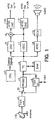
- a typical DSS IRD is shown in Figure 1.
- Digital signals from an orbiting satellite are received at antenna 110 attached to the IRD front-end 1.
- the digital signals are typical encrypted MPEG streams containing television programming as well as audio-only programming.
- the IRD front-end 1 is a tuner which allows a user to select a desired channel.
- the front-end I also provides amplification of the relatively weak signal received at antenna 110.
- switch 33 will couple the selected channel signal from front-end 1 to the transport parser (TPP) 2.
- TPP transport parser
- the DSS IRD will be connected to other elements of a home entertainment system though an interface (I/F) which may comply with the IEEE standards document 1394 entitled Standard for High Performance Serial Bus (hereafter, the "IEEE 1394 Serial Bus Standard").
- the 1394 I/F 3 may connect the DSS IRD to a variety of video cassette recorders, digital video disk players, and other audio/visual or computer components.
- digital signals from these other components can be supplied though 1394 I/F 3 across a corresponding serial bus.
- switch 33 will be oriented so as to connect TPP 2 to 1394 I/F 3.
- Transport parser 2 also includes a data encryption standard (DES) block.
- TPP/DES 2 parses and decrypts the digital bit stream received from front-end 1 (typically, signals received from 1394 I/F 3 will already be decrypted and will bypass the decryption engine in TPP/DES 2).
- the decrypted bit stream is then passed though traffic controller (TC) 4 and is stored in RAM 5.
- RAM 5 may be a 16 megabyte synchronous dynamic RAM for one embodiment.
- the decrypted bit stream from TPP/DES 2 is also transmitted to other audio/visual components, for example a digital video cassette recorder, though 1394 I/F 3.
- Traffic controller 4 distributes the stored data from RAM 5 to an appropriate decoder. This may be either video decoder 7 or audio decoder 8.
- video decoder 7 the signal is passed from RAM 5 though traffic controller 4 to video decoder (VDEC) 7 where it is decoded according to the MPEG standards.
- audio data is transferred from RAM 5 though traffic controller 4 to audio decoder (ADEC) 8 for decoding.
- DEC digital-to-analog
- Video signals are converted from a digital to an analog signal and the analog signal is encoded according to the NTSC standard in NTSC encoder 12. This NTSC signal may be transmitted to an analog video cassette recorder.
- video signals must be passed from video decoder 7 to the analog television set. Accordingly, a second NTSC encoder 100 is provided for this purpose.
- the video signals may be mixed in mixer 9 with on screen display data, such as a programming table, before being encoded.
- the on screen display data present in the MPEG stream is decoded by on screen display block 6 prior to mixing.
- Patent Abstracts of Japan, vol. 096, no. 008, 30/08/96, and Japanese Patent Application Publication No. JP-A-0 8 098 105 discloses a television having an NTSC decoder and an MPEG decoder, whose outputs can be selectively directed by a controller and a switch to a display.
- European Patent Application Publication No EP-A-0 701 367 describes a program guide interface.
- a source has an analog and a digital video signal.
- a luminance component of the analog video signal is input to a demodulator.
- the digital video signal is input to a demultiplexer.
- the program guide information is formatted into a graphics video signal.
- a multiplexer selects the graphics video signal and one of the video signals as an output video signal.
- JP-A-05 292423 an English language abstract of which appears at PAJ, vol. 018, no. 088 (E-1507), describes an NTSC decode circuit and an EDTV decode circuit.
- the NTSC decode circuit performs YC separation processing and color demodulation processing and generates a digitized three primary color signal sequence. Both circuits process the same television signal.
- the present invention provides a television according to claim 1 hereof.
- a preferred implementation of the present invention described hereinbelow provides a television set with an integrated digital receiver/decoder.
- the receiving/decoder By integrating the receiving/decoder with the television, some circuitry and memory can be shared.
- the digital video signal provided by the receiver/decoder need not be converted to an analog NTSC signal before transmission to the television. Accordingly, picture quality is less degraded than in systems utilizing standard NTSC connections.
- on screen display data is displayed without distortion.
- the first format may be, e.g., NTSC, and the second format may be, e.g., MPEG.
- the first and second circuitry may include a shared memory.
- the first circuitry may include circuitry for separating luminance and chrominance information and circuitry for using such information to generate RGB signals for display.
- the second circuitry may include MPEG decoders for video and audio data.
- a television with an integrated receiver decoder is disclosed.
- DSS IRD digital satellite system integrated receiver decoder
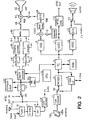
- Figure 2 illustrates one embodiment of a digital television set with an integrated receiver/decoder.
- antenna 110 receives digital signals provided by a digital satellite system service provider and outputs those signals to a tuner/front-end 1.
- Tuner/front-end 1 allows a user to select a desired channel and also amplifies the relatively weak signal provided by antenna 110.
- switch 33 is oriented so as to connect tuner/front-end 1 to TPP/DES block 2.
- the DSS IRD portion of the integrated system also provides an Interface 3 to connect to other digital audio/visual components.
- Interface 3 preferably operates according to the IEEE 1394 Serial Bus Standard, as described above. In other embodiments, however, other digital networks may be used and Interface 3 will operate accordingly.
- switch 33 is oriented so as to connect Interface 3 to the TPP/DES block 2.
- the digital signal is parsed and decrypted (if necessary) by TPP/DES block 2 and passed to traffic controller 4.
- Traffic controller 4 stores the decrypted bit stream in RAM 5. which may be a 16 megabyte synchronous dynamic RAM.
- the decrypted bit stream is also transmitted to other audio/visual components across the 1394 serial bus though Interface 3.
- Traffic controller 4 distributes the stored data in RAM 5 to video decoder 7 and audio decoder 8 as appropriate.
- Video decoder (VDEC) 7 receives video data from RAM 5 and decodes it according to the MPEG standard.
- audio decoder 8 receives audio data from RAM 5 and decodes it according to the MPEG standard.
- the decoded audio signal is passed from audio decoder 8 to digital-to-analog converter 13 where it is converted to an analog signal. This analog audio signal is then passed to a speaker system.
- Switch 14 connects the digital-to-analog converter 13 to the speaker system when the integrated system is in a receiver/decoder mode. In a television mode, switch 14 will connect the speaker system to an audio detector/amplifier 19.
- On screen display data stored in RAM 5 as part of the MPEG stream is transmitted though traffic controller 4 to the on screen display (OSD) block 6.
- OSD block 6 decodes the on screen display data, for example, a program guide, constructs the on screen display information and assigns appropriate colors to each pixel using a color look-up table.
- the on-screen display data is then mixed in mixer 9 with decoded video data from video decoder 7 for display.
- the decoded video signal from video decoder 7 is passed though expander 60 but is not expanded.
- expander 60 horizontally expands the video data provided by video decoder 7 to 16x9 format. In this case, the horizontal pixel number will be enlarged four-thirds times. Further details of the 16x9 mode are described below.
- switch 10 In receiver/decoder mode, switch 10 is closed. Accordingly, mixer 9 mixes the decoded video output from VDEC 7 and the on screen display data from OSD block 6 and passes the mixed signal to RGB converter 11. RGB converter 11 converts the digital bit stream to appropriate RGB signals for CRT 32. The RGB signals are transmitted to digital-to-analog converter 48 which converts the digital RGB signals to their analog equivalents. Switch 49 is closed and the analog RGB signals are passed to CRT 32 though mixer 47. Note that in receiver/decoder mode, switch 46 will be open so no mixing occurs in mixer 47. The resulting signal is applied to CRT 32 and video data is therebv displayed.
- CPU 15 which provides the appropriate control signals for the above operation.
- CPU 15 may also handle user interface functions though a user interface block (not shown).
- This user interface block may be front panel controls or an infra-red or other remote control. While in receiver/decoder mode, the television circuits (described below) are placed in a low power or halt mode.
- video decoder 7 While in receiver/decoder mode, the output of video decoder 7 may also be sent to NTSC encoder 12 where it is converted to an analog NTSC signal.
- This analog NTSC signal may be passed to an analog video cassette recorder to allow for recording of television programming. It should be noted that this embodiment of the present invention requires only one NTSC encoder whereas existing receiver/decoders require two NTSC encoders, as shown in Figure 1. By providing video signals directly to CRT 32, the need for a second NTSC encoder is eliminated.
- the integrated system shown in Figure 2 also has a number of traditional television circuits.
- television mode i.e., when these television circuits are in use, the receiver/decoder circuits described above will be placed in a low power or halt mode by CPU 15. In this way, power is conserved.
- a signal from an antenna 112 or cable television source 114 is first tuned to a desired channel at tuner 16 then amplified in amplifier 17 and detected in detector 18. All of these operations are conventional and well known in the art.
- Detector 18 outputs a video signal and an audio signal.
- the audio signal is detected by audio detector/amplifier 19 and passed to a speaker system though switch 14.
- the video signal from detector 18 is sampled by analog-to-digital (A/D) converter 21.
- A/D converter 21 The digital signal output from A/D converter 21 is passed to block 22 where the horizontal and vertical sync pulses are extracted and fed back to the sampling clock of A/D converter 21.
- the television circuits also provide for the detected video signal to be transmitted to an analog video cassette recorder via an NTSC output. Because the signals are already in standard NTSC format, no encoder is required. In addition, analog signals from a video cassette recorder can be passed to A/D convener 21 though an NTSC input. In such a case, switch 20 would be oriented appropriately.
- VBI vertical blanking interval
- the digital signals from A/D converter 21 are passed to vertical blanking interval (VBI) decoder 23 which decodes any data contained in the VBI (e.g., closed captioning data) of the NTSC signal and stores this data in RAM 5 under the control of TC 4.
- the data stored in RAM 5 is sent to OSD block 6 though TC 4 and decoded appropriately.
- the luminance and chrominance outputs of OSD block 6 are converted to RGB format in RGB converter 11 and then converted to an analog signal by D/A converter 48.
- the analog RGB signal is passed to mixer 47 though switch 49 to allow the decoded VBI information to be displayed on CRT 32.
- various other data can be displayed using the on screen display function while in the television mode. It should be noted that in the television mode, switch 10 is open.
- the digital NTSC signal from A/D converter 21 is also provided to digital process 40.
- Digital process 40 includes a luminance/chrominance separator and two non-interlace converters.
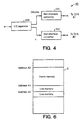
- Figure 4 illustrates digital process 40 in detail.
- digital process 40 consists of a luminance/chrominance separator 400 which separates the luminance (Y) and chrominance (C) information present in the NTSC signal. Chrominace information is passed to non-interlace converter 401 while luminance information is passed to non-interlace converter 402.
- FIG. 5 illustrates luminace/chrominance separator 400 in detail.
- the digital NTSC signal from A/D converter 21 is filtered in band-pass filter 200 and transmitted to temporal filter 406 and vertical filter 408.
- Temporal filter 406 consists of frame delay 202 and subtractor 203. Because the color sub-carrier in the digital NTSC signal is inverted in each adjacent frame when the picture does not have any motion, temporal filter 406 can extract the chrominance signal.
- Vertical filter 408 is a three tap high pass filter. It consists of line delays 204 and 205, mixer 206, and subtractor 207.
- luminance/chrominance separator 400 is a typical two-dimensional luminance/chrominance separator as is common in the art.
- Motion detector 201 of luminance/chrominance separator 400 detects motions in pictures. When the pictures have fewer motions, motion detector 201 connects switch 208 to temporal filter 406. Otherwise, motion detector 201 connects switch 208 to vertical filter 408. The output of switch 208 is the chrominance signal while the output of subtractor 209 is the luminance signal.
- frame delay 202, line delay 204 and line delay 205 are illustrated as independent blocks in Figure 5, those skilled in the art will appreciate that these need not be separate components.
- the output signals from band-pass filter 200 are stored in RAM 5 under the control of traffic controller 4. To allow for the storage, some areas of RAM 5 are assigned to frame memory and others are assigned to line memory. This is illustrated in Figure 6. In this example, the area of RAM 5 between addresses A0 and A1 allows for the storage of frame delay 202. Storage for line delays 204 and 205 are assigned from addresses A1 and A2, respectfully. By utilizing RAM 5 in this manner, digital process 40 does not require a separate memory.
- Figure 7 illustrates non-interlace converters 401 and 402 of digital process 40.
- Blocks 300, 301 and 302 are field delays. In order to interpolate between lines, the current line and the line two fields prior are added in adder 304 and divided by 2. The output is passed to vertical high pass filter 305. The output of delay 300 is passed to vertical low pass filter 306.
- Motion detector 303 detects motions in the pictures and adjusts the ratio of mixing between the outputs of vertical high pass filter 305 and vertical low pass filter 306 in adder 307. When the pictures have fewer motions, the ratio of outputs from filter 305 to those from filter 306 increases. In other cases, the ratio of outputs from filter 306 to those from filter 305 increases.
- the chrominance signal from digital process 40 is converted to an analog signal by D/A converter 41.
- the analog signal output from D/A converter 41 undergoes chroma process 43 which is a conventional analog color signal decoder.
- Chroma process 43 outputs B-Y and R-Y signals to Matrix 45.
- Luminance signal Y from digital process 40 is converted to an analog signal by D/A 42.
- the output analog signal then undergoes luminance process 44, which is a conventional analog luminance signal controller/amplifier.
- luminance process 44 is also provided to Matrix 45.
- Matrix 45 converts the luminance and chrominance inputs described above to RGB signals and provides the RGB signals to mixer 47 though switch 46.
- Mixer 47 mixes the RGB signals from Matrix 45 with any on screen display signals from D/A converter 48 and provides the mixed signal output to CRT 32. All of the above described blocks and processes are under the control of CPU 15 which provides the appropriate control signals.
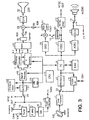
- Figure 3 illustrates a second embodiment of the integrated system.
- the NTSC decoding process for the television circuitry is completely digitized.
- the same numerals are used in Figure 3 as in Figure 2 for similar components.
- chroma process 25, luminance process 26 and Matrix 27 are all fully digitized.
- the mixing operation provided by mixer 29 is a digital mixing process. That is, the digital RGB signal from Matrix 27 is mixed with a digital on screen display signal from OSD block 6 before the mixed signal is finally converted to an analog output in D/A converter 31 for transmission to CRT 32.
- the output of Matrix 27 may be digitally expanded in expander 61 if CRT 32 has a 16x9 aspect ratio. Otherwise, the signal is not expanded.
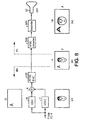
- Figure 8 show the case where the receiver/decoder decodes 16x9 squeezed video which is then displayed in 16x9 format.
- 16x9 video signals are becoming more and more common in the industry.
- OSD data is typically not formatted for display on 16x9 televisions, certain undesirable characteristics result.
- video decoder 7 decodes the 16x9 squeezed picture.
- the video signals are "squeezed” as shown by illustration (ii).
- the on screen display data, in this case the letter A, generated in OSD block 6 is not squeezed, as shown in illustration (i).
- These two signals are mixed in mixer 9 and NTSC encoded in NTSC encoder 100.
- NTSC encoder 100 The output of NTSC encoder 100 is shown in illustration (iii). It includes a squeezed video picture and non-squeezed OSD information. A television NTSC decoder 500 decodes this signal and expander 501 expands the signal to 16x9 size. The result is shown in illustration (iv). Not only is the squeezed video picture expanded (to yield a property formatted image), but the OSD data is also expanded horizontally. This results in the OSD data being distorted on the screen. This is an undesirable characteristic.
- the present television eliminates the problems described above.
- the receive/decoder output is not NTSC encoded.
- the OSD data is mixed with already expanded video data. Therefore, OSD data need never be expanded prior to display, even if the CRT operates in a 16x9 mode. This eliminates the problem presented by existing receiver decoders and it is a further advantage of the present television.
- a fully digitized television may have other functions such as noise reduction, picture-in-picture, etc. Where such functions are implemented, RAM 5 can be used as a shared memory.
Landscapes
- Engineering & Computer Science (AREA)
- Multimedia (AREA)
- Signal Processing (AREA)
- Computer Graphics (AREA)
- Television Systems (AREA)
- Circuits Of Receivers In General (AREA)
Claims (16)
- Télévision comprenant :un premier circuit pour générer un premier signal à partir d'un signal de télévision qui présente un premier format de signal ; etun second circuit qui est couplé audit premier circuit pour générer un second signal à partir d'un signal vidéo numérique qui présente un second format de signal,le second circuit comprenant :un décodeur vidéo pour générer un signal décodé à partir dudit signal vidéo numérique ; etun dispositif de décompression qui est couplé au décodeur vidéo pour laisser passer ou décomprimer ledit signal décodé.
- Télévision selon la revendication 1, dans laquelle ledit premier format de signal est un format NTSC et ledit second format de signal est un format MPEG.
- Télévision selon la revendication 2, dans laquelle ledit premier circuit comprend :un premier processeur pour séparer une information de luminance et de chrominance qui est présente dans ledit signal NTSC ; etun second processeur qui est couplé audit premier processeur pour générer des signaux RGB à partir de l'information de luminance et de chrominance.
- Télévision selon la revendication 3, dans laquelle ledit premier processeur inclut une mémoire qui est partagée par ledit second circuit.
- Télévision selon la revendication 1, dans laquelle ledit second circuit comprend :un bloc d'affichage sur écran pour traiter des données d'affichage sur écran dans ledit signal vidéo numérique ;un mélangeur qui est couplé audit bloc d'affichage sur écran et au dispositif de décompression via un commutateur pour générer un troisième signal, le mélangeur pouvant fonctionner pour mélanger les données d'affichage sur écran traitées et le signal décodé passé ou décomprimé lorsque le commutateur est fermé ; etun convertisseur qui est couplé au mélangeur pour convertir le troisième signal selon le second signal.
- Télévision selon la revendication 3, dans laquelle ledit signal vidéo numérique qui présente ledit format de signal MPEG est crypté avant d'être transmis et ledit second circuit comprend un moyen de décryptage qui est couplé à ladite mémoire pour décrypter ledit signal vidéo numérique crypté.
- Télévision selon la revendication 1, dans laquelle ledit dispositif de compression fonctionne pour décomprimer horizontalement ledit signal décodé lorsque la télévision est dans un premier mode d'affichage et pour laisser passer le signal décodé lorsque la télévision est dans un second mode d'affichage.
- Télévision selon la revendication 5, dans laquelle le bloc d'affichage sur écran fonctionne pour décoder les données d'affichage sur écran, pour construire une information d'affichage sur écran et pour assigner des couleurs à chaque pixel de l'information d'affichage sur écran.
- Télévision selon la revendication 5, dans laquelle ledit mélangeur fonctionne pour laisser passer les données d'affichage sur écran traitées lorsque ledit commutateur est ouvert.
- Télévision selon la revendication 9, dans laquelle le second circuit fonctionne pour émettre en sortie le signal vidéo numérique codé dans ledit premier format de signal sur un enregistreur à cassette vidéo analogique.
- Télévision selon la revendication 5, comprenant un second mélangeur qui est couplé au premier circuit via un second commutateur et au second circuit via un troisième commutateur pour générer un quatrième signal, le second mélangeur fonctionnant pour mélanger le premier signal et le second signal lorsque les second et troisième commutateurs sont fermés.
- Télévision selon la revendication 11, dans laquelle le second mélangeur fonctionne pour faire passer le premier signal sur le quatrième signal lorsque le second commutateur est fermé et que le troisième commutateur est ouvert.
- Télévision selon la revendication 11, dans laquelle le second mélangeur fonctionne pour faire passer le second signal sur le quatrième signal lorsque le second commutateur est ouvert et que le troisième commutateur est fermé.
- Télévision selon la revendication 11, dans laquelle le convertisseur comprend :un convertisseur RGB pour convertir le troisième signal selon un signal RGB ; etun convertisseur numérique-analogique qui est couplé au convertisseur RGB pour convertir le signal RGB selon le second signal.
- Télévision selon la revendication 11, dans laquelle le convertisseur comprend un convertisseur RGB pour convertir le troisième signal selon un signal RGB, le signal RGB étant le second signal.
- Télévision selon la revendication 15, comprenant un convertisseur numérique-analogique qui est couplé au second mélangeur pour convertir le quatrième signal selon un signal d'affichage sur un moniteur d'affichage.
Applications Claiming Priority (3)
| Application Number | Priority Date | Filing Date | Title |
|---|---|---|---|
| US722631 | 1985-04-12 | ||
| US08/722,631 US5844623A (en) | 1996-09-27 | 1996-09-27 | Television with integrated receiver decoder |
| PCT/US1997/017046 WO1998014003A2 (fr) | 1996-09-27 | 1997-09-24 | Television comportant un decodeur recepteur integre |
Publications (2)
| Publication Number | Publication Date |
|---|---|
| EP0928539A2 EP0928539A2 (fr) | 1999-07-14 |
| EP0928539B1 true EP0928539B1 (fr) | 2005-09-07 |
Family
ID=24902686
Family Applications (1)
| Application Number | Title | Priority Date | Filing Date |
|---|---|---|---|
| EP97909867A Expired - Lifetime EP0928539B1 (fr) | 1996-09-27 | 1997-09-24 | Television comportant un decodeur recepteur integre |
Country Status (8)
| Country | Link |
|---|---|
| US (1) | US5844623A (fr) |
| EP (1) | EP0928539B1 (fr) |
| JP (1) | JP2001501400A (fr) |
| KR (1) | KR100488081B1 (fr) |
| AT (1) | ATE304270T1 (fr) |
| AU (1) | AU4737497A (fr) |
| DE (1) | DE69734159T2 (fr) |
| WO (1) | WO1998014003A2 (fr) |
Families Citing this family (30)
| Publication number | Priority date | Publication date | Assignee | Title |
|---|---|---|---|---|
| KR0182922B1 (ko) * | 1996-03-28 | 1999-04-15 | 김광호 | 동기 신호 자기 진단 장치 및 진단 방법 |
| US6313880B1 (en) * | 1997-04-03 | 2001-11-06 | Sony Corporation | Display with one or more display windows and placement dependent cursor and function control |
| US6226047B1 (en) * | 1997-05-30 | 2001-05-01 | Daewoo Electronics Co., Ltd. | Method and apparatus for providing an improved user interface in a settop box |
| JPH1145081A (ja) * | 1997-07-24 | 1999-02-16 | Mitsubishi Electric Corp | オンスクリーンディスプレイ装置および画像表示方法 |
| JP5036098B2 (ja) * | 1997-09-18 | 2012-09-26 | トムソン コンシユーマ エレクトロニクス インコーポレイテツド | ディジタルバスを介して周辺電子装置を制御するディジタルテレビジョン装置 |
| US6118486A (en) * | 1997-09-26 | 2000-09-12 | Sarnoff Corporation | Synchronized multiple format video processing method and apparatus |
| DE69902874T2 (de) * | 1998-01-07 | 2003-01-30 | Thomson Licensing S.A., Boulogne | Vorrichtung zur erzeugung einer verzögerung für videolippensynchronisation und verfahren dafür |
| EP1062626A4 (fr) * | 1998-02-13 | 2004-10-06 | Quvis Inc | Systeme et procede de compression optimisee d'images animees entrelacees |
| US6745390B1 (en) * | 1998-03-12 | 2004-06-01 | United Video Properties, Inc. | Palette management for display of regular graphic objects |
| KR100263896B1 (ko) * | 1998-06-26 | 2000-08-16 | 윤종용 | 디지털/아날로그 방송 신호 처리장치 |
| DE19833309B4 (de) * | 1998-07-24 | 2004-11-25 | Grundig Ag | Fernsehempfänger mit Onscreen-Display |
| KR100559217B1 (ko) * | 1998-12-17 | 2006-06-19 | 비오이 하이디스 테크놀로지 주식회사 | 디스플레이 장치의 공용 입력 회로 |
| JP2001103393A (ja) * | 1999-09-28 | 2001-04-13 | Sony Corp | 受信装置および方法、並びに記録媒体 |
| JP2001119767A (ja) * | 1999-10-19 | 2001-04-27 | Sony Corp | 情報処理装置および方法、情報処理システム並びに記録媒体 |
| US6593973B1 (en) | 2000-03-21 | 2003-07-15 | Gateway, Inc. | Method and apparatus for providing information in video transitions |
| KR100749070B1 (ko) * | 2000-07-14 | 2007-08-13 | 삼성전자주식회사 | 트랜스포트스트림을 역다중화하는 장치 |
| KR100374567B1 (ko) * | 2000-09-29 | 2003-03-04 | 삼성전자주식회사 | 컬러 디스플레이장치를 구비한 휴대용 이동 전화기의 컬러디스플레이 구동장치 |
| EP1286540B1 (fr) * | 2001-08-22 | 2005-06-29 | Thomson Licensing S.A. | Appareils électroniques grand public utilisants une mémoire partagée |
| US7861262B1 (en) * | 2001-09-07 | 2010-12-28 | Enreach Technology, Inc. | Method and system for controlling a personalized video recorder with a set-top box |
| US20030106056A1 (en) * | 2001-11-30 | 2003-06-05 | Naimpally Saiprasad V. | System and method for carriage of program-related information in vertical blanking interval (VBI) of video output signal of program guide-Equipped video equipment |
| ATE336861T1 (de) * | 2002-12-04 | 2006-09-15 | Irdeto Access Bv | Gerät, datenverteilungssystem mit einem solchen geräten, verfahren zur übertragung von daten |
| EP1658722A1 (fr) * | 2003-08-18 | 2006-05-24 | Koninklijke Philips Electronics N.V. | Dispositif d'affichage d'images |
| US7499494B2 (en) * | 2003-12-23 | 2009-03-03 | Genesis Microchip Inc. | Vector selection decision for pixel interpolation |
| US7324163B2 (en) * | 2003-12-23 | 2008-01-29 | Genesis Microchip Inc. | Sub-carrier detection (SCD) for motion threshold logic |
| US7535515B2 (en) * | 2003-12-23 | 2009-05-19 | Ravi Ananthapur Bacche | Motion detection in video signals |
| US7480334B2 (en) * | 2003-12-23 | 2009-01-20 | Genesis Microchip Inc. | Temporal motion vector filtering |
| US7457438B2 (en) | 2003-12-23 | 2008-11-25 | Genesis Microchip Inc. | Robust camera pan vector estimation using iterative center of mass |
| PL367409A1 (en) * | 2004-04-20 | 2005-10-31 | Advanced Digital Broadcast Ltd. | Tv analogue and digital signal receiver and method for receiving analogue and digital signals |
| TWI327860B (en) * | 2006-08-03 | 2010-07-21 | Realtek Semiconductor Corp | Video processing system and related method thereof |
| KR101653627B1 (ko) * | 2015-01-09 | 2016-09-02 | 주식회사 케이티 | 시청 모드 전환 방법, 시스템 및 미디어 재생 장치 |
Family Cites Families (12)
| Publication number | Priority date | Publication date | Assignee | Title |
|---|---|---|---|---|
| JPH0628418B2 (ja) * | 1987-11-19 | 1994-04-13 | シャープ株式会社 | 2方式共用チューナ |
| JPH02237280A (ja) * | 1989-03-10 | 1990-09-19 | Hitachi Ltd | 標準/高品位テレビジョン受信装置 |
| US5208660A (en) * | 1989-07-29 | 1993-05-04 | Sharp Kabushiki Kaisha | Television display apparatus having picture-in-picture display function and the method of operating the same |
| JPH03112279A (ja) * | 1989-09-26 | 1991-05-13 | Toshiba Corp | 高品位多画面テレビジョン受像機 |
| JP2589410B2 (ja) * | 1990-11-29 | 1997-03-12 | シャープ株式会社 | テレビジョン受像機 |
| JPH05292423A (ja) * | 1992-04-10 | 1993-11-05 | Hitachi Ltd | テレビジョン受像機 |
| EP0574901A2 (fr) * | 1992-06-16 | 1993-12-22 | Kabushiki Kaisha Toshiba | Processeur de signaux d'image |
| KR0140674B1 (ko) * | 1993-04-12 | 1998-06-15 | 모리시다 요이치 | 영상신호처리장치 및 처리방법 |
| US5534942A (en) * | 1994-06-17 | 1996-07-09 | Thomson Consumer Electronics, Inc. | On screen display arrangement for digital video signal processing system |
| CA2156871C (fr) * | 1994-09-09 | 2005-04-05 | Thomas Patrick Newberry | Interface unifiee pour guide de programmation |
| JPH0898105A (ja) * | 1994-09-29 | 1996-04-12 | Toshiba Corp | テレビジョン受信機 |
| KR100213048B1 (ko) * | 1995-09-29 | 1999-08-02 | 윤종용 | 아날로그와 디지탈 비디오 모드를 갖는 수신기와 그 수신방법 |
-
1996
- 1996-09-27 US US08/722,631 patent/US5844623A/en not_active Expired - Lifetime
-
1997
- 1997-09-24 AT AT97909867T patent/ATE304270T1/de not_active IP Right Cessation
- 1997-09-24 EP EP97909867A patent/EP0928539B1/fr not_active Expired - Lifetime
- 1997-09-24 WO PCT/US1997/017046 patent/WO1998014003A2/fr not_active Ceased
- 1997-09-24 AU AU47374/97A patent/AU4737497A/en not_active Abandoned
- 1997-09-24 JP JP10515842A patent/JP2001501400A/ja active Pending
- 1997-09-24 DE DE69734159T patent/DE69734159T2/de not_active Expired - Lifetime
- 1997-09-24 KR KR10-1999-7002474A patent/KR100488081B1/ko not_active Expired - Lifetime
Also Published As
| Publication number | Publication date |
|---|---|
| WO1998014003A3 (fr) | 1998-06-11 |
| ATE304270T1 (de) | 2005-09-15 |
| JP2001501400A (ja) | 2001-01-30 |
| HK1021464A1 (en) | 2000-06-09 |
| DE69734159T2 (de) | 2006-06-29 |
| AU4737497A (en) | 1998-04-17 |
| WO1998014003A2 (fr) | 1998-04-02 |
| US5844623A (en) | 1998-12-01 |
| KR20000048557A (ko) | 2000-07-25 |
| EP0928539A2 (fr) | 1999-07-14 |
| KR100488081B1 (ko) | 2005-05-09 |
| DE69734159D1 (de) | 2005-10-13 |
Similar Documents
| Publication | Publication Date | Title |
|---|---|---|
| US5844623A (en) | Television with integrated receiver decoder | |
| US6310654B1 (en) | Decoder device and receiver using the same | |
| KR100265231B1 (ko) | 방송방식이 서로 다른 복수화면의 동시시청 가능한 tv수신장치 | |
| US6490002B1 (en) | Supplemental data path for supporting on-screen displays from external sources in a monitor/TV receiver using a secondary analog signal path | |
| US5512954A (en) | Television receiver with decoder for decoding coded data from a video signal | |
| JP2950503B2 (ja) | Pcモニタ兼用のマルチシステムテレビジョン受像機 | |
| JP2003046898A (ja) | 補助情報処理能力を有するビデオ信号処理システム | |
| HK1021464B (en) | Television with integrated receiver decoder | |
| JP2002125200A (ja) | 動画像フォーマット変換装置 | |
| JP4366391B2 (ja) | 受信装置、表示装置 | |
| JP3884874B2 (ja) | 受信装置 | |
| KR100275697B1 (ko) | 순차주사 방식의 tv에 있어서의 캡션 신호 처리장치 | |
| KR100277951B1 (ko) | 아날로그/디지털 티브이 | |
| KR100238095B1 (ko) | Osd정보로 인한 원화상 가려짐 방지장치 | |
| JP3002031B2 (ja) | 高品位テレビジョン受像機 | |
| JP2006060857A (ja) | 受信機 | |
| JPH05244642A (ja) | Museデコーダ |
Legal Events
| Date | Code | Title | Description |
|---|---|---|---|
| PUAI | Public reference made under article 153(3) epc to a published international application that has entered the european phase |
Free format text: ORIGINAL CODE: 0009012 |
|
| 17P | Request for examination filed |
Effective date: 19990409 |
|
| AK | Designated contracting states |
Kind code of ref document: A2 Designated state(s): AT BE CH DE DK ES FI FR GB GR IE IT LI LU MC NL PT SE |
|
| 17Q | First examination report despatched |
Effective date: 20030718 |
|
| GRAP | Despatch of communication of intention to grant a patent |
Free format text: ORIGINAL CODE: EPIDOSNIGR1 |
|
| RAP1 | Party data changed (applicant data changed or rights of an application transferred) |
Owner name: SONY ELECTRONICS, INC. |
|
| GRAS | Grant fee paid |
Free format text: ORIGINAL CODE: EPIDOSNIGR3 |
|
| GRAA | (expected) grant |
Free format text: ORIGINAL CODE: 0009210 |
|
| AK | Designated contracting states |
Kind code of ref document: B1 Designated state(s): AT BE CH DE DK ES FI FR GB GR IE IT LI LU MC NL PT SE |
|
| PG25 | Lapsed in a contracting state [announced via postgrant information from national office to epo] |
Ref country code: NL Free format text: LAPSE BECAUSE OF FAILURE TO SUBMIT A TRANSLATION OF THE DESCRIPTION OR TO PAY THE FEE WITHIN THE PRESCRIBED TIME-LIMIT Effective date: 20050907 Ref country code: LI Free format text: LAPSE BECAUSE OF FAILURE TO SUBMIT A TRANSLATION OF THE DESCRIPTION OR TO PAY THE FEE WITHIN THE PRESCRIBED TIME-LIMIT Effective date: 20050907 Ref country code: IT Free format text: LAPSE BECAUSE OF FAILURE TO SUBMIT A TRANSLATION OF THE DESCRIPTION OR TO PAY THE FEE WITHIN THE PRESCRIBED TIME-LIMIT;WARNING: LAPSES OF ITALIAN PATENTS WITH EFFECTIVE DATE BEFORE 2007 MAY HAVE OCCURRED AT ANY TIME BEFORE 2007. THE CORRECT EFFECTIVE DATE MAY BE DIFFERENT FROM THE ONE RECORDED. Effective date: 20050907 Ref country code: FI Free format text: LAPSE BECAUSE OF FAILURE TO SUBMIT A TRANSLATION OF THE DESCRIPTION OR TO PAY THE FEE WITHIN THE PRESCRIBED TIME-LIMIT Effective date: 20050907 Ref country code: CH Free format text: LAPSE BECAUSE OF FAILURE TO SUBMIT A TRANSLATION OF THE DESCRIPTION OR TO PAY THE FEE WITHIN THE PRESCRIBED TIME-LIMIT Effective date: 20050907 Ref country code: BE Free format text: LAPSE BECAUSE OF FAILURE TO SUBMIT A TRANSLATION OF THE DESCRIPTION OR TO PAY THE FEE WITHIN THE PRESCRIBED TIME-LIMIT Effective date: 20050907 Ref country code: AT Free format text: LAPSE BECAUSE OF FAILURE TO SUBMIT A TRANSLATION OF THE DESCRIPTION OR TO PAY THE FEE WITHIN THE PRESCRIBED TIME-LIMIT Effective date: 20050907 |
|
| REG | Reference to a national code |
Ref country code: GB Ref legal event code: FG4D |
|
| REG | Reference to a national code |
Ref country code: CH Ref legal event code: EP |
|
| PG25 | Lapsed in a contracting state [announced via postgrant information from national office to epo] |
Ref country code: IE Free format text: LAPSE BECAUSE OF NON-PAYMENT OF DUE FEES Effective date: 20050926 |
|
| PG25 | Lapsed in a contracting state [announced via postgrant information from national office to epo] |
Ref country code: MC Free format text: LAPSE BECAUSE OF NON-PAYMENT OF DUE FEES Effective date: 20050930 |
|
| REG | Reference to a national code |
Ref country code: IE Ref legal event code: FG4D |
|
| REF | Corresponds to: |
Ref document number: 69734159 Country of ref document: DE Date of ref document: 20051013 Kind code of ref document: P |
|
| PG25 | Lapsed in a contracting state [announced via postgrant information from national office to epo] |
Ref country code: LU Free format text: LAPSE BECAUSE OF NON-PAYMENT OF DUE FEES Effective date: 20051107 |
|
| PG25 | Lapsed in a contracting state [announced via postgrant information from national office to epo] |
Ref country code: SE Free format text: LAPSE BECAUSE OF FAILURE TO SUBMIT A TRANSLATION OF THE DESCRIPTION OR TO PAY THE FEE WITHIN THE PRESCRIBED TIME-LIMIT Effective date: 20051207 Ref country code: GR Free format text: LAPSE BECAUSE OF FAILURE TO SUBMIT A TRANSLATION OF THE DESCRIPTION OR TO PAY THE FEE WITHIN THE PRESCRIBED TIME-LIMIT Effective date: 20051207 Ref country code: DK Free format text: LAPSE BECAUSE OF FAILURE TO SUBMIT A TRANSLATION OF THE DESCRIPTION OR TO PAY THE FEE WITHIN THE PRESCRIBED TIME-LIMIT Effective date: 20051207 |
|
| PG25 | Lapsed in a contracting state [announced via postgrant information from national office to epo] |
Ref country code: ES Free format text: LAPSE BECAUSE OF FAILURE TO SUBMIT A TRANSLATION OF THE DESCRIPTION OR TO PAY THE FEE WITHIN THE PRESCRIBED TIME-LIMIT Effective date: 20051218 |
|
| REG | Reference to a national code |
Ref country code: HK Ref legal event code: GR Ref document number: 1021464 Country of ref document: HK |
|
| PG25 | Lapsed in a contracting state [announced via postgrant information from national office to epo] |
Ref country code: PT Free format text: LAPSE BECAUSE OF FAILURE TO SUBMIT A TRANSLATION OF THE DESCRIPTION OR TO PAY THE FEE WITHIN THE PRESCRIBED TIME-LIMIT Effective date: 20060207 |
|
| NLV1 | Nl: lapsed or annulled due to failure to fulfill the requirements of art. 29p and 29m of the patents act | ||
| REG | Reference to a national code |
Ref country code: CH Ref legal event code: PL |
|
| ET | Fr: translation filed | ||
| REG | Reference to a national code |
Ref country code: IE Ref legal event code: MM4A |
|
| PLBE | No opposition filed within time limit |
Free format text: ORIGINAL CODE: 0009261 |
|
| STAA | Information on the status of an ep patent application or granted ep patent |
Free format text: STATUS: NO OPPOSITION FILED WITHIN TIME LIMIT |
|
| 26N | No opposition filed |
Effective date: 20060608 |
|
| REG | Reference to a national code |
Ref country code: FR Ref legal event code: PLFP Year of fee payment: 20 |
|
| PGFP | Annual fee paid to national office [announced via postgrant information from national office to epo] |
Ref country code: GB Payment date: 20160921 Year of fee payment: 20 Ref country code: DE Payment date: 20160920 Year of fee payment: 20 |
|
| PGFP | Annual fee paid to national office [announced via postgrant information from national office to epo] |
Ref country code: FR Payment date: 20160816 Year of fee payment: 20 |
|
| REG | Reference to a national code |
Ref country code: DE Ref legal event code: R071 Ref document number: 69734159 Country of ref document: DE |
|
| REG | Reference to a national code |
Ref country code: GB Ref legal event code: PE20 Expiry date: 20170923 |
|
| PG25 | Lapsed in a contracting state [announced via postgrant information from national office to epo] |
Ref country code: GB Free format text: LAPSE BECAUSE OF EXPIRATION OF PROTECTION Effective date: 20170923 |