EP0928680A1 - Verfahren zur Herstellung von Luftreifen für Fahrzeugräder - Google Patents
Verfahren zur Herstellung von Luftreifen für Fahrzeugräder Download PDFInfo
- Publication number
- EP0928680A1 EP0928680A1 EP97830731A EP97830731A EP0928680A1 EP 0928680 A1 EP0928680 A1 EP 0928680A1 EP 97830731 A EP97830731 A EP 97830731A EP 97830731 A EP97830731 A EP 97830731A EP 0928680 A1 EP0928680 A1 EP 0928680A1
- Authority
- EP
- European Patent Office
- Prior art keywords
- strip
- toroidal support
- lengths
- carcass
- tyre
- Prior art date
- Legal status (The legal status is an assumption and is not a legal conclusion. Google has not performed a legal analysis and makes no representation as to the accuracy of the status listed.)
- Granted
Links
- 238000000034 method Methods 0.000 title claims description 32
- 238000000151 deposition Methods 0.000 claims abstract description 41
- 229920001971 elastomer Polymers 0.000 claims abstract description 40
- 239000000806 elastomer Substances 0.000 claims abstract description 38
- 239000000463 material Substances 0.000 claims abstract description 34
- 230000008021 deposition Effects 0.000 claims description 31
- 238000004519 manufacturing process Methods 0.000 claims description 29
- 230000015572 biosynthetic process Effects 0.000 claims description 25
- 238000000465 moulding Methods 0.000 claims description 22
- 230000009471 action Effects 0.000 claims description 16
- 238000003825 pressing Methods 0.000 claims description 15
- 238000005520 cutting process Methods 0.000 claims description 13
- 238000009826 distribution Methods 0.000 claims description 11
- 238000004073 vulcanization Methods 0.000 claims description 10
- 238000004804 winding Methods 0.000 claims description 9
- 239000011248 coating agent Substances 0.000 claims description 5
- 238000000576 coating method Methods 0.000 claims description 5
- 238000004873 anchoring Methods 0.000 claims description 4
- 238000002360 preparation method Methods 0.000 claims description 4
- 230000007423 decrease Effects 0.000 claims description 3
- 230000007704 transition Effects 0.000 claims description 3
- 239000011324 bead Substances 0.000 description 31
- 230000000875 corresponding effect Effects 0.000 description 13
- 230000000694 effects Effects 0.000 description 11
- 230000008901 benefit Effects 0.000 description 5
- 239000000243 solution Substances 0.000 description 5
- 238000001125 extrusion Methods 0.000 description 4
- 239000002184 metal Substances 0.000 description 4
- 238000005728 strengthening Methods 0.000 description 4
- 238000005452 bending Methods 0.000 description 3
- 238000010276 construction Methods 0.000 description 3
- 230000000284 resting effect Effects 0.000 description 3
- 239000011265 semifinished product Substances 0.000 description 3
- 239000004753 textile Substances 0.000 description 3
- 230000002596 correlated effect Effects 0.000 description 2
- 238000010586 diagram Methods 0.000 description 2
- 239000004744 fabric Substances 0.000 description 2
- 230000006872 improvement Effects 0.000 description 2
- 230000010355 oscillation Effects 0.000 description 2
- 210000000006 pectoral fin Anatomy 0.000 description 2
- 230000008569 process Effects 0.000 description 2
- 239000000047 product Substances 0.000 description 2
- 230000001133 acceleration Effects 0.000 description 1
- 239000000654 additive Substances 0.000 description 1
- 229920005601 base polymer Polymers 0.000 description 1
- 238000003490 calendering Methods 0.000 description 1
- 238000006073 displacement reaction Methods 0.000 description 1
- 230000009977 dual effect Effects 0.000 description 1
- 238000002347 injection Methods 0.000 description 1
- 239000007924 injection Substances 0.000 description 1
- 239000000696 magnetic material Substances 0.000 description 1
- 238000012423 maintenance Methods 0.000 description 1
- 238000007726 management method Methods 0.000 description 1
- 239000007769 metal material Substances 0.000 description 1
- 239000012764 mineral filler Substances 0.000 description 1
- 239000000203 mixture Substances 0.000 description 1
- 230000009467 reduction Effects 0.000 description 1
- 230000003014 reinforcing effect Effects 0.000 description 1
- 238000007493 shaping process Methods 0.000 description 1
- 238000003860 storage Methods 0.000 description 1
- 230000001960 triggered effect Effects 0.000 description 1
Images


Classifications
-
- B—PERFORMING OPERATIONS; TRANSPORTING
- B29—WORKING OF PLASTICS; WORKING OF SUBSTANCES IN A PLASTIC STATE IN GENERAL
- B29D—PRODUCING PARTICULAR ARTICLES FROM PLASTICS OR FROM SUBSTANCES IN A PLASTIC STATE
- B29D30/00—Producing pneumatic or solid tyres or parts thereof
- B29D30/06—Pneumatic tyres or parts thereof (e.g. produced by casting, moulding, compression moulding, injection moulding, centrifugal casting)
- B29D30/08—Building tyres
- B29D30/10—Building tyres on round cores, i.e. the shape of the core is approximately identical with the shape of the completed tyre
- B29D30/16—Applying the layers; Guiding or stretching the layers during application
- B29D30/165—Applying the layers; Guiding or stretching the layers during application by feeding cut-to-length pieces in a direction parallel to the core axis and placing the pieces side-by-side to form an annular element
-
- B—PERFORMING OPERATIONS; TRANSPORTING
- B29—WORKING OF PLASTICS; WORKING OF SUBSTANCES IN A PLASTIC STATE IN GENERAL
- B29D—PRODUCING PARTICULAR ARTICLES FROM PLASTICS OR FROM SUBSTANCES IN A PLASTIC STATE
- B29D30/00—Producing pneumatic or solid tyres or parts thereof
- B29D30/06—Pneumatic tyres or parts thereof (e.g. produced by casting, moulding, compression moulding, injection moulding, centrifugal casting)
- B29D30/48—Bead-rings or bead-cores; Treatment thereof prior to building the tyre
-
- B—PERFORMING OPERATIONS; TRANSPORTING
- B29—WORKING OF PLASTICS; WORKING OF SUBSTANCES IN A PLASTIC STATE IN GENERAL
- B29D—PRODUCING PARTICULAR ARTICLES FROM PLASTICS OR FROM SUBSTANCES IN A PLASTIC STATE
- B29D30/00—Producing pneumatic or solid tyres or parts thereof
- B29D30/06—Pneumatic tyres or parts thereof (e.g. produced by casting, moulding, compression moulding, injection moulding, centrifugal casting)
- B29D30/52—Unvulcanised treads, e.g. on used tyres; Retreading
- B29D30/58—Applying bands of rubber treads, i.e. applying camel backs
- B29D30/62—Applying bands of rubber treads, i.e. applying camel backs by extrusion or injection of the tread on carcass
-
- B—PERFORMING OPERATIONS; TRANSPORTING
- B29—WORKING OF PLASTICS; WORKING OF SUBSTANCES IN A PLASTIC STATE IN GENERAL
- B29D—PRODUCING PARTICULAR ARTICLES FROM PLASTICS OR FROM SUBSTANCES IN A PLASTIC STATE
- B29D30/00—Producing pneumatic or solid tyres or parts thereof
- B29D30/06—Pneumatic tyres or parts thereof (e.g. produced by casting, moulding, compression moulding, injection moulding, centrifugal casting)
- B29D30/08—Building tyres
- B29D30/10—Building tyres on round cores, i.e. the shape of the core is approximately identical with the shape of the completed tyre
- B29D30/16—Applying the layers; Guiding or stretching the layers during application
- B29D2030/1664—Details, accessories or auxiliary operations not provided for in the other subgroups of B29D30/00
- B29D2030/1685—Details, accessories or auxiliary operations not provided for in the other subgroups of B29D30/00 the layers being applied being already cut to the appropriate length, before the application step
Definitions
- the present invention relates to a method of making tyres for vehicle wheels, comprising the steps of: manufacturing a carcass structure; optionally associating a belt structure with the carcass structure at a circumferentially external position thereof; associating a tread band with the belt structure at a circumferentially external position thereof; associating at least one pair of sidewalls with the carcass structure at laterally opposite positions; vulcanizing the obtained tyre.
- tyres for vehicle wheels involves formation of a carcass structure essentially consisting of one or more carcass plies substantially having a toroidal conformation and the axially opposite side edges of which engage respective circumferentially inextensible annular reinforcing elements called "bead cores".
- a belt structure comprising one ore more belt strips in the form of a closed ring, essentially consisting of textile or metal cords suitably oriented relative to each other and to the cords belonging to the adjacent carcass plies.
- a tread band currently consisting of a strip of elastomer material of appropriate thickness is applied to the belt structure, at a circumferentially external position thereof.
- a pair of sidewalls are applied, each of them covering a side portion of the tyre included between a so-called shoulder region, located close to the corresponding side edge of the tread band, and a so-called bead located at the corresponding bead core.
- tyre components are first made separately from each other to be then assembled during a tyre-manufacturing step.
- a rubberized fabric comprising longitudinally-disposed continuous textile or metallic cords, through an extrusion and/or calendering process, is first required.
- This rubberized fabric is submitted to a transverse-cutting operation to produce lengths of predetermined sizes that are subsequently joined together so as to give rise to a continuous ribbon-like semifinished product having transversely-disposed parallel cords.
- this article of manufacture is to be cut into pieces the length of which is correlated with the circumferential extension of the carcass to be made.
- US Patent 5,453,140 herein quoted as an example of the most pertinent state of the art discloses a method and an apparatus forming a carcass ply starting from a single cord previously wound around a reel.
- the cord drawn from the reel by power-driven idler rollers and maintained taut by a pneumatic tensioning system is cut to size to obtain a length of preestablished extension.
- the cord length is picked up by a pick-up element mounted on a belt wound over power-driven pulleys to be extended transversely on the outer surface of a toroidal support.
- the length ends are then engaged by bending members of the belt type operating on the opposite sides of the toroidal support for radially applying the cord length to the toroidal support by means of slide elements acting like fingers along the side portions of the cord length.
- the toroidal support is previously coated with a layer of raw rubber having a dual function, i.e. that of adhering to the cords deposited thereon so as to conveniently hold them in a fixed positioning, and that of constituting an air-proof inner liner in the finished tyre.
- Tyres obtained by this production method have a carcass structure in which the carcass ply or plies consist of individual cords each having two side portions axially spaced apart from each other and oriented radially of the rotation axis of the tyre, and a crown portion extending at a radially outer position between the side portions.
- the invention relates to a method of making a tyre for vehicle wheels, characterized in that manufacturing of the carcass structure involves formation of at least one first carcass ply by the following steps: preparing strip-like lengths each comprising longitudinal and parallel thread-like elements at least partly coated with at least one layer of raw elastomer material; depositing each of the strip-like lengths onto a toroidal support in a substantially U-shaped conformation around the cross section profile of the toroidal support, to define two side portions substantially extending in planes orthogonal to a geometric axis of rotation of the toroidal support at mutually spaced apart positions in an axial direction, and a crown portion extending at a radially outer position between the side portions, wherein the crown portions of each strip-like length are consecutively disposed in side by side relationship along the circumferential extension of the toroidal support, whereas the side portions of each strip-like length are each partly covered with a side portion of at least one circumferentially consecutive length.
- preparation of said strip-like lengths is carried out by cutting actions executed sequentially on at least one continuous strip-like element incorporating said thread-like elements in said layer of raw elastomer material.
- each cutting action is preferably provided to be followed by deposition of the individual length thus obtained onto the toroidal support.
- the side portions belonging to circumferentially contiguous lengths on the toroidal support are caused to mutually converge towards the geometric axis of rotation of the toroidal support itself.
- covering of the side portions of the strip-like lengths progressively decreases starting from a maximum value at radially inner ends of the side portions until a zero value at transition regions between said side portions and crown portions.
- the individual strip-like lengths are sequentially deposited onto the toroidal support according to a circumferential distribution pitch corresponding to the width of the strip-like element.
- the individual strip-like lengths are sequentially deposited onto the toroidal support according to a circumferential distribution pitch corresponding to a multiple of the width of the strip-like element.
- each strip-like length has a width corresponding to a submultiple of the circumferential extension of the toroidal support, as measured at an equatorial plane thereof.
- accomplishment of said at least one first carcass ply further involves a step of sequentially pressing the strip-like element at its side portions, to define regions of increased width close to the inner circumferential edges of the carcass structure.
- Said pressing step can be optionally carried out on the continuous strip-like element before executing the cutting action.
- At least one of the strip-like lengths may be advantageously held on the toroidal support by a suction action produced through the toroidal support.
- each strip-like length involves the steps of: laying down the strip-like length transversely and at a centred position relative to an equatorial plane of the toroidal support; radially moving the strip-like length close to the toroidal support so as to form the crown portion of the length on the toroidal support; translating the opposite ends of the strip-like length substantially radially close to the geometric axis of rotation of the toroidal support for applying the side portions of the strip-like length to the toroidal support; rotating the toroidal support relative to the distributor element through an angular pitch corresponding to the circumferential distribution pitch of the strip-like lengths.
- a step of pressing said side portions of the strip-like lengths against the side walls of the toroidal support may be also provided.
- accomplishment of the carcass structure further comprises the step of applying at least one inextensible annular structure to a region close to each of the inner circumferential edges of the carcass ply obtained from the deposition step.
- accomplishment of the carcass structure further comprises the step of forming a second carcass ply superposed on the first carcass ply and the circumferentially inextensible annular structures.
- Formation of the second carcass ply may advantageously take place in the same manner as accomplishment of the first carcass ply.
- Formation of the carcass ply or plies may be preceded by a step of coating the toroidal support with at least one liner made of an air-proof elastomer material.
- This coating step is advantageously carried out by winding at least one ribbon-like band of an air-proof elastomer material in coils disposed side by side along the cross section profile of the toroidal support.
- the following steps may be provided to be carried out before the vulcanization step: disengaging the tyre from the toroidal support; introducing an air tube into the carcass structure.
- a step of stretching said carcass plies and belt strips may be advantageously carried out for achieving an expansion of the tyre of a linear amount included between 2% and 5%.
- each inextensible annular structure comprises the steps of: depositing at least one first elongated element in concentric coils into a moulding cavity in view of forming a first circumferentially inextensible annular insert substantially in the form of a crown; depositing at least one second elongated element in concentric coils into the moulding cavity in view of forming a second circumferentially inextensible annular insert substantially in the form of a crown coaxially disposed in side by side relationship relative to the first annular insert; forming at least one filling body of raw elastomer material in the moulding cavity, which filling body is interposed between, and intimately joined to the first and second circumferentially inextensible annular anchoring elements.
- Each of the inextensible annular structures made as above described may be conveniently provided to be interposed between the first carcass ply and the second carcass ply.
- Each of said deposition steps of the first and/or second elongated element can be conveniently preceded by a rubberizing step in which said first and/or second elongated element is coated with at least one layer of raw elastomer material.
- Formation of said filling body may advantageously comprise the steps of: interposing at least one annular element of raw elastomer material of a predetermined volume between the first and second inextensible annular inserts; reducing the volume of the moulding cavity in order to compress said annular element of elastomer material between the first and second inextensible annular inserts and deform it until it fills said moulding cavity.
- a tyre for vehicle wheels made by a method according to the present invention has been generally identified by reference numeral 1.
- Tyre 1 essentially comprises a carcass structure 2 having at least one first carcass ply 3 having a substantially toroidal conformation and in engagement, by its opposite circumferential edges, with a pair of inextensible annular structures 4, each of which is located, when the tyre has been completed, at the region usually identified as " tyre bead".
- a belt structure 5 comprising one or more belt strips 6a, 6b and 7.
- a tread band 8 is circumferentially superposed on the belt structure 5 and longitudinal and transverse cuts 8a are formed in said tread band 8, following a moulding operation carried out concurrently with the tyre vulcanization, and such disposed as to define a desired "tread pattern".
- the tyre also comprises a pair of so-called “sidewalls" 9 laterally applied to opposite sides of the carcass structure 2.
- the carcass structure 2 may possibly be coated, on its inner walls, with a liner 10, essentially consisting of a layer of air-proof elastomer material, suitable to ensure the hermetic seal of the inflated tyre.
- the toroidal support 11 has reduced sizes relative to those of the finished tyre, according to a linear amount preferably included between 2% and 5%, measured, just as an indication, along the circumferential extension of the support itself at an equatorial plane X-X thereof which is coincident with the equatorial plane of the tyre.
- the toroidal support 11 which is not described or illustrated in detail in that it is not particularly of importance to the purposes of the invention, may for example consist of a collapsible drum or an inflatable bladder suitably reinforced, so that it may take and maintain the desired toroidal conformation under inflation conditions.
- manufacture of tyre 1 first involves formation of the carcass structure 2 starting with possible formation of the liner 10.
- This liner 10 can be advantageously made by circumferentially winding around the toroidal support 11, at least one ribbon-like band 12 of an air-proof elastomer material, produced from an extruder and/or a calender located close to the toroidal support itself. As viewed from Fig. 1, winding of the ribbon-like band 12 substantially takes place in circumferential coils consecutively disposed in side by side relationship to follow the cross section profile of the outer surface of the toroidal support 11.
- cross section profile it is herein intended a configuration exhibited by the half-section of the toroidal support 11 sectioned along a plane radial to a geometric rotation axis thereof, not shown in the drawings, which is coincident with the geometric axis of rotation of the tyre being manufactured.
- auxiliary annular elements 12a Concurrently with winding of the ribbon-like band 12, application of a pair of auxiliary annular elements 12a can be carried out close to the inner circumferential edges of the carcass structure during its manufacturing step.
- Each of these auxiliary annular elements 12a can be obtained for example by winding the ribbon-like band 12 in a coil axially disposed in side by side relationship with the corresponding coil located at the inner perimetric edge of liner 10 defined or to be defined on the toroidal support 11.
- the auxiliary annular elements 12a can be made up of at least one auxiliary ribbon-like band obtained from a respective extruder located at the toroidal support 11.
- the carcass ply 3 is directly formed on the toroidal support 11 by depositing thereon, as better clarified in the following, a plurality of strip-like lengths 13 obtained from at least one continuous strip-like element 2a preferably having a width included between 3 mm and 20 mm.
- preparation of the continuous strip-like element 2 essentially involves that two or more thread-like elements 14, and preferably three to ten thread-like elements 14, fed from respective reels 14a, should be guided through a first extruder 15 associated with a first extrusion apparatus 16 carrying out feeding of raw elastomer material through the extruder itself.
- extruder it is intended that part of the extrusion apparatus, also identified in this particular field by the term “extrusion head”, provided with a so-called “die” passed through by the product being worked at an outlet port shaped and sized according to the geometrical and dimensional features to be given to the product itself.
- the elastomer material and thread-like elements 14 are intimately joined together within the extruder 15, thereby generating the continuous strip-like element 2a at the outlet thereof, which element is formed of at least one layer of elastomer material 17 in the thickness of which the thread-like elements themselves are incorporated.
- the thread-like elements 14 may each consist for example of a textile cord preferably having a diameter included between 0.6 mm and 1.2 mm, or a metallic cord preferably having a diameter included between 0.3 mm and 2.1 mm.
- the thread-like elements 14 can be disposed in the continuous strip-like element 2a in such a manner that they give the carcass ply 3 thus obtained unexpected qualities of compactness and homogeneity.
- the thread-like elements 14 can be for example disposed according to a density greater than six thread-like elements/centimetre, measured circumferentially on the carcass ply 3 close to the equatorial plane X-X of tyre 1.
- the thread-like elements 14 should be disposed in the strip-like element 2a according to a mutual distance between centres not lower than 1.5 times the diameter of the thread-like elements themselves, in order to enable an appropriate rubberizing operation between the adjacent threads.
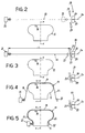
- the continuous strip-like element 2a coming out of extruder 15 can be advantageously guided, optionally through a first accumulator-compensator device 18, on a deposition apparatus 19 diagrammatically shown in Figs. 2 to 5.
- the deposition apparatus 19 essentially comprises first guide members 20, consisting for example of a pair of opposite rollers intended for engagement of the continuous strip-like element 2a produced by the extruder 15, downstream of the accumulator-compensator device 18.
- the strip-like element 2a comes into engagement with a first grip member 21 movable in a direction oriented transversely to the equatorial plane X-X of the toroidal support 11.
- the first grip member 21 is movable between a first operating position in which, as shown in Fig. 2, it engages one end of the continuous strip-like element 2a close to the first guide members consisting of opposite rollers 20, and a second operating position in which, as shown in Fig. 3, it is moved apart from the first guide member in order to lay down the continuous strip-like element 2a transversely of the equatorial plane X-X of the toroidal support 11.
- a second grip member 22 engages the continuous strip-like element 2a close to the first guide members 20.
- a cutting member 23 is applied, to cut the continuous strip-like element 2a at a stretch thereof included between the second grip element 22 and the first guide members 20, giving rise to formation of a strip-like length 13 of a predetermined extension "L".
- the obtained strip-like element 13 is laid down transversely and at a centred position relative to the equatorial plane of the toroidal support.
- the grip members 21 and 22 are simultaneously translated in the direction of the geometric axis of the toroidal support 11 by radially moving the strip-like length 13 close to the toroidal support.
- formation of a crown portion 24 takes place at a centred position on the longitudinal extension of the strip-like length 13, which portion extends at a radially outer position on the toroidal support 11.
- the opposite ends of the strip-like element are definitively applied to the toroidal support 11 so that deposition of length 13 is completed, this length taking a substantially U-shaped configuration around the cross section profile the toroidal support.
- the side portions 25 of the strip-like length can be submitted to a pressing step against the side walls of the toroidal support 11.
- a pair of pressing rollers or equivalent means not shown may be provided for operation on the opposite sides of the toroidal support 11, which rollers are each arranged to act on the respective side portion 25 by a thrust action and simultaneous radial sliding towards the geometric axis of rotation of the toroidal support 11.
- holding of one or more strip-like lengths 13 on the toroidal support 11 can be obtained by carrying out a suction action produced through one or more appropriate holes 26 arranged on the toroidal support.
- the toroidal support 11 can be driven in angular rotation according to a step-by-step movement in synchronism with operation of the deposition apparatus 19, in such a manner that at each cutting action of each strip-like length 13 deposition of the latter onto the toroidal support takes place in a circumferential side by side relationship with the strip-like length 13 previously deposited.
- the angular-rotation pitch of the toroidal support 11 will correspond to the width of said lengths.
- the circumferential distribution pitch of the strip-like lengths 13 may be provided to correspond to a multiple of their width.
- the angular-movement pitch of the toroidal support 11 will correspond to said circumferential distribution pitch.
- the crown portions 24 of each strip-like length 13 are consecutively disposed in side by side relationship along the circumferential extension of the toroidal support 11, whereas each of the side portions 25 of each length 13 is partly superposed with the side portion 25 of at least one length 13 previously laid down, and also partly covered with the side portion 25 of at least one length 13 laid down subsequently.
- the overlapping regions of the strip-like lengths 13 forming the first carcass ply 3 are identified by 13a.
- the side portions 25 in mutual superposition relationship move towards each other substantially in the direction of the geometric axis of rotation of the toroidal support 11, at an angle ⁇ the value of which is correlated with the width "W" of the strip-like elements 13, and in any case with the circumferential distribution pitch thereof, as well as with the value of a maximum radius R to be measured at a point of maximum distance from the geometric axis of rotation of the toroidal support 11.
- thread-like elements 14 belonging to two mutually superposed side portions 25 are disposed in respectively crossed orientations at an angle corresponding to said angle ⁇ , in correlation with the width of the individual lengths 13 and their circumferential distribution pitch as well as with the value of the maximum radius R.
- a pressing step may be provided to be executed on the continuous strip-like element 2a in the regions of its longitudinal extension corresponding to the ends of the strip-like elements 13 to be obtained from said cutting actions. In this manner regions of greater width located at the inner circumferential edges of the formed carcass ply 3 are defined on the extension of each strip-like length 13.
- Said pressing action can be carried out by said guide rollers 20 or by an auxiliary pressing roller (not shown) suitable to press the continuous strip-like element 2a in order to cause pressing of same at the longitudinal-extension sections intended to form the side portions 25 of the individual lengths 13.
- the pressing action causes a reduction in the thickness of the elastomer layer 17 and an increase in the width of the strip-lake element 2a which, as a result, will make the thread-like elements 14 move apart from each other.
- a desired inclination can be given to the crown portions 24 of lengths 13, included by way of example, between 0° and 25° relative to a radial plane passing by the geometrical axis.
- this inclination may be advantageously included between 0° and 3° if tyre 1 is provided with only one carcass ply 3, or between 10° and 20°, and more preferably it may correspond to 15° if, as provided in the embodiment herein illustrated, the carcass structure is comprised of two carcass plies 3, 31.
- Accomplishment of a carcass structure 2 generally comprises the step of applying said inextensible annular structure 4 to an area close to each of the inner circumferential edges of the carcass ply 3 obtained in the previously described manner, for the purpose of creating the carcass regions known as "beads", which are specifically intended for ensuring anchoring of the tyre to a corresponding mounting rim; in accordance with a preferred embodiment of the tyre, the carcass ply thereof is obtained in the above described manner.
- Each of said inextensible annular structures 4 (Fig. 10) comprises a first circumferentially inextensible annular insert 27, substantially in the form of a crown concentric with the geometric axis of rotation of the toroidal support 11 and located close to a corresponding inner circumferential edge of the first carcass ply 3.
- the first annular insert 27 is made of at least one elongated metal element wound up to form several substantially concentric coils 27a. Coils 27a can be defined by a continuous spiral or by concentric rings formed of respective elongated elements.
- a second circumferentially inextensible annular insert 28 substantially extending in the form of a respective crown coaxially disposed in side by side relationship with the first annular insert 27.
- the second annular insert 28 too is preferably made of at least one elongated metal element wound up to form several substantially concentric coils 28a that can be defined by a continuous spiral or by concentric rings formed of respective elongated elements.
- the second annular insert 28 has a radial extension given by the difference between the minimum inner radius and the maximum outer radius of the annular insert, which is greater than the radial extension of the first annular insert 27.
- At least one filling body 29 of elastomer material preferably having a hardness included between 70° and 92° Shore A.
- each annular structure 4 involves formation of a first inextensible annular insert 27 within a moulding cavity 30 defined in a mould 30a, 30b, by deposition of at least one elongated element in concentric coils 27a disposed in mutual side by side relationship according to circumferences of increasingly growing diameter around their geometric winding axis, corresponding to the rotation axis of the tyre.
- This operation can be advantageously carried out through winding of the elongated element in a helical seating arranged in a first cheek 30a of the mould 30a, 30b which can be driven for the purpose in rotation around its own geometric axis.
- a second annular insert 28 is located, formation of which can advantageously take place in the same manner as described for the first annular insert 27.
- the deposition step of the elongated element or elements intended for formation of one or both annular inserts 27, 28 can be advantageously preceded by a rubberizing step during which the elongated element, preferably of metal material, is coated with at least one layer of raw elastomer material that not only ensures an excellent rubber-metal bond on the elongated element itself, but also promotes adhesion thereof for a steady placement in the above mentioned helical seating.
- the first cheek 30a and/or the second cheek 30b may be also advantageously provided to be made of a magnetic material, or to be activated in an electromagnetic manner so as to conveniently attract and retain the respective elongated element, thereby ensuring a steady positioning of coils 27a and/or 28a as they are formed.
- the filling body 29 is formed within the moulding cavity 30.
- Forming of said body may be conveniently carried out by interposing at least one annular element of raw elastomer material of predetermined volume between the first and second annular inserts 27, 28 formed on the respective cheeks 30a, 30b.
- This annular element can have any convenient cross section conformation, provided that its volume corresponds to the inner volume of the moulding chamber 30 when cheeks 30a, 30b are moved close to each other in a closed condition of the mould.
- formation of the filling body 29 can be carried out for example by filling the moulding cavity 30 with elastomer material introduced by injection or any other manner convenient for a person skilled in the art, after moving cheeks 30a, 30b close to each other.
- accomplishment of the carcass structure 2 further involves formation of at least one second carcass ply 31.
- this second carcass ply 31 can be formed directly upon the first carcass ply 3 and the inextensible annular structures 4, so that, as clearly shown in Fig. 10, the second annular insert 28 of each annular structure 4 is disposed in contact with an inner surface of the second carcass ply.
- each annular structure 4 may first involve formation of the first annular insert 27 alone joined to the filling body 29, to carry out application of the second annular insert 28 subsequently to formation of the second carcass ply 31.
- each of the inner circumferential portions of the second carcass ply 31 is interposed between the respective filling body 29 and the second annular insert 28, which is applied to the outer surfaces of the second carcass ply itself, in contact relationship therewith.
- the second carcass ply 31 is manufactured in such a manner that it has its respective thread-like elements 32 disposed according to a crossed orientation relative to the thread-like elements 14 belonging to the first carcass ply 3.
- formation of the second carcass ply 31 conveniently takes place in the same manner as previously described with reference to manufacturing of the first carcass ply 3, i.e. by sequential deposition of respective strip-like lengths 33, to define respective crown portions 34 consecutively disposed in side by side relationship in a circumferential direction and side portions 35 each partly covered by the side portion 35 of the adjacent strip-like length 33.
- the covering or mutual-superposition regions of the strip-like lengths 33 forming the second carcass ply 31 are denoted by 33a.
- the strip-like lengths 33 of the second carcass ply 31 are laid down according to a crossed orientation relative to the strip-like lengths 13 forming the first carcass ply.
- inclination of the strip-like lengths 33 of the second carcass ply 31, with reference to the equatorial plane X-X, should substantially have the same value as the inclination of the strip-like lengths 13 belonging to the first carcass ply 3.
- a belt structure 5 is currently applied to the carcass structure 2.
- This belt structure 5 may be made in any manner convenient for a person skilled in the art and in the embodiment shown it essentially comprises a first and a second belt strips 6a, 6b having cords with a respectively crossed orientation. Superposed on the belt strips is an auxiliary belt strip 7, for instance obtained by winding at least one continuous cord in coils axially disposed in side by side relationship on the first and second belt strips 5, 6.
- tread band 8 and sidewalls 9 which are also obtained in any manner convenient for a person skilled in the art, are applied to the belt structure 5.
- Embodiments of a belt structure, sidewalls and a tread band that can be advantageously put into practice for a complete accomplishment of the tyre in reference on the toroidal support 11 are described in the European Patent Application No. 97830632.2 in the name of the same Applicant.
- Tyre 1 as manufactured and after removal of same from support 11, can be now submitted to a vulcanization step that can be carried out in any known and conventional manner.
- an air tube of closed tubular section may be advantageously associated with tyre 1 in addition to, or in place of liner 10, before the vulcanization step, which air tube is inserted into carcass 2 after the tyre has been removed from the toroidal support 11.
- This air tube not shown in the accompanying drawings, will be inflated after the tyre has been introduced into a vulcanization mould, to supply an inner pressure suitable to ensure a perfect adhesion of the tyre against the mould walls and, in particular, against the mould parts intended for defining the longitudinal and transverse cuts 8a of the tread pattern.
- the carcass plies 3, 31 and belt strips 6a, 6b, 7 are submitted to a stretching step to achieve a pre-tensioning thereof, giving rise to a tyre expansion of a linear amount, measured on the circumferential extension at the equatorial plane X-X of the tyre itself, included by way of example between 2% and 5%.
- This stretching step can be achieved by effect of the inflation pressure of the above mentioned air tube, or other type of inflatable bladder employed in the vulcanization apparatus.
- the present invention achieves important advantages.
- the tyre in reference can be obtained through manufacture of the different components directly on a toroidal support on which the tyre is gradually formed or in any case very close thereto. In this way all problems connected with manufacture, storage and management of semifinished products which are common to manufacturing processes of the traditional type are eliminated.
- simultaneous deposition of a plurality of thread-like elements in accordance with the invention enables the deposition apparatus 19 to be operated at slower rates than required when deposition of individual cords is concerned, which is a further advantage in terms of working accuracy without on the other hand impairing productivity.
- deposition of strip-like lengths directly crownwise to a toroidal support of a profile substantially identical with that of the finished tyre enables densities to be achieved that cannot be reached in the art by known methods providing deposition of a carcass ply in the form of a cylindrical sleeve and subsequent shaping of same into a toroidal form, with consequent thinning of the carcass ply cords disposed crownwise to the finished tyre.
- each strip-like length can be steadily fastened to the toroidal support by a vacuum effect produced through possible suction ducts 26, which steady fastening by vacuum cannot be achieved by known processes carrying out deposition of individual cords.
- the side portions of the strip-like lengths can be disposed at a suitably increased inclination relative to a direction radial to the toroidal support axis, which will enable the expansion undergone by the tyre during the stretching step imposed to it on vulcanization to be efficiently helped.
- the side portions 25, 35 tend to take an orientation in a plane radial to the tyre together with the crown portions 24, 34 extending between the side portions.
- This second strengthening factor is partly by the mutually-crossed arrangement provided for the thread-like elements 14, 32 belonging to the first and second carcass plies 3, 31 respectively, and partly results from the mutually-crossed arrangement provided for the covering or superposition regions 13a, 33a of lengths 13, 33 belonging to the first and second carcass plies.
- construction features of the inextensible annular structures 4 are suitable to further increase the structural strength of the tyre at the bead and sidewall regions.
- the presence of the circumferentially inextensible annular inserts 27, 28 intimately joined to the carcass plies 3, 31 creates a further "bond" between the mutually-crossed thread-like elements 14, 32 belonging to the first and second carcass plies 3, 31.
- the carcass structure 2 is further strengthened at the regions coresponding to the tyre beads without requiring for the purpose employment of additional strip-like inserts, usually called “flippers", wound like a slipknot around the inextensible annular structures 4, said flippers being used on the contrary in the known art.
- Fig. 12 shows a tyre 101 of the traditional type, mounted on a respective rim 100 that, at each tyre bead, has a bead seat 100a axially delimited by a flange 100b defining an outer side edge of the rim and a security hump 100c.
- the different components of tyre 101 are marked by numeric indices obtained by adding 100 to the numeric value of the indices previously employed for corresponding parts of tyre 1 in accordance with the invention.
- the carcass ply or plies tend to bend at the tyre sidewall under the effect of the slip thrust T, generated parallelly to the rotation axis of the tyre by friction of the tread band 108 on the ground, during a bend.
- This slip thrust T transmitted along the ply or plies 103 of the carcass structure 102 up to the inextensible annular structures 104, generates a radial component Tr and an axial component Ts.
- the radial component Tr is counteracted by the circumferential inextensibility of the annular structure 104 resting, over the whole circumferential volume thereof, on the respective seat 100a provided in rim 100.
- the axial component Ts oriented towards the equatorial plane of the tyre, tends to move the tyre bead away from the flange 100b of rim 100 and is usually counteracted by the security hump 100c.
- the radial sizes of the security hump are however rather limited and it may easily happen that, when the axial component Ts exceeds given values, the tyre bead is removed from its respective seat 100a, instantaneously causing a full deflation and a consequent loss of functionality of tyre 100. This phenomenon is also facilitated by the fact that the tyre bead structured in accordance with the known art, under the effect of the slip thrust T, tends to "roll" on the security hump 100c.
- the annular structures 4 of the invention interposed between the first and second carcass plies 3, 31, prevent the tyre beads from rotating, under the effect of the slip thrust T, around their resting point against the respective security humps 100c provided in rim 100.
- the slip force T is equably shared between the first and second carcass plies and transmitted along said plies until the respective first and second inextensible annular elements 27, 28 provided in structure 4.
- the slip force T portion transmitted along the second carcass ply 31 generates a radial component Tr 2 as well, which is counteracted by the circumferential inextensibility of the second annular insert 28, and an axial component tending to push the bead against the flange 100b but which has a practically zero value when, as in the case shown, the inner circumferential edge of the second carcass ply takes an orientation perpendicular to the axis of the tyre 1.
- a correct positioning of the bead is in any case ensured by the above described axial component Ts 1 .
- the tyre having beads made in accordance with the present invention can bear the so-called "J-curve Test" without removal of the bead from its seat until inflation pressures of 0.5 bar, whereas in the known art tyres that are unable to counteract bead displacements from their seats at pressures lower than 0.8-1.0 bar are considered as acceptable.
- annular inserts 27 and 28 furnish a further structural protection of the tyre at the beads.
Landscapes
- Engineering & Computer Science (AREA)
- Mechanical Engineering (AREA)
- Tyre Moulding (AREA)
- Tires In General (AREA)
- Heating, Cooling, Or Curing Plastics Or The Like In General (AREA)
Priority Applications (15)
| Application Number | Priority Date | Filing Date | Title |
|---|---|---|---|
| EP97830731A EP0928680B1 (de) | 1997-12-30 | 1997-12-30 | Verfahren zur Herstellung von Luftreifen für Fahrzeugräder |
| AT97830731T ATE234194T1 (de) | 1997-12-30 | 1997-12-30 | Verfahren zur herstellung von luftreifen für fahrzeugräder |
| DE69719771T DE69719771T2 (de) | 1997-12-30 | 1997-12-30 | Verfahren zur Herstellung von Luftreifen für Fahrzeugräder |
| ES97830731T ES2195109T3 (es) | 1997-12-30 | 1997-12-30 | Procedimiento para la fabricacion de neumaticos para ruedas de vehiculos. |
| PT97830731T PT928680E (pt) | 1997-12-30 | 1997-12-30 | Metodo para fabricar pneus para rodas de veiculo |
| TW087121667A TW407107B (en) | 1997-12-30 | 1998-12-24 | A method for making tyres for vehicle wheels |
| JP36883198A JP4651758B2 (ja) | 1997-12-30 | 1998-12-25 | タイヤの製造方法 |
| RU98123825/12A RU2213009C2 (ru) | 1997-12-30 | 1998-12-29 | Способ изготовления шин для колес транспортного средства |
| BRPI9805745-6A BR9805745B1 (pt) | 1997-12-30 | 1998-12-29 | processo de construÇço de um pneu. |
| CNB981262147A CN1229217C (zh) | 1997-12-30 | 1998-12-29 | 车轮轮胎的制造方法 |
| ARP980106743A AR014218A1 (es) | 1997-12-30 | 1998-12-30 | Un metodo para fabricar neumaticos para ruedas de vehiculos |
| KR1019980061778A KR100556690B1 (ko) | 1997-12-30 | 1998-12-30 | 차량바퀴용타이어의제조방법 |
| TR1998/02757A TR199802757A1 (xx) | 1997-12-30 | 1998-12-30 | Ta��t tekerlekleri i�in bir lastik yap�m y�ntemi. |
| US09/840,095 US7041185B2 (en) | 1997-12-30 | 2001-04-24 | Method of making a tire |
| US11/387,697 US7909953B2 (en) | 1997-12-30 | 2006-03-24 | Method for making tires for vehicle wheels |
Applications Claiming Priority (1)
| Application Number | Priority Date | Filing Date | Title |
|---|---|---|---|
| EP97830731A EP0928680B1 (de) | 1997-12-30 | 1997-12-30 | Verfahren zur Herstellung von Luftreifen für Fahrzeugräder |
Publications (2)
| Publication Number | Publication Date |
|---|---|
| EP0928680A1 true EP0928680A1 (de) | 1999-07-14 |
| EP0928680B1 EP0928680B1 (de) | 2003-03-12 |
Family
ID=8230933
Family Applications (1)
| Application Number | Title | Priority Date | Filing Date |
|---|---|---|---|
| EP97830731A Expired - Lifetime EP0928680B1 (de) | 1997-12-30 | 1997-12-30 | Verfahren zur Herstellung von Luftreifen für Fahrzeugräder |
Country Status (14)
| Country | Link |
|---|---|
| US (2) | US7041185B2 (de) |
| EP (1) | EP0928680B1 (de) |
| JP (1) | JP4651758B2 (de) |
| KR (1) | KR100556690B1 (de) |
| CN (1) | CN1229217C (de) |
| AR (1) | AR014218A1 (de) |
| AT (1) | ATE234194T1 (de) |
| BR (1) | BR9805745B1 (de) |
| DE (1) | DE69719771T2 (de) |
| ES (1) | ES2195109T3 (de) |
| PT (1) | PT928680E (de) |
| RU (1) | RU2213009C2 (de) |
| TR (1) | TR199802757A1 (de) |
| TW (1) | TW407107B (de) |
Cited By (57)
| Publication number | Priority date | Publication date | Assignee | Title |
|---|---|---|---|---|
| EP0956940A4 (de) * | 1997-10-03 | 2000-12-06 | Bridgestone Corp | Verfahren und gerät zum formen einer reifenverstärkungslage |
| EP1057664A1 (de) | 1999-06-02 | 2000-12-06 | PIRELLI PNEUMATICI S.p.A. | Vorrichtung zur Prüfung des Luftdrucks in Reifen eines Kraftfahrzeugs |
| EP1243404A1 (de) * | 2001-03-20 | 2002-09-25 | Karl Eugen Fischer GmbH Maschinenfabrik | Vorschubeinrichtung, insbesondere für Cordbänder |
| WO2003051619A1 (en) * | 2001-12-19 | 2003-06-26 | Pirelli Pneumatici S.P.A. | Elastomeric semifinished product for the production of a tyre liner, and tyre provided with said liner |
| US6669457B2 (en) | 2000-02-21 | 2003-12-30 | Pirelli Pneumatici S.P.A. | Dismountable toroidal support for tire manufacture |
| WO2004002758A1 (en) | 2002-06-28 | 2004-01-08 | Pirelli Pneumatici S.P.A. | System for monitoring characteristic parameters of a tyre |
| WO2004002759A1 (en) | 2002-06-28 | 2004-01-08 | Pirelli Pneumatici S.P.A. | System and monitoring characteristic parameters of a tyre |
| WO2004045837A1 (en) * | 2002-11-20 | 2004-06-03 | Pirelli Pneumatici, S.P.A. | Method and apparatus for molding and curing a tyre for vehicle wheels |
| US6789590B2 (en) | 1998-06-05 | 2004-09-14 | Pirelli Pneumatici S.P.A. | Method of manufacturing a tire including carcass ply terminal zones engaged with respective annular reinforcing structures, the tire, and wheel including the tire |
| US6814119B2 (en) | 2000-03-31 | 2004-11-09 | Pirelli Pneumatici S.P.A. | Self-supporting tire for a vehicle wheel and method for manufacturing the tire |
| US6829926B2 (en) | 1999-06-02 | 2004-12-14 | Pirelli Pneumatici S.P.A. | System for checking the air pressure in the tires of a motor vehicle |
| US6899154B2 (en) | 2000-01-28 | 2005-05-31 | Pirelli Pneumatici S.P.A. | Carcass structure for a tire and tire provided with the carcass structure |
| WO2005058588A1 (en) * | 2003-12-12 | 2005-06-30 | Pirelli Pneumatici S.P.A. | Process for manufacturing a tyre comprising the step of marking a structural element thereof |
| US6945295B2 (en) | 2000-01-28 | 2005-09-20 | Pirelli Pneumatici S.P.A. | Tire for a vehicle wheel comprising a particular carcass structure |
| WO2006070412A1 (en) | 2004-12-28 | 2006-07-06 | Pirelli Tyre S.P.A. | Method and apparatus for manufacturing pneumatic tyres |
| US7094302B2 (en) | 2001-03-29 | 2006-08-22 | Pirelli Pneumatici S.P.A. | Method of forming a belt structure in a tire, in particular for motorcycle wheels |
| US7096908B2 (en) | 2001-09-28 | 2006-08-29 | Pirelli Pneumatici S.P.A. | Self-supporting tyre for a vehicle wheel, and method of making the tyre |
| US7144465B2 (en) | 2001-02-23 | 2006-12-05 | Pirelli Pneumatici S.P.A. | Crosslinkable elastomeric composition, tire including a crosslinked elastomeric material, and process for producing the tire |
| US7150301B2 (en) | 2000-05-30 | 2006-12-19 | Pirelli Pneumatici S.P.A. | Motor vehicle tire with low rolling resistance |
| US7152642B2 (en) | 2000-09-26 | 2006-12-26 | Pirelli Pneumatici S.P.A. | Tire for a vehicle wheel and process for producing the tire |
| US7238248B2 (en) | 2001-05-30 | 2007-07-03 | Pirelli Pneumatici S.P.A. | Method of building a tyre and tyre for a two-wheeled vehicle |
| WO2008071220A1 (en) * | 2006-12-15 | 2008-06-19 | Pirelli Tyre S.P.A. | Process for producing and storing a semi-finished product made of elastomeric material |
| US7412879B2 (en) | 2003-09-19 | 2008-08-19 | Pirelli Pneumatici S.P.A. | Method for monitoring tyre deformations and monitoring system therefor |
| US7431063B2 (en) | 2001-11-27 | 2008-10-07 | Pirelli Pneumatici S.P.A. | Method for producing a belt structure for a vehicle tyre and vehicle tyre including the belt structure |
| US7479196B2 (en) | 2002-02-19 | 2009-01-20 | Pirelli Pneumatici S.P.A. | Method for manufacturing or retreading a pneumatic tire |
| US7485201B2 (en) | 2001-12-21 | 2009-02-03 | Pirelli Pneumatici S.P.A. | Automatic plant and method for producing tires |
| CN100467287C (zh) * | 2003-06-24 | 2009-03-11 | 倍耐力轮胎公司 | 带有胎冠和基部结构胎面胶的车轮用轮胎 |
| WO2009068939A1 (en) | 2007-11-30 | 2009-06-04 | Pirelli Tyre S.P.A. | Process and apparatus for manufacturing tyres for vehicle wheels |
| US7556076B2 (en) | 2000-07-31 | 2009-07-07 | Michelin Recherche Et Technique S.A. | Tire for two-wheeled vehicle comprising an anti-vibration means |
| RU2362679C2 (ru) * | 2004-05-10 | 2009-07-27 | Пирелли Тайр С.П.А. | Способ изготовления шины |
| WO2009143895A1 (en) * | 2008-05-30 | 2009-12-03 | Pirelli Tyre S.P.A. | Tyre comprising a sealing material comprising a partially cross-linked styrene-butadiene rubber |
| US7691217B2 (en) | 2002-05-31 | 2010-04-06 | Pirelli Pneumatici S.P.A. | Process for manufacturing a tyre and toroidal support for carrying out the process |
| WO2010097671A1 (en) | 2009-02-24 | 2010-09-02 | Pirelli Tyre S.P.A. | Process for manufacturing tyres for vehicle wheels |
| WO2010122396A2 (en) | 2009-04-22 | 2010-10-28 | Pirelli Tyre S.P.A. | Tyre for heavy load vehicle wheels |
| WO2010124977A1 (en) | 2009-04-29 | 2010-11-04 | Pirelli Tyre S.P.A. | Tire with controlled resistance to the formation of surface defects |
| US7934528B2 (en) | 2001-12-21 | 2011-05-03 | Pirelli Pneumatici S.P.A. | Elastomeric composition including at least one salt or oxide of a transition metal and tyre and tread band including the composition |
| US7964128B2 (en) | 2001-12-19 | 2011-06-21 | Pirelli Pneumatici S.P.A. | Process and apparatus for continuously producing an elastomeric composition |
| WO2011073834A1 (en) * | 2009-12-14 | 2011-06-23 | Pirelli Tyre S.P.A. | Process for building tyres for vehicle wheels and tyre for vehicle wheels |
| US20110146888A1 (en) * | 2009-12-23 | 2011-06-23 | D Sidocky Richard Michael | Method for forming stratified rubber article with variable cure rate |
| WO2011077330A1 (en) | 2009-12-22 | 2011-06-30 | Pirelli Tyre S.P.A. | Extrusion process and device for producing elastomeric compounds |
| US8007710B2 (en) | 2004-12-28 | 2011-08-30 | Pirelli Tyre S.P.A. | Method and apparatus for manufacturing pneumatic tyres |
| US8082964B2 (en) | 2003-04-18 | 2011-12-27 | Pirelli Pneumatici S.P.A. | Tyre for a vehicle wheel and method of manufacturing the tyre |
| US8236215B2 (en) | 2002-07-11 | 2012-08-07 | Pirelli Pneumatici S.P.A. | Process and apparatus for continuously producing an elastomeric composition |
| US8240350B2 (en) | 2005-04-28 | 2012-08-14 | Pirelli Tyre S.P.A. | Tire and crosslinkable elastomeric composition |
| US8342220B2 (en) | 2006-07-28 | 2013-01-01 | Pirelli Tyre S.P.A. | Process and apparatus for manufacturing a reinforcing structure for tyres of vehicles |
| US8460590B2 (en) | 2001-07-25 | 2013-06-11 | Pirelli Pneumatici S.P.A. | Process for continuously producing an elastomeric composition |
| US8499806B2 (en) | 2005-12-20 | 2013-08-06 | Pirelli Tyre S.P.A. | Pneumatic tire having an asymmetric tread profile |
| US8512495B2 (en) | 2008-12-11 | 2013-08-20 | Pirelli Tyre S.P.A. | Process and appartus for manufacturing tyres for vehicle wheels |
| US8770245B2 (en) | 2008-12-22 | 2014-07-08 | Pirelli Tyre S.P.A. | Tyre for two-wheeled vehicle and process for manufacturing the same |
| US20140261953A1 (en) * | 2013-03-15 | 2014-09-18 | Bridgestone Americas Tire Operations, Llc | Pneumatic tire and method of manufacture |
| US9017500B2 (en) | 2008-12-22 | 2015-04-28 | Pirelli Tyre S.P.A. | Tyre for two-wheeled vehicle and process for manufacturing the same |
| US9314982B2 (en) | 2006-07-28 | 2016-04-19 | Pirelli Tyre S.P.A. | Process and apparatus for manufacturing a reinforcing structure for tyres of vehicles |
| US9346320B2 (en) | 2003-06-19 | 2016-05-24 | Pirelli Pneumatici S.P.A. | Tyre with specified belt structure |
| US9403309B2 (en) | 2010-06-28 | 2016-08-02 | Pirelli Tyre S.P.A. | Method for controlling the heating of an extrusion device of a semi-finished product made of elastomeric material |
| US9744733B2 (en) | 2009-04-08 | 2017-08-29 | Pirelli Tyre S.P.A. | Process for manufacturing tyres for vehicle wheels |
| EP1201414B2 (de) † | 2000-10-30 | 2019-12-04 | Sumitomo Rubber Industries, Ltd. | Verfahren zum Herstellen der Seitenwände von Fahrzeugreifen |
| US10668679B2 (en) | 2014-12-29 | 2020-06-02 | Pirelli Tyre S.P.A. | Process for producing tyres |
Families Citing this family (42)
| Publication number | Priority date | Publication date | Assignee | Title |
|---|---|---|---|---|
| US6318432B1 (en) * | 1997-11-28 | 2001-11-20 | Pirelli Pneumatici S.P.A. | Tire for vehicle wheels |
| EP0943421B1 (de) * | 1997-11-28 | 2003-05-28 | Pirelli Pneumatici Societa' Per Azioni | Verfahren zur Herstellung von Luftreifen für Fahrzeugräder |
| DE69719771T2 (de) * | 1997-12-30 | 2003-12-11 | Pirelli Pneumatici S.P.A., Milano | Verfahren zur Herstellung von Luftreifen für Fahrzeugräder |
| US6328084B1 (en) | 1997-12-30 | 2001-12-11 | Pirelli Pneumatici S.P.A. | Vehicle tire with a particular carcass ply and/or a particular circumferentially inextensible annular structure |
| US6763868B1 (en) | 1998-07-31 | 2004-07-20 | Pirelli Pneumatici S.P.A. | Tire for a two-wheeled vehicle and carcass structure for the tire |
| US6941992B2 (en) | 1998-10-30 | 2005-09-13 | Pirelli Pneumatici S.P.A. | Tire for a vehicle wheel and method of manufacturing the tire |
| KR100718257B1 (ko) * | 1998-10-30 | 2007-05-16 | 피렐리 타이어 소시에떼 퍼 아찌오니 | 차량 타이어용 카커스 구조체의 제조방법 및 상기 방법에 의해 얻어지는 카커스 구조체 |
| TR200101839T2 (tr) * | 1998-12-23 | 2001-12-21 | Pirelli Pneumatici S.P.A. | Lastikler için bir karkasın imalat yöntemi ve bu yöntemle elde edilen bir karkas. |
| ATE267082T1 (de) * | 1999-11-26 | 2004-06-15 | Pirelli | Verfahren und vorrichtung zur herstellung einer verstärkungsstruktur für fahrzeugluftreifen |
| ES2230279T3 (es) * | 2000-01-28 | 2005-05-01 | Pirelli Pneumatici Societa Per Azioni | Estructura de carcasa para neumaticos y neumatico provisto de dicha estructura de carcasa. |
| ES2248306T3 (es) * | 2000-01-28 | 2006-03-16 | Pirelli Pneumatici S.P.A. | Estructura de carcasa para neumaticos para ruedas de vehiculos y neumaticos que comprenden dicha estructura de carcasa. |
| US20090107610A1 (en) * | 2000-01-28 | 2009-04-30 | Renato Caretta | Tyre for vehicle wheel comprising a particular carcass structure |
| DE60117695T2 (de) | 2000-12-22 | 2006-11-09 | Pirelli Pneumatici S.P.A. | Selbststützender reifen für fahrzeugsräder und verfahren zur herstellung desselben |
| JP2005503954A (ja) | 2001-09-27 | 2005-02-10 | ピレリ・プネウマティチ・ソチエタ・ペル・アツィオーニ | 自己シールタイヤ、およびその製造方法 |
| DE60141986D1 (de) | 2001-10-30 | 2010-06-10 | Pirelli | Reifen mit einem wulstkern mit vorgeformten drähten |
| JP4274945B2 (ja) | 2002-02-05 | 2009-06-10 | ピレリ・タイヤ・ソチエタ・ペル・アツィオーニ | タイヤの製造方法、およびタイヤの製造に使用する押出機 |
| BR0211505A (pt) | 2002-05-31 | 2004-09-14 | Pirelli | Pneu para rodas de veìculo e processo para produzir o mesmo |
| JP4205055B2 (ja) * | 2002-06-18 | 2009-01-07 | 株式会社ブリヂストン | タイヤ構成部材の貼着装置および貼着方法 |
| JP2005530652A (ja) * | 2002-06-27 | 2005-10-13 | ピレリ・プネウマティチ・ソチエタ・ペル・アツィオーニ | 補強ビード構造を有する車輪用タイヤ |
| US20040154727A1 (en) * | 2003-02-11 | 2004-08-12 | Weissert James Thomas | Method and apparatus for manufacturing carcass plies for a tire |
| WO2005053942A1 (en) | 2003-11-28 | 2005-06-16 | Pirelli Pneumatici S.P.A. | Process for manufacturing a tyre and toroidal support for carrying out said process |
| AU2003296841A1 (en) | 2003-12-29 | 2005-08-12 | Pirelli Pneumatici S.P.A. | Method for manufacturing a tyre |
| US20050224158A1 (en) * | 2004-04-01 | 2005-10-13 | Dyrlund Christopher D | Bead construction method and apparatus for a tire |
| DE602004022598D1 (de) * | 2004-09-20 | 2009-09-24 | Pirelli | Verfahren und anlage zur herstellung von reifen |
| BRPI0419038B1 (pt) * | 2004-09-20 | 2014-04-08 | Pirelli | Aparelho e método para fabricar pneus |
| JP4695429B2 (ja) * | 2004-11-11 | 2011-06-08 | 住友ゴム工業株式会社 | 空気入りタイヤ及びその製造方法 |
| JP4540452B2 (ja) | 2004-11-19 | 2010-09-08 | 株式会社ブリヂストン | 空気入りタイヤの製造装置及び製造方法 |
| WO2006114117A1 (en) | 2005-04-27 | 2006-11-02 | Pirelli Tyre S.P.A. | Method for extruding a polymeric material and extrusion head therefor |
| JP2006347363A (ja) * | 2005-06-16 | 2006-12-28 | Bridgestone Corp | 空気入りタイヤ並びにその製造装置及び製造方法 |
| CA2634069A1 (en) | 2005-12-23 | 2007-07-05 | Pirelli Tyre S.P.A. | Pneumatic tire having an improved belt structure |
| US8299152B2 (en) | 2006-10-30 | 2012-10-30 | Pirelli Tyre S.P.A. | Tire for vehicle wheels comprising crosslinked elastomeric composition |
| FR2917007B1 (fr) * | 2007-06-06 | 2011-02-11 | Soc Technologie Michelin Stm | Procede et dispositif pour la fabrication d'une ebauche de pneumatique. |
| EP2155481B1 (de) | 2007-06-11 | 2012-04-18 | Pirelli Tyre S.P.A. | Verfahren und Vorrichtung zur Herstellung von Reifen |
| US20080314524A1 (en) * | 2007-06-20 | 2008-12-25 | Andres Ignacio Delgado | Method for single line tire ply construction |
| CN101855053B (zh) * | 2007-11-15 | 2014-06-04 | 倍耐力轮胎股份公司 | 用于制造轮胎的方法和设备 |
| RU2389923C1 (ru) * | 2008-08-27 | 2010-05-20 | Государственное научное учреждение "Институт механики металлополимерных систем имени В.А. Белого Национальной академии наук Беларуси" | Клиновидный ремень |
| JP5216067B2 (ja) * | 2010-10-22 | 2013-06-19 | 住友ゴム工業株式会社 | 空気入りタイヤの製造方法 |
| ITMI20112039A1 (it) * | 2011-11-10 | 2013-05-11 | Pirelli | Processo ed impianto per realizzare pneumatici differenti tra loro |
| ITMI20112269A1 (it) * | 2011-12-15 | 2013-06-16 | Pirelli | Metodo per controllare la deposizione di uno strato di materiale polimerico sigillante su un tamburo di formatura e processo per produrre pneumatici auto-sigillanti per ruote di veicoli |
| CN110435360A (zh) * | 2013-03-06 | 2019-11-12 | 倍耐力轮胎股份公司 | 用于车辆车轮的轮胎 |
| MX2018015923A (es) * | 2016-07-22 | 2019-03-28 | Pirelli | Metodo y aparato para la construccion de neumaticos para ruedas de vehiculos. |
| FR3116227B1 (fr) * | 2020-11-18 | 2022-10-14 | Michelin & Cie | Procédé de fabrication d’ébauches de pneumatique |
Citations (13)
| Publication number | Priority date | Publication date | Assignee | Title |
|---|---|---|---|---|
| FR384231A (fr) * | 1907-11-22 | 1908-04-01 | Henriette Levieuze | Enveloppe pour bandages pneumatiques |
| US1350995A (en) * | 1916-10-10 | 1920-08-24 | Charles Schwartz A | Vehicle-tire |
| US1728957A (en) * | 1923-03-16 | 1929-09-24 | Dickinson Cord Tire Corp | Cord-tire-making machine |
| FR1317045A (fr) * | 1961-03-08 | 1963-02-01 | Dunlop Rubber Co | Procédé et appareil pour la fabrication de bandages pneumatiques de grandes dimensions |
| US4144006A (en) * | 1977-02-21 | 1979-03-13 | Sumitomo Rubber Industries, Ltd. | Metal mold for vulcanization of tires |
| US4168193A (en) * | 1976-06-23 | 1979-09-18 | The Firestone Tire & Rubber Company | Method of manufacturing rubber articles and means for carrying out said method |
| US4248287A (en) * | 1977-11-08 | 1981-02-03 | Brad Ragan, Inc. | Method of and apparatus for making flotation tire and tire product |
| JPS60157840A (ja) * | 1984-01-27 | 1985-08-19 | Sumitomo Rubber Ind Ltd | ビ−ドフイラ−の成形方法 |
| JPH01306233A (ja) * | 1988-06-03 | 1989-12-11 | Toyo Tire & Rubber Co Ltd | 空気入りタイヤの製造方法 |
| US5171394A (en) * | 1986-09-17 | 1992-12-15 | Compagnie Generale Des Etablissements Michelin | Method and apparatus of manufacturing a tire by the laying of rubber products onto a firm support |
| EP0557615A1 (de) * | 1992-01-23 | 1993-09-01 | Bridgestone Corporation | Verfahren und Vorrichtung zur Herstellung von verstärkten Elastomerstreifen |
| EP0664232A1 (de) * | 1994-01-21 | 1995-07-26 | Sedepro | Verankerung von der Karkasse eines Reifens |
| EP0780221A2 (de) * | 1995-12-21 | 1997-06-25 | Bridgestone Corporation | Verfahren und Vorrichtung zur Herstellung eines verstärkten Elastomerstreifens |
Family Cites Families (22)
| Publication number | Priority date | Publication date | Assignee | Title |
|---|---|---|---|---|
| US948064A (en) | 1909-05-07 | 1910-02-01 | Frank A Seiberling | Process of making tire-shoes. |
| GB890502A (en) | 1957-07-10 | 1962-02-28 | Dunlop Rubber Co | Improvements in or relating to pneumatic tyre covers |
| GB922395A (en) | 1958-09-05 | 1963-04-03 | Dunlop Rubber Co | Improvements in or relating to pneumatic tyres |
| GB940792A (en) * | 1959-05-08 | 1963-11-06 | Dunlop Rubber Co | Improvements in and relating to pneumatic tyres |
| US3240250A (en) * | 1964-06-11 | 1966-03-15 | Nat Standard Co | Pneumatic tires |
| US3431962A (en) * | 1966-08-22 | 1969-03-11 | Goodyear Tire & Rubber | Reinforcement for pneumatic tires and the like |
| US3826297A (en) * | 1972-10-26 | 1974-07-30 | Steelastic Co | Radial tire carcass |
| US3999585A (en) * | 1975-04-28 | 1976-12-28 | Caterpillar Tractor Co. | Pneumatic tire having breaker structure |
| US4637014A (en) * | 1984-02-17 | 1987-01-13 | Burroughs Corporation | Method of inserting and removing isochronous data into a sequence of nonisochronous data characters without slot allocation on a computer network |
| US4673014A (en) * | 1985-06-06 | 1987-06-16 | Grumman Aerospace Corporation | Run-flat tire incorporating tape-wrapped helical coil band and method of forming |
| US4830781A (en) * | 1987-09-18 | 1989-05-16 | The Armstrong Rubber Company | Tire body reinforcing component and apparatus and method for producing same |
| GB8726628D0 (en) | 1987-11-13 | 1987-12-16 | Holroyd Associates Ltd | Bead filler construction |
| FR2677577A1 (fr) | 1991-06-17 | 1992-12-18 | Sedepro | Procede de fabrication d'un pneumatique, et appareils pour la mise en óoeuvre de ce procede. |
| ATE148028T1 (de) * | 1992-07-21 | 1997-02-15 | Sedepro | Verfahren und vorrichtung zum anordnen eines einfädigen verstärkungsdrahtes auf einen kern bei der herstellung von reifenkarkassen |
| FR2715348A1 (fr) * | 1994-01-21 | 1995-07-28 | Sedepro | Ancrage de la carcasse d'un pneumatique. |
| US5660656A (en) | 1992-08-05 | 1997-08-26 | Sedepro | Tire with anchored carcass |
| US5529105A (en) * | 1992-12-24 | 1996-06-25 | Bridgestone Corporation | Pneumatic tire including at least one tie-element layer with substantially orthogonally oriented cords |
| KR950007772A (ko) * | 1993-09-15 | 1995-04-15 | 유타카 가나쿠보 | 양식변기 |
| EP0943421B1 (de) | 1997-11-28 | 2003-05-28 | Pirelli Pneumatici Societa' Per Azioni | Verfahren zur Herstellung von Luftreifen für Fahrzeugräder |
| US6318432B1 (en) | 1997-11-28 | 2001-11-20 | Pirelli Pneumatici S.P.A. | Tire for vehicle wheels |
| US6328084B1 (en) | 1997-12-30 | 2001-12-11 | Pirelli Pneumatici S.P.A. | Vehicle tire with a particular carcass ply and/or a particular circumferentially inextensible annular structure |
| DE69719771T2 (de) * | 1997-12-30 | 2003-12-11 | Pirelli Pneumatici S.P.A., Milano | Verfahren zur Herstellung von Luftreifen für Fahrzeugräder |
-
1997
- 1997-12-30 DE DE69719771T patent/DE69719771T2/de not_active Expired - Lifetime
- 1997-12-30 EP EP97830731A patent/EP0928680B1/de not_active Expired - Lifetime
- 1997-12-30 ES ES97830731T patent/ES2195109T3/es not_active Expired - Lifetime
- 1997-12-30 PT PT97830731T patent/PT928680E/pt unknown
- 1997-12-30 AT AT97830731T patent/ATE234194T1/de not_active IP Right Cessation
-
1998
- 1998-12-24 TW TW087121667A patent/TW407107B/zh active
- 1998-12-25 JP JP36883198A patent/JP4651758B2/ja not_active Expired - Lifetime
- 1998-12-29 RU RU98123825/12A patent/RU2213009C2/ru not_active IP Right Cessation
- 1998-12-29 BR BRPI9805745-6A patent/BR9805745B1/pt not_active IP Right Cessation
- 1998-12-29 CN CNB981262147A patent/CN1229217C/zh not_active Expired - Lifetime
- 1998-12-30 KR KR1019980061778A patent/KR100556690B1/ko not_active Expired - Lifetime
- 1998-12-30 TR TR1998/02757A patent/TR199802757A1/xx unknown
- 1998-12-30 AR ARP980106743A patent/AR014218A1/es not_active Application Discontinuation
-
2001
- 2001-04-24 US US09/840,095 patent/US7041185B2/en not_active Expired - Lifetime
-
2006
- 2006-03-24 US US11/387,697 patent/US7909953B2/en not_active Expired - Fee Related
Patent Citations (13)
| Publication number | Priority date | Publication date | Assignee | Title |
|---|---|---|---|---|
| FR384231A (fr) * | 1907-11-22 | 1908-04-01 | Henriette Levieuze | Enveloppe pour bandages pneumatiques |
| US1350995A (en) * | 1916-10-10 | 1920-08-24 | Charles Schwartz A | Vehicle-tire |
| US1728957A (en) * | 1923-03-16 | 1929-09-24 | Dickinson Cord Tire Corp | Cord-tire-making machine |
| FR1317045A (fr) * | 1961-03-08 | 1963-02-01 | Dunlop Rubber Co | Procédé et appareil pour la fabrication de bandages pneumatiques de grandes dimensions |
| US4168193A (en) * | 1976-06-23 | 1979-09-18 | The Firestone Tire & Rubber Company | Method of manufacturing rubber articles and means for carrying out said method |
| US4144006A (en) * | 1977-02-21 | 1979-03-13 | Sumitomo Rubber Industries, Ltd. | Metal mold for vulcanization of tires |
| US4248287A (en) * | 1977-11-08 | 1981-02-03 | Brad Ragan, Inc. | Method of and apparatus for making flotation tire and tire product |
| JPS60157840A (ja) * | 1984-01-27 | 1985-08-19 | Sumitomo Rubber Ind Ltd | ビ−ドフイラ−の成形方法 |
| US5171394A (en) * | 1986-09-17 | 1992-12-15 | Compagnie Generale Des Etablissements Michelin | Method and apparatus of manufacturing a tire by the laying of rubber products onto a firm support |
| JPH01306233A (ja) * | 1988-06-03 | 1989-12-11 | Toyo Tire & Rubber Co Ltd | 空気入りタイヤの製造方法 |
| EP0557615A1 (de) * | 1992-01-23 | 1993-09-01 | Bridgestone Corporation | Verfahren und Vorrichtung zur Herstellung von verstärkten Elastomerstreifen |
| EP0664232A1 (de) * | 1994-01-21 | 1995-07-26 | Sedepro | Verankerung von der Karkasse eines Reifens |
| EP0780221A2 (de) * | 1995-12-21 | 1997-06-25 | Bridgestone Corporation | Verfahren und Vorrichtung zur Herstellung eines verstärkten Elastomerstreifens |
Non-Patent Citations (2)
| Title |
|---|
| DATABASE WPI Week 8539, Derwent World Patents Index; AN 85-240322, XP002076434 * |
| DATABASE WPI Week 9004, Derwent World Patents Index; AN 90-027261, XP002076435 * |
Cited By (72)
| Publication number | Priority date | Publication date | Assignee | Title |
|---|---|---|---|---|
| US6355126B1 (en) | 1997-10-03 | 2002-03-12 | Bridgestone Corporation | Method and apparatus for forming tire reinforcing layer |
| EP0956940A4 (de) * | 1997-10-03 | 2000-12-06 | Bridgestone Corp | Verfahren und gerät zum formen einer reifenverstärkungslage |
| US6789590B2 (en) | 1998-06-05 | 2004-09-14 | Pirelli Pneumatici S.P.A. | Method of manufacturing a tire including carcass ply terminal zones engaged with respective annular reinforcing structures, the tire, and wheel including the tire |
| EP1057664A1 (de) | 1999-06-02 | 2000-12-06 | PIRELLI PNEUMATICI S.p.A. | Vorrichtung zur Prüfung des Luftdrucks in Reifen eines Kraftfahrzeugs |
| WO2000074958A1 (en) | 1999-06-02 | 2000-12-14 | Pirelli Pneumatici S.P.A. | System for checking the air pressure in the tyres of a motor vehicle |
| US6829926B2 (en) | 1999-06-02 | 2004-12-14 | Pirelli Pneumatici S.P.A. | System for checking the air pressure in the tires of a motor vehicle |
| US6945295B2 (en) | 2000-01-28 | 2005-09-20 | Pirelli Pneumatici S.P.A. | Tire for a vehicle wheel comprising a particular carcass structure |
| US6899154B2 (en) | 2000-01-28 | 2005-05-31 | Pirelli Pneumatici S.P.A. | Carcass structure for a tire and tire provided with the carcass structure |
| US6669457B2 (en) | 2000-02-21 | 2003-12-30 | Pirelli Pneumatici S.P.A. | Dismountable toroidal support for tire manufacture |
| US6814119B2 (en) | 2000-03-31 | 2004-11-09 | Pirelli Pneumatici S.P.A. | Self-supporting tire for a vehicle wheel and method for manufacturing the tire |
| US7150301B2 (en) | 2000-05-30 | 2006-12-19 | Pirelli Pneumatici S.P.A. | Motor vehicle tire with low rolling resistance |
| US7556076B2 (en) | 2000-07-31 | 2009-07-07 | Michelin Recherche Et Technique S.A. | Tire for two-wheeled vehicle comprising an anti-vibration means |
| US7152642B2 (en) | 2000-09-26 | 2006-12-26 | Pirelli Pneumatici S.P.A. | Tire for a vehicle wheel and process for producing the tire |
| EP1201414B2 (de) † | 2000-10-30 | 2019-12-04 | Sumitomo Rubber Industries, Ltd. | Verfahren zum Herstellen der Seitenwände von Fahrzeugreifen |
| US7144465B2 (en) | 2001-02-23 | 2006-12-05 | Pirelli Pneumatici S.P.A. | Crosslinkable elastomeric composition, tire including a crosslinked elastomeric material, and process for producing the tire |
| EP1243404A1 (de) * | 2001-03-20 | 2002-09-25 | Karl Eugen Fischer GmbH Maschinenfabrik | Vorschubeinrichtung, insbesondere für Cordbänder |
| US7094302B2 (en) | 2001-03-29 | 2006-08-22 | Pirelli Pneumatici S.P.A. | Method of forming a belt structure in a tire, in particular for motorcycle wheels |
| US7238248B2 (en) | 2001-05-30 | 2007-07-03 | Pirelli Pneumatici S.P.A. | Method of building a tyre and tyre for a two-wheeled vehicle |
| US8460590B2 (en) | 2001-07-25 | 2013-06-11 | Pirelli Pneumatici S.P.A. | Process for continuously producing an elastomeric composition |
| US7096908B2 (en) | 2001-09-28 | 2006-08-29 | Pirelli Pneumatici S.P.A. | Self-supporting tyre for a vehicle wheel, and method of making the tyre |
| US7431063B2 (en) | 2001-11-27 | 2008-10-07 | Pirelli Pneumatici S.P.A. | Method for producing a belt structure for a vehicle tyre and vehicle tyre including the belt structure |
| WO2003051619A1 (en) * | 2001-12-19 | 2003-06-26 | Pirelli Pneumatici S.P.A. | Elastomeric semifinished product for the production of a tyre liner, and tyre provided with said liner |
| US7964128B2 (en) | 2001-12-19 | 2011-06-21 | Pirelli Pneumatici S.P.A. | Process and apparatus for continuously producing an elastomeric composition |
| US7485201B2 (en) | 2001-12-21 | 2009-02-03 | Pirelli Pneumatici S.P.A. | Automatic plant and method for producing tires |
| US7934528B2 (en) | 2001-12-21 | 2011-05-03 | Pirelli Pneumatici S.P.A. | Elastomeric composition including at least one salt or oxide of a transition metal and tyre and tread band including the composition |
| US7479196B2 (en) | 2002-02-19 | 2009-01-20 | Pirelli Pneumatici S.P.A. | Method for manufacturing or retreading a pneumatic tire |
| US7691217B2 (en) | 2002-05-31 | 2010-04-06 | Pirelli Pneumatici S.P.A. | Process for manufacturing a tyre and toroidal support for carrying out the process |
| WO2004002759A1 (en) | 2002-06-28 | 2004-01-08 | Pirelli Pneumatici S.P.A. | System and monitoring characteristic parameters of a tyre |
| WO2004002758A1 (en) | 2002-06-28 | 2004-01-08 | Pirelli Pneumatici S.P.A. | System for monitoring characteristic parameters of a tyre |
| US7415870B2 (en) | 2002-06-28 | 2008-08-26 | Pirelli Pneumatici S.P.A. | Movable unit and system for sensing at least one characteristic parameter of a tyre |
| US7243533B2 (en) | 2002-06-28 | 2007-07-17 | Pirelli Pneumatici S.P.A. | Movable unit and system for sensing at least one characteristic parameter of a tyre |
| US8236215B2 (en) | 2002-07-11 | 2012-08-07 | Pirelli Pneumatici S.P.A. | Process and apparatus for continuously producing an elastomeric composition |
| WO2004045837A1 (en) * | 2002-11-20 | 2004-06-03 | Pirelli Pneumatici, S.P.A. | Method and apparatus for molding and curing a tyre for vehicle wheels |
| WO2004045838A1 (en) * | 2002-11-20 | 2004-06-03 | Pirelli Pneumatici S.P.A. | Method and apparatus for molding and curing a tyre for vehicle wheels |
| RU2327569C2 (ru) * | 2002-11-20 | 2008-06-27 | Пирелли Пнеуматичи, С.П.А. | Способ и устройство для формования и вулканизации шины для колес транспортного средства |
| KR100971203B1 (ko) * | 2002-11-20 | 2010-07-20 | 피렐리 타이어 소시에떼 퍼 아찌오니 | 차량 휠용 타이어를 주조 및 경화하는 방법 및 장치 |
| US8172973B2 (en) | 2002-11-20 | 2012-05-08 | Pirelli Pneumatici S.P.A. | Method and apparatus for molding and curing a tyre for a vehicle wheel |
| US8082964B2 (en) | 2003-04-18 | 2011-12-27 | Pirelli Pneumatici S.P.A. | Tyre for a vehicle wheel and method of manufacturing the tyre |
| US9346320B2 (en) | 2003-06-19 | 2016-05-24 | Pirelli Pneumatici S.P.A. | Tyre with specified belt structure |
| CN100467287C (zh) * | 2003-06-24 | 2009-03-11 | 倍耐力轮胎公司 | 带有胎冠和基部结构胎面胶的车轮用轮胎 |
| US7412879B2 (en) | 2003-09-19 | 2008-08-19 | Pirelli Pneumatici S.P.A. | Method for monitoring tyre deformations and monitoring system therefor |
| WO2005058588A1 (en) * | 2003-12-12 | 2005-06-30 | Pirelli Pneumatici S.P.A. | Process for manufacturing a tyre comprising the step of marking a structural element thereof |
| RU2362679C2 (ru) * | 2004-05-10 | 2009-07-27 | Пирелли Тайр С.П.А. | Способ изготовления шины |
| WO2006070412A1 (en) | 2004-12-28 | 2006-07-06 | Pirelli Tyre S.P.A. | Method and apparatus for manufacturing pneumatic tyres |
| US8007710B2 (en) | 2004-12-28 | 2011-08-30 | Pirelli Tyre S.P.A. | Method and apparatus for manufacturing pneumatic tyres |
| US8979519B2 (en) | 2004-12-28 | 2015-03-17 | Pirelli Tyre S.P.A. | Method and apparatus for manufacturing pneumatic tyres |
| US8240350B2 (en) | 2005-04-28 | 2012-08-14 | Pirelli Tyre S.P.A. | Tire and crosslinkable elastomeric composition |
| US8499806B2 (en) | 2005-12-20 | 2013-08-06 | Pirelli Tyre S.P.A. | Pneumatic tire having an asymmetric tread profile |
| US9314982B2 (en) | 2006-07-28 | 2016-04-19 | Pirelli Tyre S.P.A. | Process and apparatus for manufacturing a reinforcing structure for tyres of vehicles |
| US8342220B2 (en) | 2006-07-28 | 2013-01-01 | Pirelli Tyre S.P.A. | Process and apparatus for manufacturing a reinforcing structure for tyres of vehicles |
| WO2008071220A1 (en) * | 2006-12-15 | 2008-06-19 | Pirelli Tyre S.P.A. | Process for producing and storing a semi-finished product made of elastomeric material |
| US8535465B2 (en) | 2007-11-30 | 2013-09-17 | Pirelli Tyre S.P.A. | Process and apparatus for manufacturing tyres for vehicle wheels |
| US10213977B2 (en) | 2007-11-30 | 2019-02-26 | Pirelli Tyre S.P.A. | Process and apparatus for manufacturing tyres for vehicle wheels |
| US9339980B2 (en) | 2007-11-30 | 2016-05-17 | Pirelli Tyre S.P.A. | Process and apparatus for manufacturing tyres for vehicle wheels |
| WO2009068939A1 (en) | 2007-11-30 | 2009-06-04 | Pirelli Tyre S.P.A. | Process and apparatus for manufacturing tyres for vehicle wheels |
| WO2009143895A1 (en) * | 2008-05-30 | 2009-12-03 | Pirelli Tyre S.P.A. | Tyre comprising a sealing material comprising a partially cross-linked styrene-butadiene rubber |
| US9168709B2 (en) | 2008-12-11 | 2015-10-27 | Pirelli Tyre S.P.A. | Process and apparatus for manufacturing tyres for vehicle wheels |
| US8512495B2 (en) | 2008-12-11 | 2013-08-20 | Pirelli Tyre S.P.A. | Process and appartus for manufacturing tyres for vehicle wheels |
| US8770245B2 (en) | 2008-12-22 | 2014-07-08 | Pirelli Tyre S.P.A. | Tyre for two-wheeled vehicle and process for manufacturing the same |
| US9017500B2 (en) | 2008-12-22 | 2015-04-28 | Pirelli Tyre S.P.A. | Tyre for two-wheeled vehicle and process for manufacturing the same |
| WO2010097671A1 (en) | 2009-02-24 | 2010-09-02 | Pirelli Tyre S.P.A. | Process for manufacturing tyres for vehicle wheels |
| US9744733B2 (en) | 2009-04-08 | 2017-08-29 | Pirelli Tyre S.P.A. | Process for manufacturing tyres for vehicle wheels |
| WO2010122396A2 (en) | 2009-04-22 | 2010-10-28 | Pirelli Tyre S.P.A. | Tyre for heavy load vehicle wheels |
| WO2010124977A1 (en) | 2009-04-29 | 2010-11-04 | Pirelli Tyre S.P.A. | Tire with controlled resistance to the formation of surface defects |
| WO2011073834A1 (en) * | 2009-12-14 | 2011-06-23 | Pirelli Tyre S.P.A. | Process for building tyres for vehicle wheels and tyre for vehicle wheels |
| WO2011077330A1 (en) | 2009-12-22 | 2011-06-30 | Pirelli Tyre S.P.A. | Extrusion process and device for producing elastomeric compounds |
| US9701081B2 (en) * | 2009-12-23 | 2017-07-11 | The Goodyear Tire & Rubber Company | Method for forming stratified rubber article with variable cure rate |
| US20110146888A1 (en) * | 2009-12-23 | 2011-06-23 | D Sidocky Richard Michael | Method for forming stratified rubber article with variable cure rate |
| US9403309B2 (en) | 2010-06-28 | 2016-08-02 | Pirelli Tyre S.P.A. | Method for controlling the heating of an extrusion device of a semi-finished product made of elastomeric material |
| US10040323B2 (en) * | 2013-03-15 | 2018-08-07 | Bridgestone Americas Tire Operations, Llc | Pneumatic tire with bead reinforcing elements at least partially formed from carbon fibers |
| US20140261953A1 (en) * | 2013-03-15 | 2014-09-18 | Bridgestone Americas Tire Operations, Llc | Pneumatic tire and method of manufacture |
| US10668679B2 (en) | 2014-12-29 | 2020-06-02 | Pirelli Tyre S.P.A. | Process for producing tyres |
Also Published As
| Publication number | Publication date |
|---|---|
| JP4651758B2 (ja) | 2011-03-16 |
| ES2195109T3 (es) | 2003-12-01 |
| ATE234194T1 (de) | 2003-03-15 |
| DE69719771T2 (de) | 2003-12-11 |
| DE69719771D1 (de) | 2003-04-17 |
| US7041185B2 (en) | 2006-05-09 |
| TR199802757A1 (xx) | 1999-07-21 |
| BR9805745A (pt) | 2000-03-08 |
| BR9805745B1 (pt) | 2008-11-18 |
| PT928680E (pt) | 2003-07-31 |
| US20060162847A1 (en) | 2006-07-27 |
| TW407107B (en) | 2000-10-01 |
| RU2213009C2 (ru) | 2003-09-27 |
| KR100556690B1 (ko) | 2006-06-21 |
| JPH11314284A (ja) | 1999-11-16 |
| US20020029841A1 (en) | 2002-03-14 |
| KR19990063568A (ko) | 1999-07-26 |
| CN1225869A (zh) | 1999-08-18 |
| AR014218A1 (es) | 2001-02-07 |
| EP0928680B1 (de) | 2003-03-12 |
| US7909953B2 (en) | 2011-03-22 |
| CN1229217C (zh) | 2005-11-30 |
Similar Documents
| Publication | Publication Date | Title |
|---|---|---|
| EP0928680B1 (de) | Verfahren zur Herstellung von Luftreifen für Fahrzeugräder | |
| EP0928702B1 (de) | Luftreifen für Fahrzeugräder | |
| US6328084B1 (en) | Vehicle tire with a particular carcass ply and/or a particular circumferentially inextensible annular structure | |
| US6318432B1 (en) | Tire for vehicle wheels | |
| EP0943421B1 (de) | Verfahren zur Herstellung von Luftreifen für Fahrzeugräder | |
| EP0976535B1 (de) | Verfahren zum Herstellen einer Reifenkarkasse und damit hergestellte Karkasse | |
| US6783619B2 (en) | Method for manufacturing a tyre | |
| US6972063B2 (en) | Method of manufacturing a tire for a vehicle wheel | |
| EP0919406B1 (de) | Luftreifen für Fahrzeugräder | |
| EP1133389B1 (de) | Verfahren zum herstellen einer karkassenstruktur für fahrzeugreifen, und damit hergestellte karkassenstruktur | |
| US7096910B2 (en) | Tire for a vehicle wheel | |
| EP0976536B1 (de) | Verfahren zum Herstellen einer Reifenkarkasse, insbesondere für Zweiradfahrzeuge, und damit hergestellte Karkasse | |
| US6941992B2 (en) | Tire for a vehicle wheel and method of manufacturing the tire | |
| EP1124699B1 (de) | Reifenkarkasseaufbau und verfahren zu dessen herstellung |
Legal Events
| Date | Code | Title | Description |
|---|---|---|---|
| PUAI | Public reference made under article 153(3) epc to a published international application that has entered the european phase |
Free format text: ORIGINAL CODE: 0009012 |
|
| AK | Designated contracting states |
Kind code of ref document: A1 Designated state(s): AT BE CH DE DK ES FI FR GB GR IE IT LI LU MC NL PT SE |
|
| AX | Request for extension of the european patent |
Free format text: AL;LT;LV;MK;RO;SI |
|
| 17P | Request for examination filed |
Effective date: 19991217 |
|
| AKX | Designation fees paid |
Free format text: AT BE CH DE DK ES FI FR GB GR IE IT LI LU MC NL PT SE |
|
| AXX | Extension fees paid |
Free format text: RO PAYMENT 19991217 |
|
| 17Q | First examination report despatched |
Effective date: 20010405 |
|
| GRAG | Despatch of communication of intention to grant |
Free format text: ORIGINAL CODE: EPIDOS AGRA |
|
| GRAG | Despatch of communication of intention to grant |
Free format text: ORIGINAL CODE: EPIDOS AGRA |
|
| GRAH | Despatch of communication of intention to grant a patent |
Free format text: ORIGINAL CODE: EPIDOS IGRA |
|
| GRAH | Despatch of communication of intention to grant a patent |
Free format text: ORIGINAL CODE: EPIDOS IGRA |
|
| GRAA | (expected) grant |
Free format text: ORIGINAL CODE: 0009210 |
|
| AK | Designated contracting states |
Designated state(s): AT BE CH DE DK ES FI FR GB GR IE IT LI LU MC NL PT SE |
|
| AX | Request for extension of the european patent |
Extension state: RO |
|
| PG25 | Lapsed in a contracting state [announced via postgrant information from national office to epo] |
Ref country code: NL Free format text: LAPSE BECAUSE OF FAILURE TO SUBMIT A TRANSLATION OF THE DESCRIPTION OR TO PAY THE FEE WITHIN THE PRESCRIBED TIME-LIMIT Effective date: 20030312 Ref country code: LI Free format text: LAPSE BECAUSE OF FAILURE TO SUBMIT A TRANSLATION OF THE DESCRIPTION OR TO PAY THE FEE WITHIN THE PRESCRIBED TIME-LIMIT Effective date: 20030312 Ref country code: GR Free format text: LAPSE BECAUSE OF FAILURE TO SUBMIT A TRANSLATION OF THE DESCRIPTION OR TO PAY THE FEE WITHIN THE PRESCRIBED TIME-LIMIT Effective date: 20030312 Ref country code: FI Free format text: LAPSE BECAUSE OF FAILURE TO SUBMIT A TRANSLATION OF THE DESCRIPTION OR TO PAY THE FEE WITHIN THE PRESCRIBED TIME-LIMIT Effective date: 20030312 Ref country code: CH Free format text: LAPSE BECAUSE OF FAILURE TO SUBMIT A TRANSLATION OF THE DESCRIPTION OR TO PAY THE FEE WITHIN THE PRESCRIBED TIME-LIMIT Effective date: 20030312 Ref country code: BE Free format text: LAPSE BECAUSE OF FAILURE TO SUBMIT A TRANSLATION OF THE DESCRIPTION OR TO PAY THE FEE WITHIN THE PRESCRIBED TIME-LIMIT Effective date: 20030312 |
|
| REG | Reference to a national code |
Ref country code: GB Ref legal event code: FG4D |
|
| REG | Reference to a national code |
Ref country code: CH Ref legal event code: EP |
|
| REG | Reference to a national code |
Ref country code: IE Ref legal event code: FG4D |
|
| REF | Corresponds to: |
Ref document number: 69719771 Country of ref document: DE Date of ref document: 20030417 Kind code of ref document: P |
|
| PG25 | Lapsed in a contracting state [announced via postgrant information from national office to epo] |
Ref country code: DK Free format text: LAPSE BECAUSE OF FAILURE TO SUBMIT A TRANSLATION OF THE DESCRIPTION OR TO PAY THE FEE WITHIN THE PRESCRIBED TIME-LIMIT Effective date: 20030612 |
|
| REG | Reference to a national code |
Ref country code: SE Ref legal event code: TRGR |
|
| NLV1 | Nl: lapsed or annulled due to failure to fulfill the requirements of art. 29p and 29m of the patents act | ||
| REG | Reference to a national code |
Ref country code: CH Ref legal event code: PL |
|
| ET | Fr: translation filed | ||
| PG25 | Lapsed in a contracting state [announced via postgrant information from national office to epo] |
Ref country code: IE Free format text: LAPSE BECAUSE OF NON-PAYMENT OF DUE FEES Effective date: 20031230 |
|
| PG25 | Lapsed in a contracting state [announced via postgrant information from national office to epo] |
Ref country code: MC Free format text: LAPSE BECAUSE OF NON-PAYMENT OF DUE FEES Effective date: 20031231 |
|
| PLBE | No opposition filed within time limit |
Free format text: ORIGINAL CODE: 0009261 |
|
| STAA | Information on the status of an ep patent application or granted ep patent |
Free format text: STATUS: NO OPPOSITION FILED WITHIN TIME LIMIT |
|
| 26N | No opposition filed |
Effective date: 20031215 |
|
| REG | Reference to a national code |
Ref country code: IE Ref legal event code: MM4A |
|
| PGFP | Annual fee paid to national office [announced via postgrant information from national office to epo] |
Ref country code: AT Payment date: 20071204 Year of fee payment: 11 |
|
| PGFP | Annual fee paid to national office [announced via postgrant information from national office to epo] |
Ref country code: PT Payment date: 20071204 Year of fee payment: 11 Ref country code: LU Payment date: 20080107 Year of fee payment: 11 |
|
| PGFP | Annual fee paid to national office [announced via postgrant information from national office to epo] |
Ref country code: ES Payment date: 20081226 Year of fee payment: 12 |
|
| REG | Reference to a national code |
Ref country code: PT Ref legal event code: MM4A Free format text: LAPSE DUE TO NON-PAYMENT OF FEES Effective date: 20090630 |
|
| PG25 | Lapsed in a contracting state [announced via postgrant information from national office to epo] |
Ref country code: PT Free format text: LAPSE BECAUSE OF NON-PAYMENT OF DUE FEES Effective date: 20090630 Ref country code: AT Free format text: LAPSE BECAUSE OF NON-PAYMENT OF DUE FEES Effective date: 20081230 |
|
| PGFP | Annual fee paid to national office [announced via postgrant information from national office to epo] |
Ref country code: SE Payment date: 20081229 Year of fee payment: 12 |
|
| PG25 | Lapsed in a contracting state [announced via postgrant information from national office to epo] |
Ref country code: LU Free format text: LAPSE BECAUSE OF NON-PAYMENT OF DUE FEES Effective date: 20081230 |
|
| EUG | Se: european patent has lapsed | ||
| REG | Reference to a national code |
Ref country code: ES Ref legal event code: FD2A Effective date: 20110310 |
|
| PG25 | Lapsed in a contracting state [announced via postgrant information from national office to epo] |
Ref country code: SE Free format text: LAPSE BECAUSE OF NON-PAYMENT OF DUE FEES Effective date: 20091231 |
|
| PG25 | Lapsed in a contracting state [announced via postgrant information from national office to epo] |
Ref country code: ES Free format text: LAPSE BECAUSE OF NON-PAYMENT OF DUE FEES Effective date: 20110309 |
|
| PG25 | Lapsed in a contracting state [announced via postgrant information from national office to epo] |
Ref country code: ES Free format text: LAPSE BECAUSE OF NON-PAYMENT OF DUE FEES Effective date: 20091231 |
|
| REG | Reference to a national code |
Ref country code: FR Ref legal event code: PLFP Year of fee payment: 19 |
|
| REG | Reference to a national code |
Ref country code: FR Ref legal event code: PLFP Year of fee payment: 20 |
|
| PG25 | Lapsed in a contracting state [announced via postgrant information from national office to epo] |
Ref country code: IT Free format text: LAPSE BECAUSE OF NON-PAYMENT OF DUE FEES Effective date: 20151230 |
|
| PGFP | Annual fee paid to national office [announced via postgrant information from national office to epo] |
Ref country code: GB Payment date: 20161228 Year of fee payment: 20 |
|
| PGFP | Annual fee paid to national office [announced via postgrant information from national office to epo] |
Ref country code: FR Payment date: 20161227 Year of fee payment: 20 |
|
| PGFP | Annual fee paid to national office [announced via postgrant information from national office to epo] |
Ref country code: DE Payment date: 20161229 Year of fee payment: 20 |
|
| PG25 | Lapsed in a contracting state [announced via postgrant information from national office to epo] |
Ref country code: IT Free format text: LAPSE BECAUSE OF NON-PAYMENT OF DUE FEES Effective date: 20151230 |
|
| PGFP | Annual fee paid to national office [announced via postgrant information from national office to epo] |
Ref country code: IT Payment date: 20161222 Year of fee payment: 20 |
|
| PGRI | Patent reinstated in contracting state [announced from national office to epo] |
Ref country code: IT Effective date: 20170710 |
|
| REG | Reference to a national code |
Ref country code: DE Ref legal event code: R071 Ref document number: 69719771 Country of ref document: DE |
|
| REG | Reference to a national code |
Ref country code: GB Ref legal event code: PE20 Expiry date: 20171229 |
|
| PG25 | Lapsed in a contracting state [announced via postgrant information from national office to epo] |
Ref country code: GB Free format text: LAPSE BECAUSE OF EXPIRATION OF PROTECTION Effective date: 20171229 |