EP0928728A2 - Dispositif d'actionnement pour frein de stationnement - Google Patents
Dispositif d'actionnement pour frein de stationnement Download PDFInfo
- Publication number
- EP0928728A2 EP0928728A2 EP98121302A EP98121302A EP0928728A2 EP 0928728 A2 EP0928728 A2 EP 0928728A2 EP 98121302 A EP98121302 A EP 98121302A EP 98121302 A EP98121302 A EP 98121302A EP 0928728 A2 EP0928728 A2 EP 0928728A2
- Authority
- EP
- European Patent Office
- Prior art keywords
- gear
- actuating device
- drive
- drive train
- cable
- Prior art date
- Legal status (The legal status is an assumption and is not a legal conclusion. Google has not performed a legal analysis and makes no representation as to the accuracy of the status listed.)
- Granted
Links
- 210000003205 muscle Anatomy 0.000 claims description 25
- 210000000056 organ Anatomy 0.000 claims description 16
- 230000005540 biological transmission Effects 0.000 claims description 7
- 230000000903 blocking effect Effects 0.000 claims description 2
- 230000003387 muscular Effects 0.000 claims 2
- 230000003213 activating effect Effects 0.000 claims 1
- 238000010276 construction Methods 0.000 description 2
- 230000007704 transition Effects 0.000 description 2
- 230000004913 activation Effects 0.000 description 1
- 230000015572 biosynthetic process Effects 0.000 description 1
- 230000008878 coupling Effects 0.000 description 1
- 238000010168 coupling process Methods 0.000 description 1
- 238000005859 coupling reaction Methods 0.000 description 1
- 238000009434 installation Methods 0.000 description 1
- 230000007257 malfunction Effects 0.000 description 1
Images


Classifications
-
- B—PERFORMING OPERATIONS; TRANSPORTING
- B60—VEHICLES IN GENERAL
- B60T—VEHICLE BRAKE CONTROL SYSTEMS OR PARTS THEREOF; BRAKE CONTROL SYSTEMS OR PARTS THEREOF, IN GENERAL; ARRANGEMENT OF BRAKING ELEMENTS ON VEHICLES IN GENERAL; PORTABLE DEVICES FOR PREVENTING UNWANTED MOVEMENT OF VEHICLES; VEHICLE MODIFICATIONS TO FACILITATE COOLING OF BRAKES
- B60T7/00—Brake-action initiating means
- B60T7/02—Brake-action initiating means for personal initiation
- B60T7/08—Brake-action initiating means for personal initiation hand actuated
- B60T7/10—Disposition of hand control
- B60T7/107—Disposition of hand control with electrical power assistance
-
- B—PERFORMING OPERATIONS; TRANSPORTING
- B60—VEHICLES IN GENERAL
- B60T—VEHICLE BRAKE CONTROL SYSTEMS OR PARTS THEREOF; BRAKE CONTROL SYSTEMS OR PARTS THEREOF, IN GENERAL; ARRANGEMENT OF BRAKING ELEMENTS ON VEHICLES IN GENERAL; PORTABLE DEVICES FOR PREVENTING UNWANTED MOVEMENT OF VEHICLES; VEHICLE MODIFICATIONS TO FACILITATE COOLING OF BRAKES
- B60T13/00—Transmitting braking action from initiating means to ultimate brake actuator with power assistance or drive; Brake systems incorporating such transmitting means, e.g. air-pressure brake systems
- B60T13/74—Transmitting braking action from initiating means to ultimate brake actuator with power assistance or drive; Brake systems incorporating such transmitting means, e.g. air-pressure brake systems with electrical assistance or drive
- B60T13/746—Transmitting braking action from initiating means to ultimate brake actuator with power assistance or drive; Brake systems incorporating such transmitting means, e.g. air-pressure brake systems with electrical assistance or drive and mechanical transmission of the braking action
Definitions
- the invention relates to an actuating device for a parking brake, especially for a cable brake in motor vehicles, which actuate the parking brake either by muscle power or by a motor
- a drive device for the on the brake cable or brake application device comprises, the Drive device a first connected to an auxiliary motor and one second drive train connected to an organ adjustable by muscle power and a means for alternately connecting one of the two Drive trains of the drive device with the one acting on the brake cables
- Clamping device includes.
- Actuating devices of the aforementioned type in which an optional actuation of the parking brake by means of muscle power or by means of, in particular, an electromotive assistant is provided, have been developed and presented in a wide variety of configurations in recent times, with the aim of improving the ease of use of the vehicle in any case.
- actuators In addition to relatively simple actuators in which the parking brake is pulled in normal operation by means of an electromotive assistant and only in the event of a malfunction using a conventional hand lever by muscle power, such actuators are also known in which the parking brake, if desired, either by means of a conventional hand brake lever or pedal, exclusively by Muscle strength or by means of a corresponding switch can only be operated by an electric motor assistant.
- Such an actuating device which leaves the vehicle user free to choose the type of actuation of the parking brake, has become known, for example, from DE-OS 32 10 402.
- this known actuating device at least that end of the hand brake lever of the power transmission element which transmits the pivoting movement of the hand brake lever to the application members of the parking brake is designed as a rope and is attached to the hand brake lever at a distance from the pivot axis.
- it is wrapped at least once around a friction wheel driven by an electric motor that can be switched on and off, the electric motor being fastened either on the pivotable handbrake lever or else separately to the vehicle body.
- a switch assigned to the switching on of the electric motor is arranged on the hand brake lever and, when the hand brake lever is pivoted upwards to apply the parking brake, a servo force supporting the actuating force applied by the hand brake lever is introduced into the rope-shaped force transmission member by the electric motor via the friction wheel.
- An exclusively electromotive actuation of the parking brake is therefore not possible with this actuating device.
- a hand brake lever which can be pivoted about a fixed axis and, if appropriate, can be locked in different pivot positions by means of a pawl, can be coupled to a rope pulley mounted on the same axis and forms the application device for the brake cables, and an electric motor can also be connected by means of a downstream Gearbox can also be coupled to the sheave forming the application device for the brake cables.
- the alternate actuation of the application device for the brake cables on the one hand by the hand brake lever and on the other hand by the electric motor is associated with a clutch that can be adjusted by means of a manually actuated disengaging device, which allows the application device for the brake cables either with the auxiliary drive formed by the electric motor or with the manually operable one Connect the hand brake lever.
- this actuating device allows an optional actuation of the parking brake exclusively by muscle power or exclusively by an electric motor, it requires a large-scale arrangement, since the hand brake lever, which is the application device for the brake cables, the interchangeable coupling for optionally connecting the application device to the hand brake lever or the electric motor and at least the output pinion of a transmission downstream of the electric motor must be arranged in series.
- such an actuating device can be set up for pedal actuation only with great difficulty and corresponding effort.
- the invention is therefore based on the object of an actuating device the above-mentioned type for parking brakes of motor vehicles further train that with little technical effort and low Installation space requirements include an optional actuation by muscle strength or electromotive assistant is guaranteed.
- the associated with the application device acting on the brake cable (s) Drive device comprises a planetary gear, the first gear member with the drive train driven by an organ that can be actuated by muscle power is connected, the second transmission link with that by means of a Auxiliary motor-driven drive train is connected and its third gear link is connected to the application device.
- the use of a planetary gear forms a feasible and with cheaply manufactured parts small-sized means for optionally driving the application device for the Brake cables from different sources of power.
- the invention Application of a planetary gear is also a very simple one Training and arrangement of the switching device for selecting the mode of operation for the parking brake, in particular in that the switching device or their actuating means, for example a button for Planetary gearbox spatially separated on one that can be easily reached by the driver Place of the vehicle can be arranged.
- the Application of a planetary gear also the simple realization of different ones Transmission relationships regarding the actuation by muscle strength or actuation by motor power.
- the invention provides that the first with the one driven by the organ adjustable by muscle power Drive train connected gear link through the sun gear of the Planetary gear and the second with the drive train driven by the auxiliary motor connected gear member of the planet carrier of the planetary gear is, for the optional connection of the adjustable by means of muscle power Organ-driven drive train with the first and the from Auxiliary motor driven drive train alternately with the second gear link the sun gear or the planet carrier of the planetary gear can be blocked or are drivable and it is further provided that the first Gear member forming sun gear or the second gear member forming Planet carrier of the planetary gear in each case by means of one in the assigned Drive train switched blocking device can be fixed.
- the application device at least partially designed as a pulley and with which the third Gear member forming ring gear of the planetary gear rotatably connected is.
- This form of design naturally also includes a uniform design Formation of ring gear and pulley.
- the drive of the first gear member organ associated with the planetary gear train by means of a carrier known per se pivotable on the Vehicle body-supported hand brake lever formed and by means of a Cable and a pulley is connected to the sun gear.
- a conventional handbrake lever can apply the parking brake by muscle power in the Way that the drive of the first gear member of the planetary gear associated drive train associated organ by an in at is known to be pivotable on the vehicle body by means of a carrier supported pedal formed and by means of a cable and one Pulley is connected to the sun gear.
- a hand brake lever or a pedal is connected to the Sun gear of the planetary gear provided that the one with the muscle power drivable drive cable switched on pulley assigned pulley by means of a locking mechanism comprising locking disks is connected to a shaft supporting the sun gear, the locking mechanism is designed so that the pulley only when the associated Drive train with the shaft carrying the sun gear or Sun gear is connected.
- the parking brake is operated by alternately locking and releasing the first or second gear member so that the Fixing the sun gear assigned to the muscle-powered drive at the same time also the release of the planet carrier connected to the electric motor and, if necessary, also switching on the electric motor at the same time has the consequence.
- the operable with muscle power Organ with cable connecting the sun gear of the planetary gear one formed by a wrap spring on the sun gear or on this supporting shaft acting locking device is assigned.
- the through the Wrap spring formed locking device is expedient self-engaging and the release of the wrap spring is therefore appropriate a by means of a release button arranged in the driver's grip area or actuating handle assigned operable Bowden cable.
- the fixing of the Sun gear when switching to electric motor operation but preferably in connection with a manual operation can also be provided that the the organ that can be operated with muscle power with the sun gear of the planetary gear connecting cable a formed by a pawl tooth segment Locking device is assigned.
- Loosening the through the pawl tooth segment Locking device formed is an advantageous on the hand brake lever arranged release button assigned.
- the The release button is also arranged in another place that is easy for the driver to reach become.
- the drive train associated with the planet carrier forming the second gear member comprises an electric motor coupled to the planet carrier by means of a worm drive
- the Device for fixing the planet carrier is formed by the worm gear connected downstream of the electric motor.
- the electric motor is assigned a switch-on device which is expediently formed by an actuating button or the like arranged in the region of the driver's seat or at a location which is easy to reach by the driver, in order to activate its locking or releasing function.
- a force sensor switched on in the at least one brake cable is, which detects the tensile force prevailing in the brake cable and one Control device which supplies the power supply for the electric motor controlled.
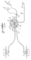
- the actuating device for the parking brake of a motor vehicle shown schematically in the drawing, essentially comprises an application device 1 and a brake cable 3 connecting the application device 1 with the two wheel brake members 2 of the rear axle and a device formed by a planetary gear 4 for selectively connecting the application device 1 to an electric motor 5 or an organ that can be driven by muscle power.
- the planetary gear 4 has a first gear member formed by a sun gear 8 and a second gear member formed by a planet carrier 9, and a third gear member formed by a ring gear 10.
- the third gear member formed by the ring gear 10 has the same construction as the application device 1 formed by a rope pulley.
- the ring gear 10 is alternately driven by the planet gears 12 mounted on the planet carrier 9 by means of axles 11 by the driven planet carrier 9 or the driven sun gear 8, the respective other gear member being fixed.
- a cable pull 15 is driven by means of a hand brake lever 6 or a pedal 14, which in turn acts on a cable pulley 16, which in turn acts automatically with the sun gear 8 or with the aid of a locking mechanism formed from two locking plates 17 and 18 and a counter-holder plate 19.
- the planet carrier 9 is fixed by the electric motor 5 and the worm gear 22 connected downstream thereof and meshing with a drive pinion 21 of the planet carrier 9.
- the sun gear 8 is first fixed, for which purpose in the embodiment according to FIG. 2 a wrap spring 24 which engages around the pinion gear 23 carrying the sun gear 8 is brought into engagement position and thereby the sun gear 8 is fixed .
- a switch for the energy supply of the electric motor 5 can be actuated at the same time, which causes the electric motor 5 to start and thus the drive of the planet carrier 9.
- the switch for the power supply of the electric motor 5 and an actuating button or actuating handle 25 for the on or. Disengaging the wrap spring 24 are designed in the embodiment shown in the same construction.
- the actuating button or the actuating handle 25 are connected to the wrap spring 24 by means of a Bowden cable 26.
- the device for fixed setting the sun gear 8 consists of a pawl tooth segment, the pawl 27 is connected via a Bowden cable 28 to the actuating button or the actuating handle 25 and the toothed segment 29 by means of a further connecting means 30 with the Sun gear 8 is connected.
- a sensor 31 detecting its tensile load is switched on, which determines the prevailing tensile stress values and gives it to a downstream computer 32, which in turn is switched on in a dominant manner in the power supply 35 for the electric motor 5, in such a way that each time the parking brake is released electrically automatic adjustment of the brake cable 3 to compensate for any cable lengthening or brake pad wear and the like.
Landscapes
- Engineering & Computer Science (AREA)
- Transportation (AREA)
- Mechanical Engineering (AREA)
- Braking Elements And Transmission Devices (AREA)
- Braking Arrangements (AREA)
- Braking Systems And Boosters (AREA)
- Mechanical Control Devices (AREA)
- Regulating Braking Force (AREA)
Applications Claiming Priority (2)
| Application Number | Priority Date | Filing Date | Title |
|---|---|---|---|
| DE19800679A DE19800679C2 (de) | 1998-01-10 | 1998-01-10 | Betätigungseinrichtung für eine Feststellbremse |
| DE19800679 | 1998-01-10 |
Publications (3)
| Publication Number | Publication Date |
|---|---|
| EP0928728A2 true EP0928728A2 (fr) | 1999-07-14 |
| EP0928728A3 EP0928728A3 (fr) | 2000-12-13 |
| EP0928728B1 EP0928728B1 (fr) | 2004-01-14 |
Family
ID=7854292
Family Applications (1)
| Application Number | Title | Priority Date | Filing Date |
|---|---|---|---|
| EP98121302A Expired - Lifetime EP0928728B1 (fr) | 1998-01-10 | 1998-11-09 | Dispositif d'actionnement pour frein de stationnement |
Country Status (4)
| Country | Link |
|---|---|
| US (1) | US6193022B1 (fr) |
| EP (1) | EP0928728B1 (fr) |
| CA (1) | CA2257788A1 (fr) |
| DE (2) | DE19800679C2 (fr) |
Cited By (2)
| Publication number | Priority date | Publication date | Assignee | Title |
|---|---|---|---|---|
| WO2001058738A1 (fr) * | 2000-02-11 | 2001-08-16 | Pbr Australia Pty Ltd | Actionneur de frein electrique |
| AU779223B2 (en) * | 2000-02-11 | 2005-01-13 | Bosch Chassis Systems Australia Pty Ltd | Electric brake actuator |
Families Citing this family (22)
| Publication number | Priority date | Publication date | Assignee | Title |
|---|---|---|---|---|
| US6755284B2 (en) | 2001-05-24 | 2004-06-29 | Ventra Group Inc. | Electrically driven parking brake actuation assembly |
| DE20117795U1 (de) * | 2001-10-31 | 2002-03-07 | TRW Automotive Electronics & Components GmbH & Co. KG, 78315 Radolfzell | Antriebseinheit zur Betätigung einer Parkbremse in einem Fahrzeug |
| FR2832970B1 (fr) * | 2001-11-30 | 2004-02-13 | Europ De Fabrications Ind Sefi | Dispositif de commande electrrique d'un frein de stationnement et/ou de secours |
| US6848545B2 (en) * | 2002-07-31 | 2005-02-01 | Ventra Group Inc. | Brake actuation assembly for a vehicle |
| DE10236216B4 (de) * | 2002-08-07 | 2007-09-06 | Fico Cables, S.A., Rubi | Betätigungsmechanismus für eine Feststellbremse |
| US7011188B2 (en) * | 2002-08-28 | 2006-03-14 | Ventra Group Inc. | Cable tension sensing device |
| US20040055832A1 (en) * | 2002-09-19 | 2004-03-25 | Edscha North America | Electronic parking brake with feedback control and cable strain gage |
| TW540475U (en) * | 2002-10-07 | 2003-07-01 | Ching-Shu Chen | Dual braking structure for front wheel hub of bicycle |
| US6978870B2 (en) * | 2003-03-26 | 2005-12-27 | Dura Global Technologies, Inc. | Self adjusting electrically powered parking brake actuator mechanism with manual release |
| DE502004002375D1 (de) * | 2003-04-16 | 2007-02-01 | Siemens Ag | Feststellbremse mit einer seilzugvorrichtung |
| DE10354378A1 (de) * | 2003-11-20 | 2005-06-30 | Zf Friedrichshafen Ag | Vorrichtung zur Lagerung eines Pedalhebels |
| US20060021830A1 (en) * | 2004-07-29 | 2006-02-02 | Lassanske Todd W | Cycling exerciser with single cable actuator for brake and resistance adjustment |
| EP1657120B1 (fr) * | 2004-11-15 | 2007-08-22 | Toklan Toos Ind. MfG. Co. | Système de frein électromécanique pour le stationnement |
| US7267205B2 (en) * | 2005-08-31 | 2007-09-11 | Shimano, Inc. | Apparatus for actuating a bicycle hub brake |
| DE102005053159A1 (de) * | 2005-11-04 | 2007-05-10 | Siemens Ag | Verfahren zur kontinuierlichen Bestimmung der Zugkraft F in einem Seil einer Feststellbremse |
| ES1061382Y (es) * | 2005-11-08 | 2006-06-01 | Batz S Coop | "dispositivo electromecanico para un freno de estacionamiento". |
| DE102005056610A1 (de) * | 2005-11-28 | 2007-05-31 | Siemens Ag | Verfahren zur kontinuierlichen Bestimmung der Zugkraft F in einem Seil einer Feststellbremse |
| KR100722947B1 (ko) * | 2005-12-29 | 2007-05-30 | 에스엘 주식회사 | 유성기어 조립체를 이용한 케이블 구동 장치 및 주차브레이크 시스템 |
| DE102009041498A1 (de) * | 2009-09-14 | 2011-03-24 | Brose Fahrzeugteile Gmbh & Co. Kommanditgesellschaft, Coburg | Feststellvorrichtung zum Arretieren eines Kraftfahrzeugteiles |
| US8052581B1 (en) | 2010-01-05 | 2011-11-08 | Saris Cycling Group, Inc. | Dual actuation mechanism for braking and stopping rotation of a rotating member |
| CN202211806U (zh) * | 2011-08-03 | 2012-05-09 | 吴裕民 | 一种轮椅上坡防倒退装置 |
| US9835233B2 (en) | 2016-01-18 | 2017-12-05 | Kongsberg Interior Systems Ii, Inc. | Gearbox for actuating a component of a vehicle seat |
Citations (1)
| Publication number | Priority date | Publication date | Assignee | Title |
|---|---|---|---|---|
| DE3210402A1 (de) | 1982-03-22 | 1983-09-22 | SWF-Spezialfabrik für Autozubehör Gustav Rau GmbH, 7120 Bietigheim-Bissingen | Bremsanlage, insbesondere fuer kraftfahrzeuge |
Family Cites Families (5)
| Publication number | Priority date | Publication date | Assignee | Title |
|---|---|---|---|---|
| US3814222A (en) * | 1973-01-29 | 1974-06-04 | Gen Motors Corp | Differential and brake assembly with parking brake for differential outputs |
| US4817463A (en) * | 1987-04-14 | 1989-04-04 | Itt Corporation | Electric cable tensioning device |
| US4846316A (en) * | 1987-04-15 | 1989-07-11 | Akebono Brake Industry Co., Ltd. | Hydraulic retarder attached with parking brake |
| DE4205588C2 (de) * | 1992-02-24 | 1995-10-26 | Bayerische Motoren Werke Ag | Feststellbremsanlage |
| TW344725B (en) * | 1995-05-17 | 1998-11-11 | Honda Motor Co Ltd | Brake device for vehicle |
-
1998
- 1998-01-10 DE DE19800679A patent/DE19800679C2/de not_active Expired - Fee Related
- 1998-11-09 EP EP98121302A patent/EP0928728B1/fr not_active Expired - Lifetime
- 1998-11-09 DE DE59810589T patent/DE59810589D1/de not_active Expired - Fee Related
-
1999
- 1999-01-05 CA CA002257788A patent/CA2257788A1/fr not_active Abandoned
- 1999-01-06 US US09/226,822 patent/US6193022B1/en not_active Expired - Fee Related
Patent Citations (1)
| Publication number | Priority date | Publication date | Assignee | Title |
|---|---|---|---|---|
| DE3210402A1 (de) | 1982-03-22 | 1983-09-22 | SWF-Spezialfabrik für Autozubehör Gustav Rau GmbH, 7120 Bietigheim-Bissingen | Bremsanlage, insbesondere fuer kraftfahrzeuge |
Cited By (2)
| Publication number | Priority date | Publication date | Assignee | Title |
|---|---|---|---|---|
| WO2001058738A1 (fr) * | 2000-02-11 | 2001-08-16 | Pbr Australia Pty Ltd | Actionneur de frein electrique |
| AU779223B2 (en) * | 2000-02-11 | 2005-01-13 | Bosch Chassis Systems Australia Pty Ltd | Electric brake actuator |
Also Published As
| Publication number | Publication date |
|---|---|
| DE19800679A1 (de) | 1999-07-15 |
| EP0928728A3 (fr) | 2000-12-13 |
| DE59810589D1 (de) | 2004-02-19 |
| CA2257788A1 (fr) | 1999-07-10 |
| US6193022B1 (en) | 2001-02-27 |
| EP0928728B1 (fr) | 2004-01-14 |
| DE19800679C2 (de) | 2002-08-08 |
Similar Documents
| Publication | Publication Date | Title |
|---|---|---|
| DE19800679C2 (de) | Betätigungseinrichtung für eine Feststellbremse | |
| DE60212375T2 (de) | Elektrischer feststellbremsaktuator | |
| DE69419245T2 (de) | Rollstuhlantrieb | |
| DE4129934C2 (de) | Feststellbremsanlage für Personenkraftwagen | |
| EP2202377A2 (fr) | Entraînement destiné au réglage motorisé d'un élément de réglage d'un véhicule automobile | |
| DE69930760T2 (de) | Handgriff für feststellbremsbedienung | |
| DE19654705A1 (de) | Einstellbares Pedalsystem mit manueller Betätigung für ein Kraftfahrzeug | |
| DE19653961A1 (de) | Fremdkraftbetätigte Feststellbremsanlage für Kraftfahrzeuge, insbesondere Personenkraftwagen | |
| DE10029750C1 (de) | Feststellbremse | |
| DE102004028737A1 (de) | Betätigungssystem für eine Handbremse | |
| DE102006033569B4 (de) | Betätigungsvorrichtung für eine Bremseinrichtung | |
| DE10157462A1 (de) | Feststellbremse | |
| DE19523590A1 (de) | Bremsbetätigungsvorrichtung | |
| DE29800315U1 (de) | Betätigungseinrichtung für eine Feststellbremse | |
| DE19726188A1 (de) | Feststellbremse für Kraftfahrzeuge | |
| DE60002493T2 (de) | Vorrichtung zum fahren eines karts mit den händen für personen mit beinbehinderungen und damit ausgerüstetes kart | |
| DE60204136T2 (de) | Verriegelung einer steuervorrichtung mit einem rand zur verstellung | |
| DE19930973C2 (de) | Nabe mit integriertem dreistufigen Schaltgetriebe | |
| DE29710192U1 (de) | Neigungsverstelleinrichtung für eine Kraftfahrzeugsitz-Rückenlehne | |
| EP0604532B1 (fr) | Dispositif d'entrainement pour l'actionnement de dossiers a positions reglables multiples | |
| EP0442387B1 (fr) | Dispositif de commande pour la commande à distance du réglage de position d'un élévateur hydraulique | |
| EP1102908A2 (fr) | Arret de porte | |
| DE102006016497A1 (de) | Betätigungssystem für eine Feststellbremse | |
| EP0499186A1 (fr) | Servo-commande pour un levier de frein à main | |
| EP1050424A2 (fr) | Dispositif anti-recul pour véhicules |
Legal Events
| Date | Code | Title | Description |
|---|---|---|---|
| PUAI | Public reference made under article 153(3) epc to a published international application that has entered the european phase |
Free format text: ORIGINAL CODE: 0009012 |
|
| 17P | Request for examination filed |
Effective date: 19981109 |
|
| AK | Designated contracting states |
Kind code of ref document: A2 Designated state(s): DE ES FR GB SE |
|
| AX | Request for extension of the european patent |
Free format text: AL;LT;LV;MK;RO;SI |
|
| PUAL | Search report despatched |
Free format text: ORIGINAL CODE: 0009013 |
|
| AK | Designated contracting states |
Kind code of ref document: A3 Designated state(s): AT BE CH CY DE DK ES FI FR GB GR IE IT LI LU MC NL PT SE |
|
| AX | Request for extension of the european patent |
Free format text: AL;LT;LV;MK;RO;SI |
|
| AKX | Designation fees paid |
Free format text: DE ES FR GB SE |
|
| GRAH | Despatch of communication of intention to grant a patent |
Free format text: ORIGINAL CODE: EPIDOS IGRA |
|
| GRAS | Grant fee paid |
Free format text: ORIGINAL CODE: EPIDOSNIGR3 |
|
| GRAA | (expected) grant |
Free format text: ORIGINAL CODE: 0009210 |
|
| AK | Designated contracting states |
Kind code of ref document: B1 Designated state(s): DE ES FR GB SE |
|
| PG25 | Lapsed in a contracting state [announced via postgrant information from national office to epo] |
Ref country code: GB Free format text: LAPSE BECAUSE OF FAILURE TO SUBMIT A TRANSLATION OF THE DESCRIPTION OR TO PAY THE FEE WITHIN THE PRESCRIBED TIME-LIMIT Effective date: 20040114 Ref country code: FR Free format text: LAPSE BECAUSE OF FAILURE TO SUBMIT A TRANSLATION OF THE DESCRIPTION OR TO PAY THE FEE WITHIN THE PRESCRIBED TIME-LIMIT Effective date: 20040114 |
|
| REG | Reference to a national code |
Ref country code: GB Ref legal event code: FG4D Free format text: NOT ENGLISH |
|
| REF | Corresponds to: |
Ref document number: 59810589 Country of ref document: DE Date of ref document: 20040219 Kind code of ref document: P |
|
| PG25 | Lapsed in a contracting state [announced via postgrant information from national office to epo] |
Ref country code: SE Free format text: LAPSE BECAUSE OF FAILURE TO SUBMIT A TRANSLATION OF THE DESCRIPTION OR TO PAY THE FEE WITHIN THE PRESCRIBED TIME-LIMIT Effective date: 20040414 |
|
| PG25 | Lapsed in a contracting state [announced via postgrant information from national office to epo] |
Ref country code: ES Free format text: LAPSE BECAUSE OF FAILURE TO SUBMIT A TRANSLATION OF THE DESCRIPTION OR TO PAY THE FEE WITHIN THE PRESCRIBED TIME-LIMIT Effective date: 20040425 |
|
| GBV | Gb: ep patent (uk) treated as always having been void in accordance with gb section 77(7)/1977 [no translation filed] |
Effective date: 20040114 |
|
| PLBE | No opposition filed within time limit |
Free format text: ORIGINAL CODE: 0009261 |
|
| STAA | Information on the status of an ep patent application or granted ep patent |
Free format text: STATUS: NO OPPOSITION FILED WITHIN TIME LIMIT |
|
| 26N | No opposition filed |
Effective date: 20041015 |
|
| EN | Fr: translation not filed | ||
| PGFP | Annual fee paid to national office [announced via postgrant information from national office to epo] |
Ref country code: DE Payment date: 20050119 Year of fee payment: 7 |
|
| PG25 | Lapsed in a contracting state [announced via postgrant information from national office to epo] |
Ref country code: DE Free format text: LAPSE BECAUSE OF NON-PAYMENT OF DUE FEES Effective date: 20060601 |