EP2202377A2 - Entraînement destiné au réglage motorisé d'un élément de réglage d'un véhicule automobile - Google Patents
Entraînement destiné au réglage motorisé d'un élément de réglage d'un véhicule automobile Download PDFInfo
- Publication number
- EP2202377A2 EP2202377A2 EP09015023A EP09015023A EP2202377A2 EP 2202377 A2 EP2202377 A2 EP 2202377A2 EP 09015023 A EP09015023 A EP 09015023A EP 09015023 A EP09015023 A EP 09015023A EP 2202377 A2 EP2202377 A2 EP 2202377A2
- Authority
- EP
- European Patent Office
- Prior art keywords
- drive
- wrap spring
- adjusting element
- motor
- brake
- Prior art date
- Legal status (The legal status is an assumption and is not a legal conclusion. Google has not performed a legal analysis and makes no representation as to the accuracy of the status listed.)
- Withdrawn
Links
- 230000005540 biological transmission Effects 0.000 claims description 14
- 238000007599 discharging Methods 0.000 claims 1
- 101001017827 Mus musculus Leucine-rich repeat flightless-interacting protein 1 Proteins 0.000 description 2
- 230000001133 acceleration Effects 0.000 description 2
- 229910001060 Gray iron Inorganic materials 0.000 description 1
- XEEYBQQBJWHFJM-UHFFFAOYSA-N Iron Chemical group [Fe] XEEYBQQBJWHFJM-UHFFFAOYSA-N 0.000 description 1
- 238000005266 casting Methods 0.000 description 1
- 230000000694 effects Effects 0.000 description 1
- 230000008092 positive effect Effects 0.000 description 1
- 230000036316 preload Effects 0.000 description 1
- 238000000926 separation method Methods 0.000 description 1
Images


Classifications
-
- E—FIXED CONSTRUCTIONS
- E05—LOCKS; KEYS; WINDOW OR DOOR FITTINGS; SAFES
- E05F—DEVICES FOR MOVING WINGS INTO OPEN OR CLOSED POSITION; CHECKS FOR WINGS; WING FITTINGS NOT OTHERWISE PROVIDED FOR, CONCERNED WITH THE FUNCTIONING OF THE WING
- E05F15/00—Power-operated mechanisms for wings
- E05F15/60—Power-operated mechanisms for wings using electrical actuators
- E05F15/603—Power-operated mechanisms for wings using electrical actuators using rotary electromotors
- E05F15/611—Power-operated mechanisms for wings using electrical actuators using rotary electromotors for swinging wings
- E05F15/63—Power-operated mechanisms for wings using electrical actuators using rotary electromotors for swinging wings operated by swinging arms
-
- E—FIXED CONSTRUCTIONS
- E05—LOCKS; KEYS; WINDOW OR DOOR FITTINGS; SAFES
- E05F—DEVICES FOR MOVING WINGS INTO OPEN OR CLOSED POSITION; CHECKS FOR WINGS; WING FITTINGS NOT OTHERWISE PROVIDED FOR, CONCERNED WITH THE FUNCTIONING OF THE WING
- E05F15/00—Power-operated mechanisms for wings
- E05F15/40—Safety devices, e.g. detection of obstructions or end positions
- E05F15/41—Detection by monitoring transmitted force or torque; Safety couplings with activation dependent upon torque or force, e.g. slip couplings
-
- E—FIXED CONSTRUCTIONS
- E05—LOCKS; KEYS; WINDOW OR DOOR FITTINGS; SAFES
- E05Y—INDEXING SCHEME ASSOCIATED WITH SUBCLASSES E05D AND E05F, RELATING TO CONSTRUCTION ELEMENTS, ELECTRIC CONTROL, POWER SUPPLY, POWER SIGNAL OR TRANSMISSION, USER INTERFACES, MOUNTING OR COUPLING, DETAILS, ACCESSORIES, AUXILIARY OPERATIONS NOT OTHERWISE PROVIDED FOR, APPLICATION THEREOF
- E05Y2201/00—Constructional elements; Accessories therefor
- E05Y2201/20—Brakes; Disengaging means; Holders; Stops; Valves; Accessories therefor
- E05Y2201/21—Brakes
-
- E—FIXED CONSTRUCTIONS
- E05—LOCKS; KEYS; WINDOW OR DOOR FITTINGS; SAFES
- E05Y—INDEXING SCHEME ASSOCIATED WITH SUBCLASSES E05D AND E05F, RELATING TO CONSTRUCTION ELEMENTS, ELECTRIC CONTROL, POWER SUPPLY, POWER SIGNAL OR TRANSMISSION, USER INTERFACES, MOUNTING OR COUPLING, DETAILS, ACCESSORIES, AUXILIARY OPERATIONS NOT OTHERWISE PROVIDED FOR, APPLICATION THEREOF
- E05Y2201/00—Constructional elements; Accessories therefor
- E05Y2201/20—Brakes; Disengaging means; Holders; Stops; Valves; Accessories therefor
- E05Y2201/214—Disengaging means
- E05Y2201/216—Clutches
-
- E—FIXED CONSTRUCTIONS
- E05—LOCKS; KEYS; WINDOW OR DOOR FITTINGS; SAFES
- E05Y—INDEXING SCHEME ASSOCIATED WITH SUBCLASSES E05D AND E05F, RELATING TO CONSTRUCTION ELEMENTS, ELECTRIC CONTROL, POWER SUPPLY, POWER SIGNAL OR TRANSMISSION, USER INTERFACES, MOUNTING OR COUPLING, DETAILS, ACCESSORIES, AUXILIARY OPERATIONS NOT OTHERWISE PROVIDED FOR, APPLICATION THEREOF
- E05Y2201/00—Constructional elements; Accessories therefor
- E05Y2201/20—Brakes; Disengaging means; Holders; Stops; Valves; Accessories therefor
- E05Y2201/23—Actuation thereof
- E05Y2201/232—Actuation thereof by automatically acting means
- E05Y2201/236—Actuation thereof by automatically acting means using force or torque
-
- E—FIXED CONSTRUCTIONS
- E05—LOCKS; KEYS; WINDOW OR DOOR FITTINGS; SAFES
- E05Y—INDEXING SCHEME ASSOCIATED WITH SUBCLASSES E05D AND E05F, RELATING TO CONSTRUCTION ELEMENTS, ELECTRIC CONTROL, POWER SUPPLY, POWER SIGNAL OR TRANSMISSION, USER INTERFACES, MOUNTING OR COUPLING, DETAILS, ACCESSORIES, AUXILIARY OPERATIONS NOT OTHERWISE PROVIDED FOR, APPLICATION THEREOF
- E05Y2201/00—Constructional elements; Accessories therefor
- E05Y2201/40—Motors; Magnets; Springs; Weights; Accessories therefor
- E05Y2201/47—Springs
- E05Y2201/49—Wrap springs
-
- E—FIXED CONSTRUCTIONS
- E05—LOCKS; KEYS; WINDOW OR DOOR FITTINGS; SAFES
- E05Y—INDEXING SCHEME ASSOCIATED WITH SUBCLASSES E05D AND E05F, RELATING TO CONSTRUCTION ELEMENTS, ELECTRIC CONTROL, POWER SUPPLY, POWER SIGNAL OR TRANSMISSION, USER INTERFACES, MOUNTING OR COUPLING, DETAILS, ACCESSORIES, AUXILIARY OPERATIONS NOT OTHERWISE PROVIDED FOR, APPLICATION THEREOF
- E05Y2201/00—Constructional elements; Accessories therefor
- E05Y2201/60—Suspension or transmission members; Accessories therefor
- E05Y2201/622—Suspension or transmission members elements
- E05Y2201/71—Toothed gearing
- E05Y2201/72—Planetary gearing
-
- E—FIXED CONSTRUCTIONS
- E05—LOCKS; KEYS; WINDOW OR DOOR FITTINGS; SAFES
- E05Y—INDEXING SCHEME ASSOCIATED WITH SUBCLASSES E05D AND E05F, RELATING TO CONSTRUCTION ELEMENTS, ELECTRIC CONTROL, POWER SUPPLY, POWER SIGNAL OR TRANSMISSION, USER INTERFACES, MOUNTING OR COUPLING, DETAILS, ACCESSORIES, AUXILIARY OPERATIONS NOT OTHERWISE PROVIDED FOR, APPLICATION THEREOF
- E05Y2201/00—Constructional elements; Accessories therefor
- E05Y2201/60—Suspension or transmission members; Accessories therefor
- E05Y2201/622—Suspension or transmission members elements
- E05Y2201/71—Toothed gearing
- E05Y2201/726—Ring gears; Internal gears
-
- E—FIXED CONSTRUCTIONS
- E05—LOCKS; KEYS; WINDOW OR DOOR FITTINGS; SAFES
- E05Y—INDEXING SCHEME ASSOCIATED WITH SUBCLASSES E05D AND E05F, RELATING TO CONSTRUCTION ELEMENTS, ELECTRIC CONTROL, POWER SUPPLY, POWER SIGNAL OR TRANSMISSION, USER INTERFACES, MOUNTING OR COUPLING, DETAILS, ACCESSORIES, AUXILIARY OPERATIONS NOT OTHERWISE PROVIDED FOR, APPLICATION THEREOF
- E05Y2400/00—Electronic control; Electrical power; Power supply; Power or signal transmission; User interfaces
- E05Y2400/10—Electronic control
- E05Y2400/30—Electronic control of motors
- E05Y2400/3013—Electronic control of motors during manual wing operation
- E05Y2400/3014—Back driving the transmission or motor
-
- E—FIXED CONSTRUCTIONS
- E05—LOCKS; KEYS; WINDOW OR DOOR FITTINGS; SAFES
- E05Y—INDEXING SCHEME ASSOCIATED WITH SUBCLASSES E05D AND E05F, RELATING TO CONSTRUCTION ELEMENTS, ELECTRIC CONTROL, POWER SUPPLY, POWER SIGNAL OR TRANSMISSION, USER INTERFACES, MOUNTING OR COUPLING, DETAILS, ACCESSORIES, AUXILIARY OPERATIONS NOT OTHERWISE PROVIDED FOR, APPLICATION THEREOF
- E05Y2900/00—Application of doors, windows, wings or fittings thereof
- E05Y2900/50—Application of doors, windows, wings or fittings thereof for vehicles
- E05Y2900/53—Type of wing
- E05Y2900/546—Tailboards, tailgates or sideboards opening upwards
Definitions
- the present invention relates to a drive for the motorized adjustment of an adjusting element of a motor vehicle according to the preambles of claims 1 and 14 and a flap assembly according to the preamble of claim 16.
- the well-known drive ( US 3,757,472 A ), from which the invention proceeds, is used for the motorized adjustment of a tailgate of a motor vehicle.
- the known drive is equipped with a drive motor, a drive motor downstream worm gear and a worm gear downstream feed gear.
- the feed gear is designed here as a lever mechanism and serves to generate drive movements.
- the drive train of the drive is not designed to be self-locking.
- the entire drive train to the drive motor even the manual adjustment follows largely slip-free.
- a braking device in the form of a wrap is arranged in the drive train of the drive.
- the wrap is here arranged directly on the worm wheel of the worm gear.
- the dimensions of the wrap spring must be adapted to the dimensions of the worm wheel, which can be unfavorable space.
- Unfavorable in the known drive is the fact that in the case of manual adjustment of the adjustment at extreme, acting on the drive Actuating forces damage to drive components, in particular the worm gear, can not be excluded. Such extreme actuation forces can occur in the event of abusive operation or in an emergency.
- actuating force includes not only forces in the strict sense, but also torques.
- the invention is based on the problem, the known drive in such a way and further develop that its robustness relative to extreme, acting on the drive actuating forces is increased.
- a planetary gear is used as overload clutch in the above sense. This initially has the advantage that not only the function of the overload clutch, but also a gear ratio is realized.
- a ring gear is preferably associated with the ring gear, which holds the ring gear in normal operation and which is hereinafter referred to as "transmission brake device”.
- the function of the transmission brake device goes back to the function of a wrap, which makes the realization of the overload clutch particularly cost.
- a further wrap spring is provided, which is constantly in braking engagement with a drive component, in particular with the drive shaft of the drive motor.
- This wrap is used to accurately adjust the braking behavior of the drive with respect to a manual adjustment. This can be realized, for example, that the adjusting element holds its position in any intermediate position when the drive motor is switched off (claim 10).
- a flap arrangement, in particular a tailgate arrangement, of a motor vehicle according to claim 15 is claimed.
- This further teaching also has independent significance.
- the proposed flap arrangement is equipped with a hinged to the body of the motor vehicle flap and with at least one proposed drive for the motorized adjustment of the flap. Reference may be made to all embodiments relating to the proposed drives as far as they are suitable for describing the assigned flap arrangement.
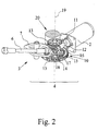
- the drive shown in the drawing is used for the motorized adjustment of a tailgate 1 of a motor vehicle. This is not meant to be limiting. The proposed drive is applicable to all possible adjusting elements of a motor vehicle, as will be explained in detail below.
- the drive is equipped with a drive motor 2 and a feed gear 3 connected downstream of the drive motor 2, which serves to generate drive movements.
- the drive train 4 of the drive is not designed to be self-locking, so that the drive in the assembled state allows a manual adjustment of the adjustment 1, which follows the entire drive train 4 largely slip-free.
- a manual adjustment of the adjusting element 1 causes a corresponding adjustment of the drive train 4 up to the drive motor 2 at normal operational adjustment forces.
- the hereby basically The associated risk of damage to a drive component of the drive train 4 was addressed above.
- an overload clutch 5 is arranged, which reduces the above risk of damage to drive components of the drive train 4.
- the arrangement is such that in the assembled state, a manual adjustment of the adjusting element 1 at an operating force on the drive above a limit actuating force triggers the disengagement of the overload clutch 5.
- a manual adjustment of the adjusting element 1 leads to an actuating force acting on the drive, which is above the limit actuating force, this leads to disengagement of the overload clutch 5.
- This ensures that the drive components seen by the adjusting element 1 "behind" the overload clutch 5 are arranged to be separated from the manual adjustment drive technology.
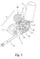
- the feed gear 3 on a push rod 6, which is articulated on the one hand eccentrically on a drivable by the drive motor 2 drive wheel 7 and on the other hand on the adjusting element 1 or, as here, on a coupled to the adjusting element 1 8. It can be seen in Fig. 1 infer that this is coupled to the adjusting element 1 is a hinge lever 8.
- the push rod 6 acts in Fig. 1 essentially in the horizontal direction and thus generates on the hinge lever 8 a torque on the tailgate 1, in view of the structural design and operation of such a push rod drive is allowed on the German utility model DE 20 2004 016 543 U1 referred to by the Applicant, the content of which is the subject of the present application.
- the feed gear 3 has a spindle-spindle nut transmission.
- a spindle drive is preferably arranged where usually the weight of the tailgate 1 counteracting gas spring are.
- the structural design and the operation of such a spindle drive may on the German utility model DE 20 2005 007 154 U1 referred to by the Applicant and which is the subject of the present application.
- the overload clutch 5 is seen as close as possible to the tailgate 1 seen along the drive train 4.
- the overload clutch 5 is arranged in the drive train 4 between the drive motor 2 and the feed gear 3.
- the overload clutch 5 in the drive train 4 is arranged directly on the feed gear 3.
- An advantageous embodiment is equipped with two clutch discs, which are biased against each other and are in frictional engagement with each other.
- the overload clutch 5 at least one coil spring 9.
- wrap springs may on the international patent application WO 2007/014686 Al referenced by the applicant, which is the subject of this application.
- the overload clutch 5 is designed as a wrap spring clutch.
- the wrap 9 is here with its inner surface or outer surface in frictional Engagement with a cylindrical or hollow cylindrical drive part.
- the wrap spring ends are correspondingly coupled to a driven part or at least coupled. Exceeding an acting on the drive limit actuation force leads with appropriate design of the wrap spring for slipping, the wrap 9 relative to the drive element and thus for disengaging the overload clutch. 5
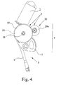
- the overload clutch 5 is not designed as a classic wrap spring clutch, but instead has a planetary gear arranged in the drive train 4, which means that the overload clutch 5 can simultaneously provide a transmission ratio. This regularly leads to a particularly compact arrangement.
- the drive motor 2 is equipped with a drive shaft 11 which carries a drive worm 12.
- the drive worm 12 meshes with a drive wheel 13, which is connected via a further shaft with the sun gear 14 of the planetary gear 10.
- the sun gear 14 meshes in the usual way with planet wheels 15, which are mounted on a planet carrier 16.
- the planet carrier 16 is in turn connected to a drive wheel 17.
- the drive wheel 17 meshes with the above-mentioned drive wheel 7, on which the push rod 6 is articulated eccentrically.
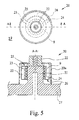
- the transmission brake device 20 is designed as a wrap spring brake. Specifically, the transmission brake device 20 for deriving a braking torque on two brake parts 21, 22, wherein the first brake member 21 is in braking engagement with the inner surface of the wrap spring 9, and wherein the second brake member 22 with the two wrap spring ends 23, 24 into engagement is or can be brought.
- the engagement of the second brake part 22 with both wrap spring ends 23, 24 is necessary in order to realize a corresponding braking behavior in both adjustment directions of the adjustment element 1.
- the first brake member 21 is here and preferably designed as a pin on which the wrap spring 9 is placed.
- the second brake member 22 is pivotally mounted on the first brake member 21 and is not engaged with the outer surface of the wrap spring 9.
- the fact that the second brake wedge 22 has contact surfaces 25, 26 for the wrap spring ends 23, 24 is interesting. Here and preferably, it is such that the second brake member 22, the two wrap spring ends 23,24 for generating a spring bias apart.
- a brake member 21, 22, here the second brake member 22, coupled to the corresponding element, here with the ring gear 18 of the planetary gear 10 and the other brake member, here the first brake member 21 is fixed.
- the first brake member 21 is even formed integrally with the housing 27 of the drive.
- the housing is here and preferably designed as a casting, in particular as a gray cast iron part.
- a predetermined braking behavior of the drive train 4 is provided here and preferably, which prevents an undesired collapse or the like of the adjusting element 1.
- an additional braking device 28 is preferably provided, which is constantly braking with a drive component of the drive train 4 is engaged.
- the drive train 4 of the drive is braked by the friction between the drive components of the drive on the one hand and by the additional brake assembly 28 on the other hand so that the adjusting element 1 holds its position in any intermediate position with the drive motor 2 off.
- the above braking effect must first be overcome in order to be able to achieve a corresponding acceleration of the adjusting element 1.
- the overload clutch 5 disengages and separates the components located behind the overload clutch 5 in terms of drive technology from the manual adjustment.
- the additional braking device 28 is designed as a wrap spring brake with at least one wrap spring 29.
- the wrap spring 29 is arranged on a designed as a shaft drive component 11 of the drive train 4, wherein the loop spring ends 30, 31 are in engagement with a fixed bearing 32.
- a fixed bearing 32 Such an arrangement is exemplary in Fig. 6 shown.
- the functioning of in Fig. 6 The wrap spring brake shown essentially corresponds to the in Fig. 5 shown wrap spring brake. Again, it is preferably such that the two loop spring ends 30, 31 for generating a spring preload, here. by means of the fixed bearing 32, be pressed apart.
- a particularly simple to implement, not shown in the drawing arrangement results from the fact that the wrap spring 29 of the additional brake device 28 on the motor shaft 11 of the drive motor 2, this is arranged to brake.
- the arrangement of the additional brake device 28 has the particular advantage that the applied by the wrap spring 28 braking torque is regularly low, which has a positive effect on the costs associated with the realization of the wrap spring brake 28.
- the proposed drive is applicable to all possible adjusting elements of a motor vehicle.
- the adjusting element is a tailgate 1 of a motor vehicle.
- a single drive can be provided.
- the tailgate 1 to be associated with two drives, each of which engages laterally on the tailgate 1.
- a proposed drive is claimed, wherein it does not necessarily depend on the realization of an overload clutch 5. It is essential here that for adjusting the braking behavior of the drive train 4 with respect to a manual adjustment of the adjusting element 1, an above additional braking device 28 is provided which has at least one wrap spring 29, wherein the wrap spring 29 on a shaft, in particular on the motor shaft 11 the drive motor 2, this is arranged in a braking manner and wherein the loop spring ends 30, 31 are in engagement with a fixed bearing 32.
- a flap arrangement in particular a tailgate assembly, of a motor vehicle is claimed.
- the proposed flap arrangement is with an above-explained, hinged to the body of the motor vehicle hinged flap 1 and at least one proposed drive for motorized adjustment of the flap 1, wherein the drive comprises a drive motor 2 and a drive motor 2 downstream feed gear 3 for generating drive movements.
- the drive comprises a drive motor 2 and a drive motor 2 downstream feed gear 3 for generating drive movements.
Landscapes
- Power-Operated Mechanisms For Wings (AREA)
- Connection Of Motors, Electrical Generators, Mechanical Devices, And The Like (AREA)
Applications Claiming Priority (1)
| Application Number | Priority Date | Filing Date | Title |
|---|---|---|---|
| DE202008016929U DE202008016929U1 (de) | 2008-12-23 | 2008-12-23 | Antrieb zur motorischen Verstellung eines Verstellelements eines Kraftfahrzeugs |
Publications (2)
| Publication Number | Publication Date |
|---|---|
| EP2202377A2 true EP2202377A2 (fr) | 2010-06-30 |
| EP2202377A3 EP2202377A3 (fr) | 2013-08-28 |
Family
ID=42113158
Family Applications (1)
| Application Number | Title | Priority Date | Filing Date |
|---|---|---|---|
| EP09015023.6A Withdrawn EP2202377A3 (fr) | 2008-12-23 | 2009-12-04 | Entraînement destiné au réglage motorisé d'un élément de réglage d'un véhicule automobile |
Country Status (2)
| Country | Link |
|---|---|
| EP (1) | EP2202377A3 (fr) |
| DE (1) | DE202008016929U1 (fr) |
Cited By (7)
| Publication number | Priority date | Publication date | Assignee | Title |
|---|---|---|---|---|
| DK178224B1 (da) * | 2013-06-25 | 2015-09-07 | Fl Holding Aps | Motordrevet døråbner og -lukker med variabel gearing, samt køretøj med døråbner og -lukker |
| DE102014005006A1 (de) | 2014-04-04 | 2015-10-08 | Brose Fahrzeugteile Gmbh & Co. Kg, Hallstadt | Elektrischer Antriebsmotor |
| JP2016514552A (ja) * | 2013-04-05 | 2016-05-23 | ユリウス ブルム ゲー エム ベー ハー | 家具駆動装置 |
| DE102018126350A1 (de) | 2018-10-23 | 2020-04-23 | Schaeffler Technologies AG & Co. KG | Lagerung eines Linearaktors für ein Fahrzeug |
| DE102019119262B3 (de) | 2019-06-05 | 2020-07-23 | PRINZ Kinematics GmbH | Scharnier für eine Fahrzeugtür |
| US10903713B2 (en) | 2015-12-25 | 2021-01-26 | Minebea Mitsumi Inc. | Inner-rotor motor |
| WO2022178451A1 (fr) * | 2021-02-22 | 2022-08-25 | Reell Precision Manufacturing Corporation | Frein de ralentissement à friction à axe parallèle |
Families Citing this family (11)
| Publication number | Priority date | Publication date | Assignee | Title |
|---|---|---|---|---|
| DE102012012398A1 (de) | 2012-06-25 | 2014-01-02 | Brose Fahrzeugteile Gmbh & Co. Kg, Hallstadt | Antrieb zur motorischen Verstellung eines Verstellelements eines Kraftfahrzeugs |
| DE102013109314A1 (de) | 2013-08-28 | 2015-03-05 | Brose Fahrzeugteile Gmbh & Co. Kommanditgesellschaft, Hallstadt | Bremsanordnung für das Bremsen einer Klappe eines Kraftfahrzeugs |
| DE102014117008A1 (de) | 2014-11-20 | 2016-05-25 | Brose Fahrzeugteile Gmbh & Co. Kg, Hallstadt | Spindelantrieb |
| DE102015215630A1 (de) | 2015-08-17 | 2017-02-23 | Brose Fahrzeugteile Gmbh & Co. Kommanditgesellschaft, Bamberg | Vorrichtung zum manuellen und/oder elektromotorischen Verstellen oder Feststellen eines ersten Fahrzeugteils und eines zweiten Fahrzeugteils relativ zueinander |
| DE102015215627A1 (de) * | 2015-08-17 | 2017-02-23 | Brose Fahrzeugteile Gmbh & Co. Kommanditgesellschaft, Bamberg | Vorrichtung zum manuellen und/oder elektromotorischen Verstellen oder Feststellen eines ersten Fahrzeugteils und eines zweiten Fahrzeugteils relativ zueinander |
| DE102015215631A1 (de) | 2015-08-17 | 2017-02-23 | Brose Fahrzeugteile Gmbh & Co. Kommanditgesellschaft, Bamberg | Vorrichtung zum manuellen und/oder elektromotorischen Verstellen oder Feststellen eines ersten Fahrzeugteils und eines zweiten Fahrzeugteils relativ zueinander |
| DE102015119457A1 (de) | 2015-11-11 | 2017-05-11 | Brose Fahrzeugteile Gmbh & Co. Kommanditgesellschaft, Bamberg | Spindelantrieb |
| DE102021130103A1 (de) * | 2021-11-18 | 2023-05-25 | Grass Gmbh | Antriebsvorrichtung mit einem elektrischen Motor zum Bewegen eines beweglichen Möbelteils relativ zu einem Möblekorpus |
| DE102023132037A1 (de) * | 2023-11-17 | 2025-05-22 | Kiekert Aktiengesellschaft | Aufstellvorrichtung für eine Kraftfahrzeugtür |
| DE102024117676A1 (de) * | 2024-06-24 | 2025-12-24 | Brose Fahrzeugteile Se & Co. Kommanditgesellschaft, Bamberg | Schubstangenantrieb für eine Fahrzeugklappe |
| DE102024123218A1 (de) | 2024-08-14 | 2025-08-14 | Brose Fahrzeugteile Se & Co. Kommanditgesellschaft, Bamberg | Antrieb, insbesondere Spindelantrieb, zur Verstellung eines Verschlusselements, insbesondere einer Klappe, eines Kraftfahrzeugs |
Citations (4)
| Publication number | Priority date | Publication date | Assignee | Title |
|---|---|---|---|---|
| US3757472A (en) | 1971-07-21 | 1973-09-11 | Gen Motors Corp | System including bi-directional drive mechanism with reverse drive limit |
| DE202004016543U1 (de) | 2004-10-25 | 2006-03-02 | Brose Schließsysteme GmbH & Co.KG | Antriebsanordnung zur Betätigung der Klappe eines Kraftfahrzeugs |
| DE202005007154U1 (de) | 2005-05-02 | 2006-09-21 | Brose Schließsysteme GmbH & Co.KG | Verstellsystem eines Kraftfahrzeugs zur Verstellung eines Schließteils zum Verschließen einer Öffnung einer Kraftfahrzeugkarosserie |
| WO2007014686A1 (fr) | 2005-07-29 | 2007-02-08 | Brose Fahrzeugteile Gmbh & Co. Kommanditgesellschaft, Coburg | Dispositif de reglage pour un vehicule a moteur |
Family Cites Families (5)
| Publication number | Priority date | Publication date | Assignee | Title |
|---|---|---|---|---|
| DE102004047314A1 (de) * | 2004-09-29 | 2006-03-30 | Siemens Ag | Antrieb zum Schwenken einer Tür oder Klappe |
| DE202004019734U1 (de) * | 2004-12-17 | 2006-04-27 | Brose Schließsysteme GmbH & Co.KG | Klappenanordnung eines Kraftfahrzeugs |
| DE112006001055A5 (de) * | 2005-02-22 | 2008-02-07 | Gross, Beatrix, Dipl.-Ing. | Antrieb zum Bewegen einer Klappe bei einem Kraftfahrzeug |
| DE202006011618U1 (de) * | 2006-07-29 | 2007-12-06 | Brose Fahrzeugteile Gmbh & Co. Kommanditgesellschaft, Coburg | Federelement |
| EP1983134B1 (fr) * | 2007-04-16 | 2009-08-19 | Delphi Technologies, Inc. | Unité d'entraînement |
-
2008
- 2008-12-23 DE DE202008016929U patent/DE202008016929U1/de not_active Expired - Lifetime
-
2009
- 2009-12-04 EP EP09015023.6A patent/EP2202377A3/fr not_active Withdrawn
Patent Citations (4)
| Publication number | Priority date | Publication date | Assignee | Title |
|---|---|---|---|---|
| US3757472A (en) | 1971-07-21 | 1973-09-11 | Gen Motors Corp | System including bi-directional drive mechanism with reverse drive limit |
| DE202004016543U1 (de) | 2004-10-25 | 2006-03-02 | Brose Schließsysteme GmbH & Co.KG | Antriebsanordnung zur Betätigung der Klappe eines Kraftfahrzeugs |
| DE202005007154U1 (de) | 2005-05-02 | 2006-09-21 | Brose Schließsysteme GmbH & Co.KG | Verstellsystem eines Kraftfahrzeugs zur Verstellung eines Schließteils zum Verschließen einer Öffnung einer Kraftfahrzeugkarosserie |
| WO2007014686A1 (fr) | 2005-07-29 | 2007-02-08 | Brose Fahrzeugteile Gmbh & Co. Kommanditgesellschaft, Coburg | Dispositif de reglage pour un vehicule a moteur |
Cited By (14)
| Publication number | Priority date | Publication date | Assignee | Title |
|---|---|---|---|---|
| JP2016514552A (ja) * | 2013-04-05 | 2016-05-23 | ユリウス ブルム ゲー エム ベー ハー | 家具駆動装置 |
| DK178224B1 (da) * | 2013-06-25 | 2015-09-07 | Fl Holding Aps | Motordrevet døråbner og -lukker med variabel gearing, samt køretøj med døråbner og -lukker |
| DE102014005006A1 (de) | 2014-04-04 | 2015-10-08 | Brose Fahrzeugteile Gmbh & Co. Kg, Hallstadt | Elektrischer Antriebsmotor |
| US11211842B2 (en) | 2015-12-25 | 2021-12-28 | Minebea Mitsumi Inc. | Inner-rotor motor with urging structure |
| US11764637B2 (en) | 2015-12-25 | 2023-09-19 | Minebea Mitsumi Inc. | Inner-rotor motor |
| US10903713B2 (en) | 2015-12-25 | 2021-01-26 | Minebea Mitsumi Inc. | Inner-rotor motor |
| DE102018126350A1 (de) | 2018-10-23 | 2020-04-23 | Schaeffler Technologies AG & Co. KG | Lagerung eines Linearaktors für ein Fahrzeug |
| DE102019119262B3 (de) | 2019-06-05 | 2020-07-23 | PRINZ Kinematics GmbH | Scharnier für eine Fahrzeugtür |
| WO2022178451A1 (fr) * | 2021-02-22 | 2022-08-25 | Reell Precision Manufacturing Corporation | Frein de ralentissement à friction à axe parallèle |
| CN116867949A (zh) * | 2021-02-22 | 2023-10-10 | 里尔精密制造公司 | 平行轴线摩擦拖动制动器 |
| JP2024508431A (ja) * | 2021-02-22 | 2024-02-27 | リール・プレシジョン・マニュファクチュアリング・コーポレイション | 平行軸摩擦抗力ブレーキ |
| US20240229907A1 (en) * | 2021-02-22 | 2024-07-11 | Reell Precision Manufacturing Corporation | Parallel axis friction drag brake |
| JP7680785B2 (ja) | 2021-02-22 | 2025-05-21 | リール・プレシジョン・マニュファクチュアリング・コーポレイション | 平行軸摩擦抗力ブレーキ |
| US20250215961A1 (en) * | 2021-02-22 | 2025-07-03 | Reell Precision Manufacturing Corporation | Parallel axis friction drag brake |
Also Published As
| Publication number | Publication date |
|---|---|
| EP2202377A3 (fr) | 2013-08-28 |
| DE202008016929U1 (de) | 2010-05-20 |
Similar Documents
| Publication | Publication Date | Title |
|---|---|---|
| DE202008016929U1 (de) | Antrieb zur motorischen Verstellung eines Verstellelements eines Kraftfahrzeugs | |
| DE60212375T2 (de) | Elektrischer feststellbremsaktuator | |
| EP3488064B1 (fr) | Dispositif d'entraînement d'un ensemble d'éléments de fermeture | |
| DE102014100125A1 (de) | Überlastkupplung | |
| EP1602796B1 (fr) | Dispositif d'entraînement pour une porte ou un hayon de véhicule entraîné par un moteur | |
| DE19800679C2 (de) | Betätigungseinrichtung für eine Feststellbremse | |
| AT502941A1 (de) | Stellantrieb zum antrieb einer klappe eines möbels | |
| DE102016115439A1 (de) | Kraftfahrzeugschlossanordnung | |
| WO2014001032A1 (fr) | Entraînement de réglage motorisé d'un élément de réglage d'un véhicule automobile | |
| DE102014211138A1 (de) | Vorrichtung zum manuellen oder elektromotorischen Verstellen und/oder Feststellen eines ersten Fahrzeugteils und eines zweiten Fahrzeugteils relativ zueinander | |
| DE102013217741A1 (de) | Fahrzeugsitzanordnung | |
| DE102012015650A1 (de) | Antriebsanordnung für die Verstellung einer Klappe eines Kraftfahrzeugs | |
| DE10145843A1 (de) | Kraftfahzeugsitz | |
| EP1109695B1 (fr) | Dispositif de commande servant a regler des elements d'equipement appartenant a un vehicule automobile | |
| DE102019130423A1 (de) | Antriebsstrang | |
| DE10026043C2 (de) | Verschluß für eine Haube oder Tür eines Kraftfahrzeuges | |
| DE202010006168U1 (de) | Klappenanordnung eines Kraftfahrzeugs | |
| DE102014211141A1 (de) | Planetenradgetriebe | |
| DE202008016928U1 (de) | Spindelantrieb | |
| WO2016037934A1 (fr) | Dispositif de rattrapage de jeu pour frein à disque actionné par levier rotatif, et frein à disque pourvu d'un dispositif de rattrapage de jeu | |
| DE19848584B4 (de) | Selbstverstärkende Reibungskupplung | |
| WO2020156619A1 (fr) | Dispositif de freinage | |
| DE102007046916A1 (de) | Kraftfahrzeugschloß | |
| EP1102908B1 (fr) | Arret de porte | |
| DE19832502C2 (de) | Türfeststeller |
Legal Events
| Date | Code | Title | Description |
|---|---|---|---|
| PUAI | Public reference made under article 153(3) epc to a published international application that has entered the european phase |
Free format text: ORIGINAL CODE: 0009012 |
|
| AK | Designated contracting states |
Kind code of ref document: A2 Designated state(s): AT BE BG CH CY CZ DE DK EE ES FI FR GB GR HR HU IE IS IT LI LT LU LV MC MK MT NL NO PL PT RO SE SI SK SM TR |
|
| AX | Request for extension of the european patent |
Extension state: AL BA RS |
|
| PUAL | Search report despatched |
Free format text: ORIGINAL CODE: 0009013 |
|
| AK | Designated contracting states |
Kind code of ref document: A3 Designated state(s): AT BE BG CH CY CZ DE DK EE ES FI FR GB GR HR HU IE IS IT LI LT LU LV MC MK MT NL NO PL PT RO SE SI SK SM TR |
|
| AX | Request for extension of the european patent |
Extension state: AL BA RS |
|
| RIC1 | Information provided on ipc code assigned before grant |
Ipc: E05F 15/12 20060101AFI20130724BHEP |
|
| 17P | Request for examination filed |
Effective date: 20140228 |
|
| RBV | Designated contracting states (corrected) |
Designated state(s): AT BE BG CH CY CZ DE DK EE ES FI FR GB GR HR HU IE IS IT LI LT LU LV MC MK MT NL NO PL PT RO SE SI SK SM TR |
|
| 17Q | First examination report despatched |
Effective date: 20160307 |
|
| STAA | Information on the status of an ep patent application or granted ep patent |
Free format text: STATUS: THE APPLICATION IS DEEMED TO BE WITHDRAWN |
|
| 18D | Application deemed to be withdrawn |
Effective date: 20200701 |