EP0929020A2 - Procédé pour commander une vanne électromagnétique proportionnelle de régulation de pression - Google Patents
Procédé pour commander une vanne électromagnétique proportionnelle de régulation de pression Download PDFInfo
- Publication number
- EP0929020A2 EP0929020A2 EP99300116A EP99300116A EP0929020A2 EP 0929020 A2 EP0929020 A2 EP 0929020A2 EP 99300116 A EP99300116 A EP 99300116A EP 99300116 A EP99300116 A EP 99300116A EP 0929020 A2 EP0929020 A2 EP 0929020A2
- Authority
- EP
- European Patent Office
- Prior art keywords
- spool
- electromagnet
- current
- output port
- amplitude
- Prior art date
- Legal status (The legal status is an assumption and is not a legal conclusion. Google has not performed a legal analysis and makes no representation as to the accuracy of the status listed.)
- Granted
Links
- 238000000034 method Methods 0.000 title claims description 18
- 239000007788 liquid Substances 0.000 claims abstract description 30
- 239000012530 fluid Substances 0.000 claims description 20
- 238000004891 communication Methods 0.000 claims description 6
- 230000000694 effects Effects 0.000 abstract description 15
- 230000003068 static effect Effects 0.000 abstract description 4
- 230000003213 activating effect Effects 0.000 description 5
- 238000001514 detection method Methods 0.000 description 3
- 238000010586 diagram Methods 0.000 description 2
- 230000010349 pulsation Effects 0.000 description 2
- 230000004044 response Effects 0.000 description 2
- 238000012935 Averaging Methods 0.000 description 1
- 241001282135 Poromitra oscitans Species 0.000 description 1
- 206010048232 Yawning Diseases 0.000 description 1
- 230000001133 acceleration Effects 0.000 description 1
- 230000003247 decreasing effect Effects 0.000 description 1
- 230000000994 depressogenic effect Effects 0.000 description 1
- 238000010992 reflux Methods 0.000 description 1
- 230000004043 responsiveness Effects 0.000 description 1
- 230000003313 weakening effect Effects 0.000 description 1
Images



Classifications
-
- B—PERFORMING OPERATIONS; TRANSPORTING
- B60—VEHICLES IN GENERAL
- B60T—VEHICLE BRAKE CONTROL SYSTEMS OR PARTS THEREOF; BRAKE CONTROL SYSTEMS OR PARTS THEREOF, IN GENERAL; ARRANGEMENT OF BRAKING ELEMENTS ON VEHICLES IN GENERAL; PORTABLE DEVICES FOR PREVENTING UNWANTED MOVEMENT OF VEHICLES; VEHICLE MODIFICATIONS TO FACILITATE COOLING OF BRAKES
- B60T8/00—Arrangements for adjusting wheel-braking force to meet varying vehicular or ground-surface conditions, e.g. limiting or varying distribution of braking force
- B60T8/32—Arrangements for adjusting wheel-braking force to meet varying vehicular or ground-surface conditions, e.g. limiting or varying distribution of braking force responsive to a speed condition, e.g. acceleration or deceleration
- B60T8/34—Arrangements for adjusting wheel-braking force to meet varying vehicular or ground-surface conditions, e.g. limiting or varying distribution of braking force responsive to a speed condition, e.g. acceleration or deceleration having a fluid pressure regulator responsive to a speed condition
- B60T8/36—Arrangements for adjusting wheel-braking force to meet varying vehicular or ground-surface conditions, e.g. limiting or varying distribution of braking force responsive to a speed condition, e.g. acceleration or deceleration having a fluid pressure regulator responsive to a speed condition including a pilot valve responding to an electromagnetic force
- B60T8/3615—Electromagnetic valves specially adapted for anti-lock brake and traction control systems
- B60T8/3655—Continuously controlled electromagnetic valves
- B60T8/366—Valve details
- B60T8/3665—Sliding valves
-
- B—PERFORMING OPERATIONS; TRANSPORTING
- B60—VEHICLES IN GENERAL
- B60T—VEHICLE BRAKE CONTROL SYSTEMS OR PARTS THEREOF; BRAKE CONTROL SYSTEMS OR PARTS THEREOF, IN GENERAL; ARRANGEMENT OF BRAKING ELEMENTS ON VEHICLES IN GENERAL; PORTABLE DEVICES FOR PREVENTING UNWANTED MOVEMENT OF VEHICLES; VEHICLE MODIFICATIONS TO FACILITATE COOLING OF BRAKES
- B60T8/00—Arrangements for adjusting wheel-braking force to meet varying vehicular or ground-surface conditions, e.g. limiting or varying distribution of braking force
- B60T8/32—Arrangements for adjusting wheel-braking force to meet varying vehicular or ground-surface conditions, e.g. limiting or varying distribution of braking force responsive to a speed condition, e.g. acceleration or deceleration
- B60T8/34—Arrangements for adjusting wheel-braking force to meet varying vehicular or ground-surface conditions, e.g. limiting or varying distribution of braking force responsive to a speed condition, e.g. acceleration or deceleration having a fluid pressure regulator responsive to a speed condition
- B60T8/36—Arrangements for adjusting wheel-braking force to meet varying vehicular or ground-surface conditions, e.g. limiting or varying distribution of braking force responsive to a speed condition, e.g. acceleration or deceleration having a fluid pressure regulator responsive to a speed condition including a pilot valve responding to an electromagnetic force
-
- B—PERFORMING OPERATIONS; TRANSPORTING
- B60—VEHICLES IN GENERAL
- B60T—VEHICLE BRAKE CONTROL SYSTEMS OR PARTS THEREOF; BRAKE CONTROL SYSTEMS OR PARTS THEREOF, IN GENERAL; ARRANGEMENT OF BRAKING ELEMENTS ON VEHICLES IN GENERAL; PORTABLE DEVICES FOR PREVENTING UNWANTED MOVEMENT OF VEHICLES; VEHICLE MODIFICATIONS TO FACILITATE COOLING OF BRAKES
- B60T8/00—Arrangements for adjusting wheel-braking force to meet varying vehicular or ground-surface conditions, e.g. limiting or varying distribution of braking force
- B60T8/32—Arrangements for adjusting wheel-braking force to meet varying vehicular or ground-surface conditions, e.g. limiting or varying distribution of braking force responsive to a speed condition, e.g. acceleration or deceleration
- B60T8/34—Arrangements for adjusting wheel-braking force to meet varying vehicular or ground-surface conditions, e.g. limiting or varying distribution of braking force responsive to a speed condition, e.g. acceleration or deceleration having a fluid pressure regulator responsive to a speed condition
- B60T8/42—Arrangements for adjusting wheel-braking force to meet varying vehicular or ground-surface conditions, e.g. limiting or varying distribution of braking force responsive to a speed condition, e.g. acceleration or deceleration having a fluid pressure regulator responsive to a speed condition having expanding chambers for controlling pressure, i.e. closed systems
- B60T8/4208—Debooster systems
- B60T8/4225—Debooster systems having a fluid actuated expansion unit
-
- B—PERFORMING OPERATIONS; TRANSPORTING
- B60—VEHICLES IN GENERAL
- B60T—VEHICLE BRAKE CONTROL SYSTEMS OR PARTS THEREOF; BRAKE CONTROL SYSTEMS OR PARTS THEREOF, IN GENERAL; ARRANGEMENT OF BRAKING ELEMENTS ON VEHICLES IN GENERAL; PORTABLE DEVICES FOR PREVENTING UNWANTED MOVEMENT OF VEHICLES; VEHICLE MODIFICATIONS TO FACILITATE COOLING OF BRAKES
- B60T8/00—Arrangements for adjusting wheel-braking force to meet varying vehicular or ground-surface conditions, e.g. limiting or varying distribution of braking force
- B60T8/32—Arrangements for adjusting wheel-braking force to meet varying vehicular or ground-surface conditions, e.g. limiting or varying distribution of braking force responsive to a speed condition, e.g. acceleration or deceleration
- B60T8/34—Arrangements for adjusting wheel-braking force to meet varying vehicular or ground-surface conditions, e.g. limiting or varying distribution of braking force responsive to a speed condition, e.g. acceleration or deceleration having a fluid pressure regulator responsive to a speed condition
- B60T8/50—Arrangements for adjusting wheel-braking force to meet varying vehicular or ground-surface conditions, e.g. limiting or varying distribution of braking force responsive to a speed condition, e.g. acceleration or deceleration having a fluid pressure regulator responsive to a speed condition having means for controlling the rate at which pressure is reapplied to or released from the brake
- B60T8/5018—Pressure reapplication using restrictions
- B60T8/5025—Pressure reapplication using restrictions in hydraulic brake systems
- B60T8/5037—Pressure reapplication using restrictions in hydraulic brake systems closed systems
- B60T8/5043—Pressure reapplication using restrictions in hydraulic brake systems closed systems debooster systems
-
- G—PHYSICS
- G05—CONTROLLING; REGULATING
- G05D—SYSTEMS FOR CONTROLLING OR REGULATING NON-ELECTRIC VARIABLES
- G05D16/00—Control of fluid pressure
- G05D16/20—Control of fluid pressure characterised by the use of electric means
- G05D16/2006—Control of fluid pressure characterised by the use of electric means with direct action of electric energy on controlling means
- G05D16/2013—Control of fluid pressure characterised by the use of electric means with direct action of electric energy on controlling means using throttling means as controlling means
- G05D16/2024—Control of fluid pressure characterised by the use of electric means with direct action of electric energy on controlling means using throttling means as controlling means the throttling means being a multiple-way valve
-
- Y—GENERAL TAGGING OF NEW TECHNOLOGICAL DEVELOPMENTS; GENERAL TAGGING OF CROSS-SECTIONAL TECHNOLOGIES SPANNING OVER SEVERAL SECTIONS OF THE IPC; TECHNICAL SUBJECTS COVERED BY FORMER USPC CROSS-REFERENCE ART COLLECTIONS [XRACs] AND DIGESTS
- Y10—TECHNICAL SUBJECTS COVERED BY FORMER USPC
- Y10T—TECHNICAL SUBJECTS COVERED BY FORMER US CLASSIFICATION
- Y10T137/00—Fluid handling
- Y10T137/0318—Processes
- Y10T137/0396—Involving pressure control
-
- Y—GENERAL TAGGING OF NEW TECHNOLOGICAL DEVELOPMENTS; GENERAL TAGGING OF CROSS-SECTIONAL TECHNOLOGIES SPANNING OVER SEVERAL SECTIONS OF THE IPC; TECHNICAL SUBJECTS COVERED BY FORMER USPC CROSS-REFERENCE ART COLLECTIONS [XRACs] AND DIGESTS
- Y10—TECHNICAL SUBJECTS COVERED BY FORMER USPC
- Y10T—TECHNICAL SUBJECTS COVERED BY FORMER US CLASSIFICATION
- Y10T137/00—Fluid handling
- Y10T137/8593—Systems
- Y10T137/86493—Multi-way valve unit
- Y10T137/86718—Dividing into parallel flow paths with recombining
- Y10T137/86759—Reciprocating
- Y10T137/86767—Spool
- Y10T137/86775—With internal passage
Definitions
- This invention relates to a method of controlling a spool-valve type, electromagnetic proportional pressure control valve used for accurate control of brake fluid pressure or the like.
- Electromagnetic proportional pressure control valves have a driving means comprising an electromagnet and a spring.
- the driving means moves a spool to a position corresponding to its driving force, thereby controlling the fluid pressure applied to a load to a valve corresponding to the driving force of the driving means.
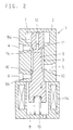
- a typical electromagnetic proportional pressure control valve is shown in Fig. 2.
- the electromagnetic proportional pressure control valve 1 of Fig. 2 comprises a housing 2, a spool 9, a reaction pin 12 inserted at one end of the spool 9, a spring 13 for biasing the spool, and an electromagnet 14 for biasing, i.e. pulling, the spool 9 in the direction opposite to the direction in which the spool is biased by the spring 13.
- the housing 2 has a spool guide bore 3 in which is substantially liquid-tightly and slidably received the spool 9, a supply port 4, an output port 5 and an exhaust port 6 all opening to the bore 3 at its intermediate portions, and first and second fluid chambers 7, 8 into which one and the other ends of the spool 9 protrude, respectively.
- the spool 9 has a surface passage 10, and an internal passage 11 kept in communication with the load port 5.
- the internal passage 11 has one end open to the first fluid chamber 7, and at this end, the reaction pin 12 is substantially liquid-tightly inserted in the passage 11.
- a difference equal to the sectional area of the reaction pin is created between the area for bearing fluid pressure that urges the spool 9 toward the first fluid chamber 7 and the area for bearing fluid pressure that urges the spool toward the second fluid chamber 8.
- the spool 9 is thus biased downward in the figure under a thrust which is equal to the abovesaid difference in area multiplied by the pressure at the load port 5.
- a first valve portion 15 is formed to open and shut off communication between the supply port 4 and the output port 5.
- a second valve portion 16 is formed to open and shut off communication between the output port 5 and the exhaust port 6. The degree of opening of each of the first and second valves 15, 16 changes with the spool position.
- Fpr in the above equation is given by: (P2 - P3) ⁇ S
- P2 is the pressure at the output port 5 (load pressure)
- P3 is the reservoir pressure
- S is the sectional area of the reaction pin 12.
- Fig. 1 shows an automotive brake system including this electromagnetic proportional pressure control valve.
- the supply port 4 is connected to a fluid pressure source (pump 24)
- the output port 5 is connected to a wheel brake 22
- the exhaust port 6 and the first and second fluid chambers 7, 8 are connected to a reservoir 25.
- the valve 1 controls fluid pressure supplied to the wheel brake 22 for antilock control or other vehicle behavior control.
- the illustrated brake system includes a shutoff valve 23 disposed between the master cylinder 21 and the wheel brake 22.
- the valve 23 is kept open by the pressure of an accumulator 26.
- the electromagnetic proportional pressure control valve 1 indirectly controls the pressure in the wheel brake 22 by controlling the fluid supply pressure to the shutoff valve 23.
- a dither that is, force having a controlled amplitude and frequency
- a dither that is, force having a controlled amplitude and frequency
- Such a dither is produced by a current created by superimposing an alternating current (which will be referred to as dither current) on the current supplied to the electromagnet so that the center of amplitude of the former will be on the latter current.
- dither current an alternating current
- the dither effect (that is, spool vibrating power) tends to weaken due to decreased ratio of the solenoid force Fsol to the current I supplied (Fsol/I).
- the amplitude of the dither current is increased so that a sufficient dither effect is achievable in these regions, the dither effect in other regions will be too strong, that is, the spool tends to vibrate excessively.
- Examples of this invention provide a method of controlling an electromagnetic proportional pressure control valve which can substantially level the dither effect over the entire control region.
- a dither current having an amplitude whose center is at a current supplied to the electromagnet is superimposed on the current to vibrate the spool with an amplitude small enough not to affect a liquid pressure controlled by the spool, and that in a control region where the ratio of the force Fsol produced by the electromagnet to the current I supplied to the electromagnet, i.e. Fsol/I is smaller than in other regions, the dither current is controlled such that its amplitude is greater or its frequency is lower than in the other regions.
- a temperature detecting means is added to detect the temperature of the liquid and one of the following two methods is adopted,
- This invention is applicable to not only the electromagnetic proportional pressure control valve shown in Fig. 2, but also to any electromagnetic proportional pressure control valve which has a spool moved to a point where the forces applied to both ends thereof balance with each other by the magnetic force of the electromagnet to control the liquid pressure at an output port to a value corresponding to the spool driving force.
- the spool vibrating force By increasing the amplitude of the dither current or reducing its frequency, the spool vibrating force increases.
- PWM pulse width modulation
- the spool vibrating force increases by lowering the frequency of pulse width modulation.
- the dither effect is strengthened in a region where the Fsol/I ratio is small to smooth the dither effect over the entire control region. It is thus possible to prevent worsening of the spool response due to weakening of the dither effect or pulsation of the liquid pressure due to excessive dither effect in a part of the control region.
- the amplitude or frequency of the spool-vibrating dither current, or the frequency of the pulsating component of the spool-vibrating, PWM-controlled current is changed according to the temperature detected by a temperature detector. It is thus possible to suppress change in responsiveness of the spool due to change in the liquid viscosity.
- the method according to this example is carried out using control software and a simple drive control device shown in Fig. 3.
- This device comprises a microcomputer 17, a coil activating circuit 18, a current detector means 19 for detecting the current flowing through an exciting coil 14a of the electromagnet 14 of Fig. 1, and an A/D converter 20.
- Fig. 4 shows an example of control for vibrating the spool 9 of the electromagnetic proportional pressure control valve 1 of Fig. 1 by applying a dither current.
- the microcomputer 17 calculates an output current I necessary to control the fluid pressure at the output port 5 to a target value when it judges (based on output signals from unillustrated vehicle behavior detection sensors such as wheel speed sensors, acceleration sensors and yaw sensors for detecting yawning of the vehicle) that the wheel brake 22 (see Fig. 1) needs pressure adjustment.
- unillustrated vehicle behavior detection sensors such as wheel speed sensors, acceleration sensors and yaw sensors for detecting yawning of the vehicle
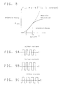
- the microcomputer 17 also determines if the current I is in a region where the dither effect tends to weaken, e.g. in one of the region where the current is greater than I 1 (Fig. 8) and the region where it is smaller than I 2 , and if out of these regions, controls the coil activating circuit 18 so that a current having a waveform formed by superimposing a dither current having a predetermined amplitude and frequency (such as shown in Fig. 9A) on the calculated current I will be supplied to the exciting coil 14a in Fig. 3 (this control is a feedback control in which the detection signal from the current detection means 19 is inputted).
- the microcomputer controls the coil activating circuit 18 to increase the amplitude of the dither current to a level higher than the amplitude when I 1 ⁇ I ⁇ I 2 (as shown in Fig. 9B) or to reduce the frequency of the dither current to a level lower than the frequency when I 1 ⁇ I ⁇ I 2 (as shown in Fig. 9C) so that a current having a waveform formed by superimposing the corrected dither current on the current I will flow through the exciting coil 14a of Fig. 3.
- the supply of the dither current may be started when e.g. the brake pedal is depressed.
- the spool 9 since the spool 9 has already been vibrated with a small amplitude by the time when pressure adjustment is started (at this time, no normal current I is being supplied), the spool 9 can begin to move smoothly.
- the waveforms of the corrected dither currents used in the regions under I 1 and over I 2 may have constant amplitudes and frequencies as shown in Figs. 9B and 9C, within such a range that the dither effect will not be too small or too large, or may be changed gradually with increase or decrease of the current being supplied. As seen in Fig.
- the electromagnet 14 may be controlled by pulse width modulation (PWM) method.
- PWM pulse width modulation
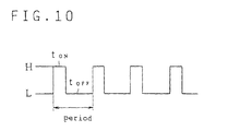
- a basic waveform of a current produced by PWM control (in which the current supplied to the electromagnet is controlled by adjusting the on-off ratio of a power element) is shown in Fig. 10.
- This current waveform is ordinarily smoothed using an inductance and a reflux diode. But still, it is a pulsating waveform. In order to eliminate the influence of pulsation, the current is converted to a highfrequency current. But by lowering the frequency, it is possible to vibrate the spool 9 using the pulsating component.
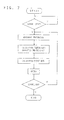
- control flowchart is as shown in Fig. 5.
- a temperature detecting means should be added to detect the temperature of the liquid to be controlled.
- the temperature detecting means may be either of a type that directly detects the liquid temperature or a type that indirectly detects it (if there is a portion whose temperature changes proportionally). If there is no problem in accuracy, the temperature detecting means may be of a type that estimates the temperature based on temperature-related sensor information.
- the waveform of the current controlled by the dither current or PWM may be changed. If the spool is to be vibrated by applying a dither current, the amplitude or frequency of the temperature-corrected dither current is calculated as shown in Fig. 6, and the coil activating circuit 18 is controlled such that a current having a waveform to which the dither current is added will flow through the exciting coil 14a.
- the temperature-corrected PWM frequency is calculated as shown in Fig. 7, and taking it into account an output duty is calculated to control the coil activating circuit 18. If the amplitude of dither current is to be changed, it is changed such that the lower the temperature, the greater the amplitude. If the frequency of the dither current or the PWM frequency is to be changed, they are changed such that the lower the temperature, the lower the frequency.
- any change in the dither current due to changes in the characteristics of the electromagnet and the liquid viscosity is corrected by changing the amplitude or frequency of the dither current, or the frequency of a current suppressed by PWM method.
Landscapes
- Physics & Mathematics (AREA)
- Engineering & Computer Science (AREA)
- Fluid Mechanics (AREA)
- Transportation (AREA)
- Mechanical Engineering (AREA)
- Electromagnetism (AREA)
- General Physics & Mathematics (AREA)
- Automation & Control Theory (AREA)
- Magnetically Actuated Valves (AREA)
- Control Of Fluid Pressure (AREA)
- Analogue/Digital Conversion (AREA)
Applications Claiming Priority (2)
| Application Number | Priority Date | Filing Date | Title |
|---|---|---|---|
| JP328798 | 1998-01-09 | ||
| JP10003287A JPH11202947A (ja) | 1998-01-09 | 1998-01-09 | 電磁比例圧力制御弁の駆動制御方法 |
Publications (3)
| Publication Number | Publication Date |
|---|---|
| EP0929020A2 true EP0929020A2 (fr) | 1999-07-14 |
| EP0929020A3 EP0929020A3 (fr) | 2000-07-05 |
| EP0929020B1 EP0929020B1 (fr) | 2004-08-25 |
Family
ID=11553196
Family Applications (1)
| Application Number | Title | Priority Date | Filing Date |
|---|---|---|---|
| EP99300116A Expired - Lifetime EP0929020B1 (fr) | 1998-01-09 | 1999-01-07 | Procédé pour commander une vanne électromagnétique proportionnelle de régulation de pression |
Country Status (5)
| Country | Link |
|---|---|
| US (1) | US6155654A (fr) |
| EP (1) | EP0929020B1 (fr) |
| JP (1) | JPH11202947A (fr) |
| CN (1) | CN1105343C (fr) |
| DE (1) | DE69919604T2 (fr) |
Cited By (8)
| Publication number | Priority date | Publication date | Assignee | Title |
|---|---|---|---|---|
| EP1130300A1 (fr) * | 2000-02-29 | 2001-09-05 | Whirlpool Corporation | Méthode de commande pour des vannes avec modulation de largeur d'impulsions |
| WO2006037715A1 (fr) * | 2004-10-06 | 2006-04-13 | Siemens Aktiengesellschaft | Procede et dispositif pour determiner un signal pwm sur lequel une frequence de tremblement est superposee pour commander une vanne magnetique |
| WO2009155154A1 (fr) * | 2008-06-18 | 2009-12-23 | Ge Fanuc Intelligent Platforms, Inc. | Procédés et appareil de commande du fonctionnement d’un dispositif de commande |
| WO2010000546A1 (fr) | 2008-07-02 | 2010-01-07 | Robert Bosch Gmbh | Procédé pour actionner une soupape à fluide avec un mouvement de soupape oscillant |
| ITPD20110261A1 (it) * | 2011-08-03 | 2013-02-04 | Sit La Precisa Spa Con Socio Unico | Metodo e sistema di controllo di una unità valvolare modulante includente un elettromagnete |
| WO2017060008A1 (fr) * | 2015-10-08 | 2017-04-13 | Robert Bosch Gmbh | Procédé d'activation d'une soupape électromagnétique et système fluidique associé |
| WO2017084964A1 (fr) * | 2015-11-20 | 2017-05-26 | Zf Friedrichshafen Ag | Surveillance du courant sur un consommateur |
| EP4459133A4 (fr) * | 2021-12-28 | 2025-11-12 | Kubota Kk | Système hydraulique de machine de travail |
Families Citing this family (44)
| Publication number | Priority date | Publication date | Assignee | Title |
|---|---|---|---|---|
| DE19710173A1 (de) * | 1997-03-12 | 1998-09-17 | Itt Mfg Enterprises Inc | Druckregelventil |
| EP1065678A1 (fr) * | 1999-01-20 | 2001-01-03 | Unisia Jecs Corporation | Appareil de commande a robinet electromagnetique et appareil de commande de frein |
| KR100771267B1 (ko) * | 2000-03-02 | 2007-10-29 | 지멘스 악티엔게젤샤프트 | 고정 듀티비를 사용하여 작동기를 제어하기 위한 방법 |
| JP4366835B2 (ja) * | 2000-05-26 | 2009-11-18 | アイシン精機株式会社 | 電磁弁 |
| JP2002081570A (ja) * | 2000-09-04 | 2002-03-22 | Aisin Aw Co Ltd | リニアソレノイドバルブの調整装置及び調整方法 |
| US6866348B2 (en) * | 2001-04-05 | 2005-03-15 | Mico, Inc. | Electronically controlled full power brake valve |
| US6736094B2 (en) * | 2002-06-17 | 2004-05-18 | Borgwarner Inc. | VCT solenoid dither frequency control |
| DE10242790A1 (de) * | 2002-09-14 | 2004-03-25 | Robert Bosch Gmbh | Verfahren zum Regeln des Stroms durch ein elektromagnetisches Stellglied |
| US20040144943A1 (en) * | 2003-01-28 | 2004-07-29 | Everett William F. | Electromagnetically actuated proportional flow control system |
| US7156115B2 (en) * | 2003-01-28 | 2007-01-02 | Lancer Partnership, Ltd | Method and apparatus for flow control |
| JP2004301224A (ja) * | 2003-03-31 | 2004-10-28 | Denso Corp | デューティ比制御装置 |
| US7007915B2 (en) * | 2004-03-10 | 2006-03-07 | Masco Corporation Of Indiana | Low energy fluid actuator control element |
| US6968860B1 (en) | 2004-08-05 | 2005-11-29 | Masco Corporation Of Indiana | Restricted flow hands-free faucet |
| JP4378637B2 (ja) * | 2005-03-04 | 2009-12-09 | アイシン精機株式会社 | 流体制御弁及び弁開閉時期制御装置 |
| JP2007011984A (ja) * | 2005-07-04 | 2007-01-18 | Advanced Energy Japan Kk | 排気装置の圧力制御システム |
| JP2007040361A (ja) * | 2005-08-02 | 2007-02-15 | Bosch Corp | 電磁弁駆動制御方法 |
| US20080099705A1 (en) * | 2006-10-25 | 2008-05-01 | Enfield Technologies, Llc | Retaining element for a mechanical component |
| JP2008215145A (ja) * | 2007-03-01 | 2008-09-18 | Yanmar Co Ltd | 電子制御ガバナ |
| JP4578492B2 (ja) * | 2007-03-01 | 2010-11-10 | ヤンマー株式会社 | 電子制御ガバナ |
| US8176895B2 (en) | 2007-03-01 | 2012-05-15 | Yanmar Co., Ltd. | Electronic control governor |
| JP2008304041A (ja) * | 2007-06-11 | 2008-12-18 | Aisin Aw Co Ltd | 移動不良検出装置 |
| JP4640386B2 (ja) * | 2007-07-20 | 2011-03-02 | トヨタ自動車株式会社 | ブレーキ装置およびブレーキ制御方法 |
| DE102007045028B3 (de) * | 2007-09-20 | 2008-07-24 | Festo Ag & Co. | Magnetventil mit einer Handhilfsbetätigung |
| DE102008013602B4 (de) * | 2008-03-11 | 2019-07-04 | Robert Bosch Gmbh | Verfahren zum Ansteuern einer Vielzahl von Ventilen und Steuerblock mit einer Vielzahl von Ventilen |
| CN101691890B (zh) * | 2009-10-13 | 2011-08-31 | 金仁召 | 一种节流阀 |
| EP2528789B1 (fr) * | 2010-01-28 | 2016-07-13 | Continental Teves AG & Co. oHG | Appareil de commande électronique pour un système de freinage |
| JP5469008B2 (ja) * | 2010-07-16 | 2014-04-09 | 本田技研工業株式会社 | 摩擦係合要素の制御方法 |
| CN103003605B (zh) * | 2010-08-06 | 2014-07-30 | 川崎重工业株式会社 | 气体用调压阀 |
| JP5406993B2 (ja) * | 2010-08-06 | 2014-02-05 | 川崎重工業株式会社 | ガス用調圧弁 |
| WO2013056429A1 (fr) * | 2011-10-18 | 2013-04-25 | 中联重科股份有限公司 | Système de commande permettant de contrôler une électrovanne et procédé de commande associé |
| DE102012206419B4 (de) * | 2012-04-19 | 2021-08-12 | Magna Pt B.V. & Co. Kg | Steuerung für ein Druckregelventil |
| WO2013176003A1 (fr) * | 2012-05-23 | 2013-11-28 | 株式会社 島津製作所 | Dispositif de commande pour manipulation de marchandises |
| KR101967306B1 (ko) * | 2014-05-21 | 2019-05-15 | 주식회사 만도 | 솔레노이드 밸브 제어장치 및 그 제어방법 |
| CN104075017B (zh) * | 2014-06-27 | 2016-03-02 | 安徽江淮汽车股份有限公司 | 一种电磁阀颤振控制方法及系统 |
| EP3002026A1 (fr) * | 2014-09-30 | 2016-04-06 | Shenzhen Mindray Bio-Medical Electronics Co., Ltd. | Système et procédé de stabilisation d'un moteur à bobine acoustique |
| EP3121444B1 (fr) | 2015-07-24 | 2019-10-23 | Artemis Intelligent Power Limited | Machine de travail de fluides et procédé d'exploitation d'une machine de travail de fluides |
| JP6641152B2 (ja) * | 2015-10-22 | 2020-02-05 | 株式会社Soken | バルブ装置 |
| DE102015016846A1 (de) * | 2015-12-23 | 2017-06-29 | Hydac Fluidtechnik Gmbh | Ventil, insbesondere 4/2-Wegeschieberventil |
| JP6622615B2 (ja) * | 2016-02-16 | 2019-12-18 | 株式会社Soken | 油圧制御装置 |
| US9968033B2 (en) * | 2016-06-21 | 2018-05-15 | Macdon Industries Ltd. | Crop machine with an electronically controlled hydraulic cylinder flotation system |
| US10139375B2 (en) * | 2016-09-01 | 2018-11-27 | Caterpillar Inc. | Methods and systems for monitoring quality of hydraulic fluid in electro-hydraulic (EH) valve |
| JP6874518B2 (ja) * | 2017-05-12 | 2021-05-19 | 株式会社デンソー | 電流制御装置 |
| JP7468324B2 (ja) * | 2020-12-08 | 2024-04-16 | トヨタ自動車株式会社 | リニアソレノイドバルブの制御装置 |
| CN112901721B (zh) * | 2021-02-04 | 2022-07-12 | 中国工程物理研究院总体工程研究所 | 电磁式自动平衡头驱动方法 |
Family Cites Families (11)
| Publication number | Priority date | Publication date | Assignee | Title |
|---|---|---|---|---|
| US3709253A (en) * | 1970-09-23 | 1973-01-09 | Marotta Scientific Controls | Valve control with dither |
| JPS53121163A (en) * | 1977-03-31 | 1978-10-23 | Hitachi Ltd | Electromechanical converter |
| JPS56127115A (en) * | 1980-03-08 | 1981-10-05 | Ckd Controls Ltd | Gas flow rate control system |
| JP2615095B2 (ja) * | 1987-12-01 | 1997-05-28 | 三菱重工業株式会社 | コントロールバルブの制御方法 |
| JPH07101070B2 (ja) * | 1988-02-02 | 1995-11-01 | 日産自動車株式会社 | 電磁比例型制御弁の制御装置 |
| JP2658432B2 (ja) * | 1988-12-01 | 1997-09-30 | ダイキン工業株式会社 | 油圧制御装置 |
| JP3443832B2 (ja) * | 1991-05-21 | 2003-09-08 | ダイキン工業株式会社 | チャック圧制御装置 |
| US5445446A (en) * | 1992-09-21 | 1995-08-29 | Unisia Jecs Corporation | Fluid pressure control valve |
| US5667285A (en) * | 1995-07-28 | 1997-09-16 | General Motors Corporation | Central hydraulics brake system |
| DE19540021A1 (de) * | 1995-10-27 | 1997-04-30 | Bosch Gmbh Robert | Ventil zum dosierten Einleiten von aus einem Brennstofftank einer Brennkraftmaschine verflüchtigtem Brennstoffdampf |
| DE19647432C1 (de) * | 1996-11-15 | 1998-02-12 | Honeywell Bv | Steuerschaltung für ein Gasmagnetventil |
-
1998
- 1998-01-09 JP JP10003287A patent/JPH11202947A/ja active Pending
- 1998-12-30 US US09/222,917 patent/US6155654A/en not_active Expired - Fee Related
- 1998-12-30 CN CN98126564A patent/CN1105343C/zh not_active Expired - Fee Related
-
1999
- 1999-01-07 EP EP99300116A patent/EP0929020B1/fr not_active Expired - Lifetime
- 1999-01-07 DE DE69919604T patent/DE69919604T2/de not_active Expired - Fee Related
Non-Patent Citations (1)
| Title |
|---|
| None |
Cited By (17)
| Publication number | Priority date | Publication date | Assignee | Title |
|---|---|---|---|---|
| EP1130300A1 (fr) * | 2000-02-29 | 2001-09-05 | Whirlpool Corporation | Méthode de commande pour des vannes avec modulation de largeur d'impulsions |
| US7853360B2 (en) | 2004-10-06 | 2010-12-14 | Continental Automotive Gmbh | Method and device for determining a PWM signal on which a dither frequency is superimposed in order to control a solenoid valve |
| WO2006037715A1 (fr) * | 2004-10-06 | 2006-04-13 | Siemens Aktiengesellschaft | Procede et dispositif pour determiner un signal pwm sur lequel une frequence de tremblement est superposee pour commander une vanne magnetique |
| WO2009155154A1 (fr) * | 2008-06-18 | 2009-12-23 | Ge Fanuc Intelligent Platforms, Inc. | Procédés et appareil de commande du fonctionnement d’un dispositif de commande |
| US9027587B2 (en) | 2008-07-02 | 2015-05-12 | Robert Bosch Gmbh | Method for operating a fluid valve via an oscillating valve motion |
| DE102008040062A1 (de) | 2008-07-02 | 2010-01-07 | Robert Bosch Gmbh | Verfahren zum Betreiben eines Fluidventils mit einer oszillierenden Ventilbewegung |
| WO2010000546A1 (fr) | 2008-07-02 | 2010-01-07 | Robert Bosch Gmbh | Procédé pour actionner une soupape à fluide avec un mouvement de soupape oscillant |
| ITPD20110261A1 (it) * | 2011-08-03 | 2013-02-04 | Sit La Precisa Spa Con Socio Unico | Metodo e sistema di controllo di una unità valvolare modulante includente un elettromagnete |
| WO2013017346A1 (fr) * | 2011-08-03 | 2013-02-07 | Sit La Precisa S.P.A. Con Socio Unico | Procédé et système pour commander une unité de soupape de modulation comprenant un électroaimant |
| WO2017060008A1 (fr) * | 2015-10-08 | 2017-04-13 | Robert Bosch Gmbh | Procédé d'activation d'une soupape électromagnétique et système fluidique associé |
| CN108137010A (zh) * | 2015-10-08 | 2018-06-08 | 罗伯特·博世有限公司 | 用于操控电磁阀的方法和相应的流体系统 |
| US10593458B2 (en) | 2015-10-08 | 2020-03-17 | Robert Bosch Gmbh | Method for actuating an electromagnetic valve, and corresponding fluid system |
| WO2017084964A1 (fr) * | 2015-11-20 | 2017-05-26 | Zf Friedrichshafen Ag | Surveillance du courant sur un consommateur |
| KR20180086216A (ko) * | 2015-11-20 | 2018-07-30 | 젯트에프 프리드리히스하펜 아게 | 소비 장치에서의 전류 모니터링 |
| US10811178B2 (en) | 2015-11-20 | 2020-10-20 | Zf Friedrichshafen Ag | Current monitoring in a load |
| DE102015222991B4 (de) | 2015-11-20 | 2024-02-01 | Zf Friedrichshafen Ag | Stromüberwachung an einem Verbraucher, Verfahren zum Bestimmen eines Stroms, Ansteuervorrichtung und Vorrichtung zur Bestimmung eines Stroms |
| EP4459133A4 (fr) * | 2021-12-28 | 2025-11-12 | Kubota Kk | Système hydraulique de machine de travail |
Also Published As
| Publication number | Publication date |
|---|---|
| CN1105343C (zh) | 2003-04-09 |
| US6155654A (en) | 2000-12-05 |
| EP0929020B1 (fr) | 2004-08-25 |
| EP0929020A3 (fr) | 2000-07-05 |
| DE69919604D1 (de) | 2004-09-30 |
| CN1222468A (zh) | 1999-07-14 |
| JPH11202947A (ja) | 1999-07-30 |
| DE69919604T2 (de) | 2005-07-14 |
Similar Documents
| Publication | Publication Date | Title |
|---|---|---|
| EP0929020B1 (fr) | Procédé pour commander une vanne électromagnétique proportionnelle de régulation de pression | |
| JP3111461B2 (ja) | 車両用ブレーキ圧力制御装置 | |
| US5018797A (en) | Fluid pressure controller | |
| JP2658432B2 (ja) | 油圧制御装置 | |
| US5450322A (en) | Suspension control system for automotive vehicle | |
| JP3915209B2 (ja) | ブレーキ液温の検出方法及びブレーキ液圧の制御方法 | |
| US20100090521A1 (en) | Method for the Calibration of Analogized Valves in a Pressure Control Device | |
| US20090206292A1 (en) | Method of operating a transmission system valve configuration | |
| GB2320748A (en) | Regulating the pressure in at least one wheel brake | |
| US6132336A (en) | Slip control apparatus for torque converter | |
| KR20130076831A (ko) | 자동차용 전기 제어 유압 브레이크 시스템에서의 압력을 제어하는 방법 | |
| KR100540301B1 (ko) | 솔레노이드밸브의제어방법및제어장치 | |
| JPH0463754A (ja) | 車両用ブレーキ制御装置及び絞り調節弁 | |
| JP4463527B2 (ja) | 油圧回路の圧力レベルの調整のための比例圧力調整弁 | |
| US6549390B1 (en) | Actuator controller | |
| JP2000283325A (ja) | 比例電磁弁の制御装置 | |
| JP5392362B2 (ja) | 差圧制御弁 | |
| US6322166B1 (en) | Solenoid valve control apparatus and brake control apparatus | |
| US6247765B1 (en) | Method and apparatus for controlling fluid pressure | |
| US10139000B2 (en) | Hydraulic control system for a belt-driven continuously variable transmission | |
| US20080073611A1 (en) | Method for control of a proportional magnet of an electromagnetic valve | |
| JP3735884B2 (ja) | ブレーキ制御装置 | |
| JP2000277328A (ja) | 電磁弁制御装置およびブレーキ制御装置 | |
| US6878083B2 (en) | Pump speed compensation for transmission line pressure | |
| JPH02182518A (ja) | 減衰器の減衰力制御装置 |
Legal Events
| Date | Code | Title | Description |
|---|---|---|---|
| PUAI | Public reference made under article 153(3) epc to a published international application that has entered the european phase |
Free format text: ORIGINAL CODE: 0009012 |
|
| AK | Designated contracting states |
Kind code of ref document: A2 Designated state(s): DE FR GB |
|
| AX | Request for extension of the european patent |
Free format text: AL;LT;LV;MK;RO;SI |
|
| PUAL | Search report despatched |
Free format text: ORIGINAL CODE: 0009013 |
|
| AK | Designated contracting states |
Kind code of ref document: A3 Designated state(s): AT BE CH CY DE DK ES FI FR GB GR IE IT LI LU MC NL PT SE |
|
| AX | Request for extension of the european patent |
Free format text: AL;LT;LV;MK;RO;SI |
|
| 17P | Request for examination filed |
Effective date: 20000913 |
|
| AKX | Designation fees paid |
Free format text: DE FR GB |
|
| 17Q | First examination report despatched |
Effective date: 20020610 |
|
| GRAP | Despatch of communication of intention to grant a patent |
Free format text: ORIGINAL CODE: EPIDOSNIGR1 |
|
| GRAS | Grant fee paid |
Free format text: ORIGINAL CODE: EPIDOSNIGR3 |
|
| GRAA | (expected) grant |
Free format text: ORIGINAL CODE: 0009210 |
|
| AK | Designated contracting states |
Kind code of ref document: B1 Designated state(s): DE FR GB |
|
| REG | Reference to a national code |
Ref country code: GB Ref legal event code: FG4D |
|
| REF | Corresponds to: |
Ref document number: 69919604 Country of ref document: DE Date of ref document: 20040930 Kind code of ref document: P |
|
| PLBE | No opposition filed within time limit |
Free format text: ORIGINAL CODE: 0009261 |
|
| STAA | Information on the status of an ep patent application or granted ep patent |
Free format text: STATUS: NO OPPOSITION FILED WITHIN TIME LIMIT |
|
| ET | Fr: translation filed | ||
| 26N | No opposition filed |
Effective date: 20050526 |
|
| REG | Reference to a national code |
Ref country code: GB Ref legal event code: 746 Effective date: 20050915 |
|
| PGFP | Annual fee paid to national office [announced via postgrant information from national office to epo] |
Ref country code: FR Payment date: 20060110 Year of fee payment: 8 |
|
| GBPC | Gb: european patent ceased through non-payment of renewal fee |
Effective date: 20070107 |
|
| REG | Reference to a national code |
Ref country code: FR Ref legal event code: ST Effective date: 20070930 |
|
| PG25 | Lapsed in a contracting state [announced via postgrant information from national office to epo] |
Ref country code: GB Free format text: LAPSE BECAUSE OF NON-PAYMENT OF DUE FEES Effective date: 20070107 |
|
| PG25 | Lapsed in a contracting state [announced via postgrant information from national office to epo] |
Ref country code: FR Free format text: LAPSE BECAUSE OF NON-PAYMENT OF DUE FEES Effective date: 20070131 |
|
| PGFP | Annual fee paid to national office [announced via postgrant information from national office to epo] |
Ref country code: GB Payment date: 20060104 Year of fee payment: 8 |
|
| PGFP | Annual fee paid to national office [announced via postgrant information from national office to epo] |
Ref country code: DE Payment date: 20090102 Year of fee payment: 11 |
|
| PG25 | Lapsed in a contracting state [announced via postgrant information from national office to epo] |
Ref country code: DE Free format text: LAPSE BECAUSE OF NON-PAYMENT OF DUE FEES Effective date: 20100803 |