EP0929026A2 - Elektronisches Gerät mit reduzierter elektromagnetischer Störung - Google Patents
Elektronisches Gerät mit reduzierter elektromagnetischer Störung Download PDFInfo
- Publication number
- EP0929026A2 EP0929026A2 EP99300115A EP99300115A EP0929026A2 EP 0929026 A2 EP0929026 A2 EP 0929026A2 EP 99300115 A EP99300115 A EP 99300115A EP 99300115 A EP99300115 A EP 99300115A EP 0929026 A2 EP0929026 A2 EP 0929026A2
- Authority
- EP
- European Patent Office
- Prior art keywords
- panel
- main body
- open
- close
- conductive
- Prior art date
- Legal status (The legal status is an assumption and is not a legal conclusion. Google has not performed a legal analysis and makes no representation as to the accuracy of the status listed.)
- Withdrawn
Links
Images




Classifications
-
- G—PHYSICS
- G06—COMPUTING OR CALCULATING; COUNTING
- G06F—ELECTRIC DIGITAL DATA PROCESSING
- G06F1/00—Details not covered by groups G06F3/00 - G06F13/00 and G06F21/00
- G06F1/16—Constructional details or arrangements
- G06F1/1613—Constructional details or arrangements for portable computers
- G06F1/1615—Constructional details or arrangements for portable computers with several enclosures having relative motions, each enclosure supporting at least one I/O or computing function
- G06F1/1616—Constructional details or arrangements for portable computers with several enclosures having relative motions, each enclosure supporting at least one I/O or computing function with folding flat displays, e.g. laptop computers or notebooks having a clamshell configuration, with body parts pivoting to an open position around an axis parallel to the plane they define in closed position
-
- G—PHYSICS
- G06—COMPUTING OR CALCULATING; COUNTING
- G06F—ELECTRIC DIGITAL DATA PROCESSING
- G06F1/00—Details not covered by groups G06F3/00 - G06F13/00 and G06F21/00
- G06F1/16—Constructional details or arrangements
-
- G—PHYSICS
- G06—COMPUTING OR CALCULATING; COUNTING
- G06F—ELECTRIC DIGITAL DATA PROCESSING
- G06F1/00—Details not covered by groups G06F3/00 - G06F13/00 and G06F21/00
- G06F1/16—Constructional details or arrangements
- G06F1/1613—Constructional details or arrangements for portable computers
- G06F1/1633—Constructional details or arrangements of portable computers not specific to the type of enclosures covered by groups G06F1/1615 - G06F1/1626
- G06F1/1656—Details related to functional adaptations of the enclosure, e.g. to provide protection against EMI, shock, water, or to host detachable peripherals like a mouse or removable expansions units like PCMCIA cards, or to provide access to internal components for maintenance or to removable storage supports like CDs or DVDs, or to mechanically mount accessories
-
- G—PHYSICS
- G06—COMPUTING OR CALCULATING; COUNTING
- G06F—ELECTRIC DIGITAL DATA PROCESSING
- G06F1/00—Details not covered by groups G06F3/00 - G06F13/00 and G06F21/00
- G06F1/16—Constructional details or arrangements
- G06F1/18—Packaging or power distribution
- G06F1/181—Enclosures
- G06F1/182—Enclosures with special features, e.g. for use in industrial environments; grounding or shielding against radio frequency interference [RFI] or electromagnetical interference [EMI]
Definitions
- the present invention relates to an electronic appliance having an open/close-type panel such as a laptop type personal computer, a portable video tape recorder or the like, and relates to a method to reduce an electromagnetic noise from the open/close-type panel of an electronic appliance having an open/close-type panel.
- FIG. 12 shows a schematic structure of a laptop-type personal computer as one example of an electronic appliance having such the open/close-type panel.
- This personal computer is composed of an open/close-type panel 1 and a main body 2 if it is roughly classified.
- an operating portion 8 on the main body 2 side is provided an operating portion 8 in which a key board or the like is disposed.
- the open/close-type panel 1 is composed of a liquid crystal display (LCD), and an upper panel 3 and a lower panel 4 which cover the liquid crystal display (LCD). Also, on the upper panel 3 side is provided a display unit 7 made of the liquid crystal display (LCD).
- a widely known effective countermeasure is to electrically connect the open/close-type panel and the main body by a lower impedance to let them have a same electric potential.
- the open/close-type panel 1 and the main body 2 are electrically connected through rotary portions 9 and 10.
- the impedance thereof tends to rise higher, thereby easily giving a rise to an occurrence of potential difference between the open/close-type panel 1 side and the ground.
- a conventional structure has a defect that a minute electromagnetic noise which occurs in the open/close-type panel 1 becomes a large noise and is radiated outside due to this potential difference.
- An embodiment of the present invention seeks to provide an electronic appliance having an open/close-type panel capable of reducing an electromagnetic noise which is radiated outside from the open/close-type panel of the electronic appliance and a method for reducing the electromagnetic noise from the open/close-type panel of the electromagnetic appliance having an open/close-type panel.
- another embodiment of the present invention seeks to provide an electronic appliance having an open/close-type panel which can reduce an impedance of connection between the open/ close-type panel and a main body by enlarging a contact area between a conductive material provided in the main body and a conductive material provided in the open/close-type panel so as to be capable of reducing the electromagnetic noise from the open/close-type panel, and to provide a method for reducing the electromagnetic nose from the open/close-type panel.
- the present invention provides an electronic appliance, where an open/close-type panel is opened and it is brought into contact (bumps against) an appliance main body so as to be latched therewith.
- a conductive material which conducts a conductive surface for preventing an undesired radiation of the open/close-type panel is provided in a portion of a surface of the open/close-type panel in contact with the appliance main body
- a conductive material having elasticity which conducts a zero electric potential portion (earth line) of the appliance main body is provided in a portion of a surface of the appliance main body in contact with the open/close-type panel, and when the open/close-type panel is opened so as to be latched with the appliance main body, the conductive material of the open/close-type panel and the conductive material of the appliance main body are electrically connected with each other face to face by an elastic deformation of the conductive material of the appliance main body.
- the present invention provides an electronic appliance where an open/close-type panel is opened and it is brought into contact with an appliance main body so as to be latched therewith.
- a conductive tape as a conductive material which conducts a conductive surface for preventing an undesired radiation of the open/close-type panel is provided in a portion of a surface of the open/close-type panel in contact with the appliance main body, and a conductive material having elasticity which conducts a zero electric potential portion of the appliance main body is provided in a portion of a surface of the appliance main body in contact with the open/close-type panel.
- the present invention provides an electronic appliance where an open/close-type panel is opened and it is brought into contact with an appliance main body so as to be latched therewith.
- a metal plate as a conductive material which conducts a conductive surface for preventing an undesired radiation of the open/close-type panel is provided in a portion of a surface of the open/ close-type panel in contact with the appliance main body, and a conductive material having elasticity which conducts a zero electric potential portion of the appliance main body is provided in a portion of a surface of the appliance main body in contact with the open/close-type panel.
- the present invention provides an electronic appliance where an open/close-type panel is opened and it is brought into contact with an appliance main body so as to be latched therewith.
- a metal plate as a conductive material which conducts a conductive surface for preventing an undesired radiation of the open/close-type panel is provided in a portion of a surface of the open/ close-type panel in contact with the appliance main body by screwing it, and a conductive material having elasticity which conducts a zero electric potential portion of the appliance main body is provided in a portion of a surface of the appliance main body in contact with the open/close-type panel.
- the present invention provides an electronic appliance where an open/close-type panel is opened and it is brought into contact with an appliance main body so as to be latched therewith.
- plural apertures are provided in a portion of a surface of the open/close-type panel in contact with the appliance main body, and a metal plate as a conductive material which conducts a conductive surface for preventing an undesired radiation of the open/close-type panel by bonding the metal plate thereon using a conductive adhesive through the apertures, and a conductive material having elasticity which conducts a zero electric potential portion of the appliance main body is provided in a portion of a surface of the appliance main body in contact with the open/close-type panel.
- the present invention provides an electronic appliance where an open/close-type panel is opened and it is brought into contact with an appliance main body so as to be latched therewith.
- a conductive material which conducts a conductive surface for preventing an undesired radiation of the open/close-type panel is provided in a portion of a surface of the open/close-type panel in contact with the appliance main body, and a conductive material having elasticity which conducts a zero electric potential portion of the appliance main body is bonded on a metal material exposed portion of a surface of the appliance main body made of a metal material which is in contact with the open/close-type panel through a conductive adhesive.
- the present invention provides an electronic appliance where an open/close-type panel is opened and it is brought into contact with an appliance main body so as to be latched therewith.
- a conductive material which conducts a conductive surface for preventing an undesired ration of the open/close-type panel is provided in a portion of a surface of the open/close-type panel in contact with the appliance main body, and a conductive material having elasticity which conducts a zero electric potential portion of the appliance main body in plural positions of a metal material exposed portion of a surface of the appliance main body made of a metal material which is in contact with the open/close-type panel through a non-conductive adhesive.
- the present invention provides an electronic appliance where an open/close-type panel is opened and it is brought into contact with an appliance main body so as to be latched therewith.
- a conductive material which conducts a conductive surface for preventing an undesired radiation of the open/close-type panel is provided in a portion of a surface of the open/close-type panel in contact with the appliance main body, and plural apertures are provided in a portion of a surface of the appliance main body made of a synthetic resin material in contact with the open/close-type panel, and a conductive material having elasticity which conducts a zero electric potential portion of the appliance main body is bonded by using a conductive adhesive through the apertures.
- the present invention provides a method of reducing an electromagnetic noise from an open/close-type panel of an electronic appliance where the open/close-type panel is opened and it is brought into contact with an appliance main body so as to be latched therewith.
- a conductive material which conducts a conductive surface for preventing an undesired radiation of the open/close-type panel and is provided in a portion of a surface of the open/close-type panel in contact with the appliance main body
- a conductive material having elasticity which conducts a zero electric potential portion of the appliance main body and is provided in a portion of a surface of the appliance main body in contact with the open/close-type panel, are brought into contact with each other face to face by an elastic deformation of the conductive material of the appliance main body so that the conductive material of the open/close-type panel and the conductive material of the appliance main body are electrically connected with each other face to face.
- FIGS. 1 through 11 An illustrative embodiment of the present invention will be explained with reference to FIGS. 1 through 11.
- FIG. 1 is a schematic view of a laptop type personal computer having an open/close-type panel as one example to which the present invention is applied.
- an open/close-type panel 1 is arranged so that a lower side of its rear surface portion comes in contact with a main body 2 so as to be latched therewith while being in use. That is, a conductive material provided on a lower panel 4 of the open/close-type panel 1 comes in contact with a conductive material (cushion 6) provided on the main body 2 in a contact portion 11 positioned between rotary portions 9 and 10, and the open/close-type panel 1 is supported to the main body 2 slantingly.
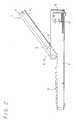
- FIG. 2 shows a schematic view showing a side surface of the laptop type personal computer shown in FIG. 1.
- a conductive material 5 is provided between the rotary portions 9 and 10 of the lower panel 4 of the open/close-type panel 1, and a conductive material (cushion 6) is provided at a position of the main body 2 corresponding to the conductive material 5.
- a conductive material (cushion 6) is provided at a position of the main body 2 corresponding to the conductive material 5.
- the conductive material 5 is connected to a conductive surface for preventing an undesired radiation provided inside the lower panel 4 and an upper panel 3, and the cushion 6 is connected with a conductive surface for preventing an undesired radiation provided inside the main body 2. Further, the conductive surface of the main body 2 is connected with a zero electric potential portion (earth line) 13 to be connected with a power source 12 in the main body 2.
- the conductive material 5 and the cushion 6 are connected with each other face to face, the conductive surface for preventing an undesired radiation inside the open/close-type panel 1 is connected with the zero electric potential portion in the main body 2 by a low impedance. As a result, an electromagnetic noise radiated from the open/close-type panel 1 is reduced.
- an illustrative electronic appliance having the open/close-type panel and an illustrative method for reducing an electromagnetic noise radiated from the open/close-type panel according to the present invention will b explained in detail.
- FIG. 3 shows an outer appearance of the lower panel 4 of the open/close-type panel 1.
- a metal material such as magnesium alloy and so on, or a synthetic resin material is used.
- the shape of the lower panel 4 is the same even if either material is used.
- An ornamental surface (painted surface) 14 is an outside surface of the lower panel 4, that is, a surface which can be seen from an outside and is painted so that its outer appearance is enhanced. Because this ornamental surface (painted surface) 14 is coated with a paint, it has no electrical conductivity.
- a rear surface (masked surface) 15 of the ornamental surface 14 is a surface inside the lower panel 4, which cannot be seen from the outside, that is, a surface corresponding to a rear surface of the ornamental surface (painted surface) 14.
- This rear surface (masked surface) 15 of the ornamental surface does not need an enhancement of its ornamental for the outer appearance and is coated with masking when the ornamental surface (painted surface) 14 is painted with a view to generating electrical conductivity so that a coating material does not adhere.
- the rear surface (masked surface) 15 of the ornamental surface has the electric conductivity due to the masking applied at the time of painting in comparison with the ornamental surface (painted surface) 14.
- This rear surface (masked surface) 15 of the ornamental surface is the conductive surface for preventing an undesired radiation.
- connection-use column 16 fixes the lower panel 4 and the upper panel 3 integrally so as to electrically connect them. Columns which are similar to the connection column 16 are provided at corresponding positions of to the upper panel 3, and the columns are fixed by screws.
- connection columns 16 the electrical connection between the lower panel 4 and the upper panel 3 is secured by not only the connection columns 16 but also intermesh of stepped portions (not shown) provided on edges of the lower panel 4 and the upper panel 3.
- a conductive material fixing portion 17 is a portion on the lower panel 4 side, which corresponds to the contact portion 11 where the open/close-type panel comes in contact with the main body 2 and is positioned between the rotary portions 9 and 10. A conductive material, mentioned later, is fixed on this portion.
- the ornamental surface 14 shows a ground surface of the synthetic resin material or is painted, and thus, needless to say, it has no electrical conductivity.
- the rear surface 15 of the ornamental surface is wholly coated with a conductive coating material, and it is used as the conductive surface for preventing an undesired radiation.
- the ornamental surface 14 is masked so that the conductive coating material does not adhere to the ornamental surface 14.
- FIG. 4 is a cross-sectional view showing the conductive material fixing portion 17 of the lower panel 4 viewed from a direction A shown in FIG. 3.
- FIG. 4 shows the case where the metal material is used for the lower panel 4, and the case where a conductive tape 18, which functions also as a connection member for electrically connecting the conductive material 5 with the conductive surface, is used as the conductive material 5.
- the conductive tape 18 is bonded on the ornamental surface (painted surface) 14 through the rear surface (masked surface) 15 of the ornamental surface including an end surface of the lower panel 4, and a common tape having conductivity (for example, trade name: CHO ⁇ EFOIL manufactured by Taiyo Metal Net Co. Ltd) can be used.
- a common tape having conductivity for example, trade name: CHO ⁇ EFOIL manufactured by Taiyo Metal Net Co. Ltd
- This conductive tape 18 has organic materials such as plastic and the like as its base material, and conductivity is given to the tape itself by blending the base material with a conductive substance and the like.
- the conductive tape 18 is bonded by being folded at the end surface of the lower panel 4, it is required to have flexibility.
- this conductive tape 18 is made of the organic materials such as plastic and the like, it has flexibility against a bend and even when it is bent at an acute angle, the conductive tape 18 itself never breaks and becomes fatigued.
- a surface on one side of the conductive tape 18 (in FIG. 4, a surface of the conductive tape 18, which comes in contact with the ornamental surface (painted surface) 14 and the rear surface (masked surface) 15 of the ornamental surface), is a bonding surface and an adhesive is coated on this bonding surface.
- This adhesive has conductivity. That is, a conductive adhesive is coated on the bonding surface of the conductive tape 18. Therefore, when the conductive tape 18 is bonded on a body having conductivity, the body and the base material of the conductive tape 18 are electrically connected through the conductive adhesive.
- a surface (in FIG. 4, a surface of the conductive tape 18 not in contact with the lower panel 4) on the other side of the conductive tape 18 comes to be brought into conduction with the bonding surface because, as mentioned above, the base material itself of the conductive tape 18 has the conductivity. Therefore, in the conductive tape 18, the surface on a bonding surface side and the surface on an opposite side of the bonding surface come to have the conductivity spanning the both surfaces.
- the conductive tape 18 is bonded on the lower panel 4 from the inside to the outside thereof.
- the conductive tape 18 is bonded on the lower panel 4 from the rear surface (masked surface) 15 of the ornamental surface to the ornamental surface (painted surface) 14.
- the conductive tape 18 is bonded on the surface (conductive surface) which is applied with masking and has the conductivity. Meanwhile, in the ornamental surface (painted surface) 14, the conductive tape 18 is bonded within a range of being able to sufficiently cover a lower part of the ornamental surface (painted surface) 14, that is, a portion of the ornamental surface (painted surface) 14, which is in contact with the main body 2.
- the conductive tape 18 is bonded on the rear surface (masked surface) 15 of the ornamental surface of the lower panel 4, and the conductive tape 18 is folded at the end of the lower panel 4 so as to be bonded also on the conductive material fixing portion 17.
- the conductive material 5 which conducts the conductive surface for preventing an undesired radiation of the open/close-type panel 1 is easily formed on a portion (conductive material fixing portion 17) where the open/close-type panel 1 comes in contact with the main body 2.
- masking is also applied on a rear surface side of the upper panel 3 of the open/close-type panel 1 at the time of coating so that a conductive surface is formed thereon, and as mentioned above, both the conductive surfaces on rear surface sides of the ornamental surfaces of the upper panel 3 and the lower panel 4 come in contact with each other, that is, the conductive surface of the upper panel 3 has conductivity with the conductive surface of the lower panel 4. As a result, the conductive surface which was formed so as to cover the whole part of the open/close-type panel 1 is connected with the conductive material 5.
- the conductive material such as the conductive tape 18 having the flexibility against a bend which also has a function to connect the conductive material 5 and the conductive surface, even when the shape of the lower panel 4 has an complex curved surface and the conductive material has to be bent at the end surface of the lower panel 4, the conductive material can be bonded along the shape of the surface of the lower panel 4 without mechanically destroying the conductive material and subjecting it to fatigue. Therefore, this conductive material can firmly be fixed to the lower panel 4.
- the conductive tape 18 which is the same as the example of FIG. 4 can be used as the conductive material 5.
- the conductive material 5 which conducts the conductive surface for an undesired radiation of the open/ close-type panel 1 can be easily formed on the portion ( conductive material fixing portion 17) where the open/close-type panel 1 comes in contact with the main body 2 by the simple work in the completely same manner as the example of FIG. 4.
- a metal plate 19 such as an aluminum plate shown in FIG. 5 can be used as the conductive material 5 to be formed on the open/close-type panel 1.
- a cross section of the metal plate 19 has an arc shape to be along the curved surface of the conductive material fixing portion 17 of the lower panel 4.
- FIGS. 6 and 7 show a method of mounting the metal plate 19 to the lower panel 4.
- the metal plate 19 is fixed to the lower panel 4 by using plural metal screws 20.
- the conductive surface for preventing an undesired radiation of the lower panel 4 is connected with the conductive material 5 (metal plate 19) via the metal screws 20.
- the metal plate 19 is fixed to the lower panel 4 by using a conductive adhesive 21.
- Plural apertures 22 are provided in the contact portion 11 of the lower panel 4.
- the conductive adhesive 21 is coated on the metal plate 19 through the apertures 22 from the conductive surface side of the lower panel 4.
- the conductive surface for preventing an undesired radiation of the lower panel 4 is connected with the conductive material 5 (metal plate 19) via the conductive adhesive 21.
- FIG. 8 shows the state that the cushion 6 is fixed to the main body 2 made of a metal material.
- a side of the main body 2 to which the cushion 6 (mentioned later) is fixed is a coated surface, and masking is applied thereon at a time of paining. That is, a metal material is exposed from a surface of the main body 2 on which the cushion 6 is bonded and this surface has conductivity.
- the cushion 6 (conductive material) is made of an organic material such as rubber or the like, and the organic material is blended with a conductive substance such as carbon and the like.
- a basic material itself of the cushion 6 has the conductivity.
- One surface of the cushion 6, that is, a surface on the side coming in contact with the main body 2 is coated with a conductive adhesive 23. As a result, the cushion 6 conducts with the conductive surface for preventing an undesired radiation of the main body 2.
- FIG. 9 shows the state that the cushion 6 is fixed to a masked portion (metal material exposed portion formed by applying the masking thereto at the time of paining) 24 of the main body 2.
- an outer periphery of the masked portion 24 comes to a more inner side than an outer periphery of the cushion 6 so that the metal material of the masked portion 24 is not seen directly.
- FIG. 10 there exists a method shown in FIG. 10 as another method of fixing the cushion 6 to the masked portion 24 of the main body.
- both ends of the cushion 6 are fixed to the masked portion 24 by a non-conductive adhesive 25, and a center portion of the cushion material 6 is directly in contact with the metal material of the masked portion 24.
- the open/close-type panel 1 comes in contact with the main body 2, and a portion of the cushion 6 other than both the ends of the cushion 6 is pressed against the exposed metal portion of the masked portion 24, thereby obtaining the firm connection.
- the above refers to the case where the main body 2 is made of a metal material, but in the case where the main body 2 is made of a synthetic resin material similarly to the above-mentioned upper panel 3 and lower panel 4 of the open/close-type panel 1, the cushion 6 is fixed to the main body 2 in the following manner.
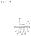
- FIG. 11 shows the state that the cushion 6 is fixed to the main body 2 made of the synthetic resin material.
- An ornamental surface 26 of the main body 2 exposes the ground itself of the synthetic resin material or is coated with paining, and thus, needless to say, has no electrical conductivity.
- a rear surface 27 of the ornamental surface is coated with a conductive compound on its whole surface, and this becomes the conductive surface for preventing an undesired radiation.
- the cushion 6 is bonded on the ornamental surface 26 of the main body 2 through the conductive adhesive 23.
- Plural apertures 28 are provided on a whole surface of a portion of the main body 2 on which the cushion 6 is bonded.
- a conductive adhesive 29 is charged into the apertures 28 from the rear surface 27 side of the ornamental surface of the main body 2. As a result, the cushion 6 conducts the conductive surface for preventing an undesired radiation of the main body 2.
- the cushion 6 has not only the conductivity but also plays, at a time of the open/close-type panel 1 being opened until it comes in contact with the main body 2, a role as a shock absorbing material least that the lower panel 4 bumps hard against the main body 2 thereby damaging the surface of the lower panel 4 or the main body 2. That is, the cushion 6 has the role as a pad (stopper) for the open/close-type panel 1. Therefore, it becomes necessary for the cushion 6 (conductive material) to have elasticity.
- the conductive material bonded on the main body 2 is not limited to the cushion 6, but other materials can naturally be used so long as they have the conductivity and the elasticity.
- the portion of the main body 2, on which masking is applied, and the portion thereof which comes in contact with the lower panel 4 are given conductivity.
- the open-close-type panel 1 when the open-close-type panel 1 is opened until it comes in contact with the main body 2 while being in use, even if a strong force is exerted to have the open/close-type panel 1 collide with the main body 2, the open/close-type panel 1 and the main body 2 can be prevented from being damaged as well as the conductive material or tape 5 bonded on the lower panel 4 can be prevented from being damaged.
- a contacting area of the conductive material on the main body side and the conductive tape 5 of the lower panel 4 can be made larger than a case in which the conductive material on the main body side doesn't have the elasticity.
- the upper panel 3 and the lower panel 4 are brought into conduction through the conductive surfaces provided respectively thereon, and of the rear surface (conductive surface) 15 of the ornamental surface of the lower panel 4 and the portion of the ornamental surface (painted surface) 14 of the lower panel 4, a portion which is in contact with the main body 2 is brought into conduction thereto through the conductive material 5, and the conductive material 5 and the cushion 6 are brought into conduction, and further this cushion 6 is brought into conduction with the conductive surface of the main body 2 and the conductive surface is brought into conduction with the zero electric potential portion 13.
- the conductive surface of the upper panel 3 and the conductive surface of the lower panel 4 are in contact with each other face to face; the conductive surface 15 of the lower panel 4 and the conductive material 5 are bonded face to face; the conductive cross-sectional area of the conductive material 5 can be secured large since the width of the conductive material 5 can be secured wide; the conductive material 5 and the cushion 6 are in contact with each other face to face, and further selection of a material having appropriate elasticity for the cushion 6 makes it possible to further enlarge a contacting area due to a recess being formed in the cushion 6; since the width of the cushion 6 can be widened and also, its thickness is thin to present small resistance, it is possible to obtain a sufficient conductivity; and because sufficient conductivity can be secured as the cushion 6 and the conductive surface of the main body 2 can be bonded face to face, the open/close-type panel 1 and the main body 2 are brought into conduction while securing a wide conductive area.
- the electromagnetic noise which is generated in the open/close-type panel is connected with the zero electric potential portion (earth line) of the main body 2 through a wide surface, the electromagnetic noise radiated outside from the open/close-type panel can be reduced by a large margin so that an effective measure can be employed against the undesired radiation from the open/close-type panel.
- the present invention is not limited to the above-mentioned embodiment, and other various kinds of compositions can be employed without departing from the gist of the present invention.
- the open/close-type panel has the conductive material which electrically conducts the portion being in contact with the main body and the conductive surface for preventing an undesired radiation
- the main body has the conductive material having elasticity which electrically conducts the portion being in contact with the open/close-type panel and the zero electric potential portion (earth line), and by opening the open/close-type panel until it comes in contact with the main body at a time of being in use, the conductive material provided in the open/close-type panel and the conductive material provided in the main body are brought into contact with each other face to face by an elastic deformation, the electromagnetic noise which occurs in the open/close-type panel is grounded to the main body through a wide surface so that electromagnetic noise radiated outside from the open/close-type panel can be reduced by a large margin.
- the conductive material provided on the open/close-type panel has the elasticity against a bend, even when the conductive material has to be bent, it never happens that the conductive material is mechanically destroyed and fatigued. Also, because the conductive material provided on the main body has the elasticity, the contacting area between the conductive material on the main body side and the conductive material of the lower panel can be made larger.
Landscapes
- Engineering & Computer Science (AREA)
- Theoretical Computer Science (AREA)
- Computer Hardware Design (AREA)
- Physics & Mathematics (AREA)
- General Engineering & Computer Science (AREA)
- Human Computer Interaction (AREA)
- General Physics & Mathematics (AREA)
- Electromagnetism (AREA)
- Power Engineering (AREA)
- Mathematical Physics (AREA)
- Shielding Devices Or Components To Electric Or Magnetic Fields (AREA)
Applications Claiming Priority (2)
| Application Number | Priority Date | Filing Date | Title |
|---|---|---|---|
| JP320098 | 1998-01-09 | ||
| JP320098 | 1998-01-09 |
Publications (1)
| Publication Number | Publication Date |
|---|---|
| EP0929026A2 true EP0929026A2 (de) | 1999-07-14 |
Family
ID=11550797
Family Applications (1)
| Application Number | Title | Priority Date | Filing Date |
|---|---|---|---|
| EP99300115A Withdrawn EP0929026A2 (de) | 1998-01-09 | 1999-01-07 | Elektronisches Gerät mit reduzierter elektromagnetischer Störung |
Country Status (5)
| Country | Link |
|---|---|
| US (1) | US6414840B2 (de) |
| EP (1) | EP0929026A2 (de) |
| KR (1) | KR19990067767A (de) |
| SG (1) | SG71896A1 (de) |
| TW (1) | TW409232B (de) |
Cited By (1)
| Publication number | Priority date | Publication date | Assignee | Title |
|---|---|---|---|---|
| DE19948092A1 (de) * | 1999-10-06 | 2001-04-12 | Siemens Pc Systeme Gmbh & Co K | PC mit EMV-Kontaktierung zwischen Gehäuse und Steckeranschlussfeld |
Families Citing this family (14)
| Publication number | Priority date | Publication date | Assignee | Title |
|---|---|---|---|---|
| KR100413601B1 (ko) * | 2001-03-08 | 2003-12-31 | 엘지전자 주식회사 | 폴더가 구비된 이동 단말기 |
| US7158373B2 (en) * | 2004-03-08 | 2007-01-02 | Originatic Llc | Electronic device having a keyboard rotatable about an axis |
| US20070247800A1 (en) * | 2004-03-08 | 2007-10-25 | Originatic Llc | Assembly having a main unit and a mounting unit |
| US8934226B2 (en) | 2004-03-08 | 2015-01-13 | Originatic Llc | Mountable device having a pivotable input device support |
| US7826205B2 (en) * | 2004-03-08 | 2010-11-02 | Originatic Llc | Electronic device having a movable input assembly with multiple input sides |
| USD611046S1 (en) | 2007-04-17 | 2010-03-02 | Originatic Llc | Electronic device |
| JP4786611B2 (ja) * | 2007-08-09 | 2011-10-05 | 富士通株式会社 | 電子機器 |
| USD606536S1 (en) | 2008-01-03 | 2009-12-22 | Originatic Llc | Electronic device |
| USD611047S1 (en) | 2008-01-03 | 2010-03-02 | Originatic Llc | Electronic device |
| US20090174992A1 (en) * | 2008-01-09 | 2009-07-09 | Eric Simon | System and Method for Supporting Electrical Connectivity Between Information Handling System Chassis Components |
| USD614181S1 (en) | 2008-05-22 | 2010-04-20 | Originatic Llc | Electronic device |
| CN102907019B (zh) | 2010-07-29 | 2015-07-01 | 英派尔科技开发有限公司 | 通过控制电子设备操作的声学噪声管理 |
| US20150171504A1 (en) * | 2013-12-13 | 2015-06-18 | Kabushiki Kaisha Toshiba | Electronic apparatus |
| US10324497B1 (en) * | 2018-03-30 | 2019-06-18 | Lenovo (Singapore) Pte. Ltd. | Tiered computing device |
Family Cites Families (3)
| Publication number | Priority date | Publication date | Assignee | Title |
|---|---|---|---|---|
| JP2663591B2 (ja) | 1988-12-12 | 1997-10-15 | 日本電気株式会社 | 回転部の接続構造 |
| JPH03144818A (ja) * | 1989-10-31 | 1991-06-20 | Toshiba Corp | 携帯型電子機器 |
| KR0181115B1 (ko) | 1993-12-30 | 1999-05-15 | 김광호 | 공통선 신호장치의 아이에스디엔 사용자부와 메세지 전달부사이의 정합 회로 |
-
1998
- 1998-12-30 TW TW087121909A patent/TW409232B/zh not_active IP Right Cessation
- 1998-12-31 SG SG1998005989A patent/SG71896A1/en unknown
-
1999
- 1999-01-06 US US09/225,943 patent/US6414840B2/en not_active Expired - Fee Related
- 1999-01-07 EP EP99300115A patent/EP0929026A2/de not_active Withdrawn
- 1999-01-07 KR KR1019990000149A patent/KR19990067767A/ko not_active Withdrawn
Cited By (2)
| Publication number | Priority date | Publication date | Assignee | Title |
|---|---|---|---|---|
| DE19948092A1 (de) * | 1999-10-06 | 2001-04-12 | Siemens Pc Systeme Gmbh & Co K | PC mit EMV-Kontaktierung zwischen Gehäuse und Steckeranschlussfeld |
| DE19948092B4 (de) * | 1999-10-06 | 2006-01-26 | Fujitsu Siemens Computers Gmbh | PC mit EMV-Kontaktierung zwischen Gehäuse und Steckeranschlussfeld |
Also Published As
| Publication number | Publication date |
|---|---|
| KR19990067767A (ko) | 1999-08-25 |
| US20010046114A1 (en) | 2001-11-29 |
| TW409232B (en) | 2000-10-21 |
| SG71896A1 (en) | 2000-04-18 |
| US6414840B2 (en) | 2002-07-02 |
Similar Documents
| Publication | Publication Date | Title |
|---|---|---|
| US6414840B2 (en) | Electronic appliance having open/close-type panel and method for reducing electromagnetic noise from open/close-type panel | |
| US6933929B1 (en) | Housing for a computing device | |
| TWI323639B (en) | Shield structure for information technology equipments | |
| JP6659969B2 (ja) | 端末装置 | |
| US6349043B1 (en) | Apparatus for reducing electromagnetic emissions | |
| JP2017228624A (ja) | 電子機器筐体の導通構造、およびこれを含む電子機器または映像音響機器 | |
| US5965842A (en) | Low impedance connection for an EMI containment shield including metal plating bonded to the shielded equipment through openings in a conductive ribbon | |
| JP3278388B2 (ja) | 電磁波シールド用ガスケット | |
| JPH11289185A (ja) | 開閉式パネルを有する電子機器および開閉式パネルからの電磁ノイズの軽減方法 | |
| JP2000114764A (ja) | 電子機器 | |
| JP2007165101A (ja) | 帯電防止機能を備えた電子機器 | |
| JPH0611590Y2 (ja) | 電子機器装置筐体の電磁シールド構造 | |
| JP2878153B2 (ja) | プラスチック筐体のフレームグランド強化構造 | |
| US6664464B2 (en) | EMI shielding device | |
| JPH10308590A (ja) | 電子機器 | |
| JP3026865B2 (ja) | グランディング装置 | |
| JPH0278296A (ja) | 電子機器筐体の電磁シールド装置 | |
| CN1224886A (zh) | 具有开/关型面板的电子仪器及减少其电磁噪声的方法 | |
| JPH07212074A (ja) | コネクタシールド部接触構造 | |
| US20060049490A1 (en) | Displaying apparatus | |
| KR20050028384A (ko) | 전자기기 | |
| JPH05218674A (ja) | 電磁遮蔽装置 | |
| JPH03127899A (ja) | 導電部材の筐体への取り付け構造 | |
| JPH11307979A (ja) | 機器筐体 | |
| JPH11289185A5 (ja) | 電子機器及び開閉パネルからの電磁ノイズの軽減方法 |
Legal Events
| Date | Code | Title | Description |
|---|---|---|---|
| PUAI | Public reference made under article 153(3) epc to a published international application that has entered the european phase |
Free format text: ORIGINAL CODE: 0009012 |
|
| AK | Designated contracting states |
Kind code of ref document: A2 Designated state(s): AT BE CH CY DE DK ES FI FR GB GR IE IT LI LU MC NL PT SE |
|
| AX | Request for extension of the european patent |
Free format text: AL;LT;LV;MK;RO;SI |
|
| STAA | Information on the status of an ep patent application or granted ep patent |
Free format text: STATUS: THE APPLICATION HAS BEEN WITHDRAWN |
|
| 18W | Application withdrawn |
Withdrawal date: 20021010 |