EP0929164A1 - Verfahren und Vorrichtung zur Festlegung eines Arbeitspunktes eines nichtlinearen Verstärkers in einem Übertragungskanal - Google Patents
Verfahren und Vorrichtung zur Festlegung eines Arbeitspunktes eines nichtlinearen Verstärkers in einem Übertragungskanal Download PDFInfo
- Publication number
- EP0929164A1 EP0929164A1 EP97122420A EP97122420A EP0929164A1 EP 0929164 A1 EP0929164 A1 EP 0929164A1 EP 97122420 A EP97122420 A EP 97122420A EP 97122420 A EP97122420 A EP 97122420A EP 0929164 A1 EP0929164 A1 EP 0929164A1
- Authority
- EP
- European Patent Office
- Prior art keywords
- signal
- communication channel
- linear amplifier
- pseudo noise
- level
- Prior art date
- Legal status (The legal status is an assumption and is not a legal conclusion. Google has not performed a legal analysis and makes no representation as to the accuracy of the status listed.)
- Granted
Links
- 238000004891 communication Methods 0.000 title claims abstract description 87
- 238000000034 method Methods 0.000 title claims description 26
- 238000012546 transfer Methods 0.000 claims description 29
- 230000003111 delayed effect Effects 0.000 claims description 5
- 230000000875 corresponding effect Effects 0.000 description 23
- 238000012360 testing method Methods 0.000 description 9
- 238000011088 calibration curve Methods 0.000 description 5
- 238000010586 diagram Methods 0.000 description 5
- 238000005259 measurement Methods 0.000 description 5
- 238000012544 monitoring process Methods 0.000 description 4
- 230000032683 aging Effects 0.000 description 3
- 238000007796 conventional method Methods 0.000 description 3
- 230000002596 correlated effect Effects 0.000 description 2
- 230000004907 flux Effects 0.000 description 2
- 230000002238 attenuated effect Effects 0.000 description 1
- 238000005311 autocorrelation function Methods 0.000 description 1
- 238000006243 chemical reaction Methods 0.000 description 1
- 230000003247 decreasing effect Effects 0.000 description 1
- 230000006866 deterioration Effects 0.000 description 1
- 230000000694 effects Effects 0.000 description 1
- 238000001914 filtration Methods 0.000 description 1
- 238000012423 maintenance Methods 0.000 description 1
- 238000000691 measurement method Methods 0.000 description 1
- 238000000926 separation method Methods 0.000 description 1
- 238000012795 verification Methods 0.000 description 1
Images



Classifications
-
- H—ELECTRICITY
- H04—ELECTRIC COMMUNICATION TECHNIQUE
- H04B—TRANSMISSION
- H04B7/00—Radio transmission systems, i.e. using radiation field
- H04B7/14—Relay systems
- H04B7/15—Active relay systems
- H04B7/185—Space-based or airborne stations; Stations for satellite systems
-
- H—ELECTRICITY
- H04—ELECTRIC COMMUNICATION TECHNIQUE
- H04B—TRANSMISSION
- H04B17/00—Monitoring; Testing
- H04B17/20—Monitoring; Testing of receivers
- H04B17/24—Monitoring; Testing of receivers with feedback of measurements to the transmitter
-
- H—ELECTRICITY
- H04—ELECTRIC COMMUNICATION TECHNIQUE
- H04B—TRANSMISSION
- H04B17/00—Monitoring; Testing
- H04B17/10—Monitoring; Testing of transmitters
Definitions
- This invention relates to a method and an apparatus for determining an operating point of a non-linear amplifier of a communication channel, especially a transponder in a communication satellite under load.
- a non-linear high power amplifier In high frequency communication channels, a non-linear high power amplifier must often be driven at its saturation point in order to obtain the maximum possible output.
- a signal from an uplink station on the ground is received by an antenna, converted in frequency, filtered in an input multiplexer, and amplified by a driver limiter amplifier and a high power amplifier before being filtered in the output multiplexer and retransmitted to the ground.
- the high power amplifier In order to provide a sufficient signal everywhere within the satellite footprint, the high power amplifier must be driven in its saturation point, i.e. the point of maximum in the non-linear transfer curve representing output power vs. input power, as for example shown in Fig. 6a.
- the driver limiter amplifier is a preamplifier and can be set to run in one of two modes. In linear mode, it acts as a simple linear amplifier. In limiting mode, it provides the function of an automatic level control (ALC). The DLA is normally operated in limiting mode in order to compensate short term level variations due to weather influences. In limiting mode, the DLA shall always provide the same output power to the high power amplifier (HPA), such that the HPA is permanently operated in saturation.
- HPA high power amplifier
- the HPA is always operated in saturation and that the signal power from the uplink station is high enough in level at the satellite.
- the satellite operator is forced to monitor regularly the power flux density as received at the satellite transponder input.
- the aim is that the video signal from the uplink station is strong enough so that under clear weather conditions, the HPA on board of the satellite is driven in saturation with the DLA in linear mode. This criterion must also be met if the HPA transfer curve has changed due to ageing.
- the uplink power is not accurately known (for instance if the uplink is not done from a site belonging to the satellite operator itself), the operating point of the high power amplifier cannot be determined only from monitoring the downlink power. On one hand this is due to the fact that close to saturation, the input power may vary by a few dB, while the output power will only vary at most a few tenth of dB. On the other hand, if a certain amount of downlink power is measured, it cannot be determined whether the HPA is operated below or above saturation because the transfer curve is ambiguous in output power.
- the bitrate of the telemetry data stream may contain a maximum of a few kbit/s. Therefore, even if the satellite is equipped with a power monitoring system, it is also preferable to perform measurements from a ground station instead of onboard the satellite, for many reasons (i.e. failure, weight of the satellite etc.).
- a satellite operator In addition to measuring the received power at the satellite, a satellite operator is performing regularly 'In Orbit Tests' (IOT) in order to measure the power flux density required to drive the HPA in saturation.
- IOT In Orbit Tests'
- a first conventional method as decribed in International Journal of Satellite Communications, Special issue on In-orbit Testing of Communications Satellites, Volume 13, Number 5, Wiley 1995 or in DE-C-33 33 418, is known as AM nulling according to which an amplitude modulated (AM) signal in the uplink is used which is swept in power until the amplitude modulation disappears completely. This point is exactly at saturation.
- a second conventional method of determining the transfer curve of the HPA consists of measuring transmit and receive power of a clean carrier, where all path attenuations have to be cancelled out. Both IOT measurement methods require that the transponder under test is not operated. In other words, the payload signal has to be switched off during the tests.
- a method for determining the operating point of a non-linear amplifier of a communication channel wherein a first signal is transmitted simultaneously with a second signal through said communication channel and said operating point of said non-linear amplifier is determined on the basis of an output signal of said communication channel corresponding to said second signal, the input power of said first signal being such that said non-linear amplifier is operated in a non-linear mode and the input power of said second signal being below the input power of said first signal.
- the level of said second signal is approx. 20 dB or more below the level of said first signal.
- said second signal is a pseudo noise modulated clean carrier signal and said output signal of said communication channel (1) corresponding to said second signal is a recovered carrier signal .
- said second signal is a clean carrier signal and wherein said output signal of said communication channel corresponding to said second signal is a narrowband filtered carrier signal .
- reference values are used together with said output signal of said communication channel corresponding to said second signal to determine the operating point of said non-linear amplifier.
- an apparatus for determining the operating point of a non-linear amplifier of a communication channel comprising means for transmitting a second signal through said communication channel simultaneously with a first signal being transmitted through said communication channel and means for determining said operating point of said non-linear amplifier on the basis of an output signal of said communication channel corresponding to said second signal, the input power of said first signal being such that said non-linear amplifier is operated in a non-linear mode and the input power of said second signal being below the input power of said first signal.
- said means for determining said operating point of said non-linear amplifier on the basis of an output signal of said communication channel corresponding to said second signal comprise means for storing reference values to be used together with said output signal of said communication channel corresponding to said second signal to determine the operating point of said non-linear amplifier.
- a first input signal is transmitted through the communication channel at a power level which drives the non-linear amplifier in a non-linear operation mode.
- a second input signal is transmitted through the communication channel simultaneously with the first input signal.
- the second input signal is transmitted at a level below the level of the first input signal. If the contribution of the second input signal to the total input of the non-linear amplifier is small, the operating point of the non-linear amplifier is determined almost only by the first input signal. Therefore, the output power corresponding to the second signal is determined most strongly by the input power of the first signal.
- the operating point of said non-linear amplifier is determined on the basis of an output signal of said communication channel corresponding to said second signal.
- the invention further provides a method for determining the operating point of a non-linear amplifier of a communication channel through which a payload signal is transmitted at a predetermined level, comprising: generating a first pseudo noise signal PN(t); modulating a clean carrier signal f(t) with said first pseudo noise signal PN(t) to generate a PN modulated clean carrier signal s(t); transmitting said PN modulated clean carrier signal s(t) simultaneously with said payload signal through said communication channel at a level below the level of said payload signal; receiving a receive signal s'(t) corresponding to said PN modulated clean carrier signal s(t) after having traveled through said communication channel; correlating said receive signal s'(t) with said first pseudo noise signal PN(t) to generate a recovered carrier signal f'(t); and determining the operating point of said non-linear amplifier of the communication channel on the basis of said clean carrier signal f(t) and said recovered carrier signal f'(t).
- the level of said PN modulated clean carrier signal s(t) is approx. 20 dB or even approx. 30 dB or more below the level of said payload signal.
- said first pseudo noise signal PN(t) is a binary pseudo noise sequence, said binary pseudo noise sequence being generated by means of a feed back shift register or a memory device in which a sequence of values of a pseudo noise signal is stored.
- Said correlating of said receive signal s'(t) and said first pseudo noise signal PN(t) can be achieved by delaying said first pseudo noise signal PN(t) and multiplying the delayed first pseudo noise signal PN(t) and said receive signal s'(t).
- a gain is determined on the basis of said clean carrier signal f(t) and said recovered carrier signal f'(t) and said gain is used to determine the input power of said payload signal.
- Reference values are used to derive from said gain the input power of said payload signal, said reference values having being pre-recorded for said non-linear amplifier and representing a gain curve or transfer curve of said non-linear amplifier over the input power of said payload signal.
- the method according to the invention is advantageously applicable if said communication channel is a transponder of a communication satellite.
- the invention furthermore provides an apparatus for determining the operating point of a non-linear amplifier of a communication channel through which a payload signal is transmitted at a predetermined level, comprising first pseudo noise signal generating means for generating a pseudo noise signal PN(t); first modulating means for modulating a clean carrier signal f(t) with said first pseudo noise signal PN(t) to generate a PN modulated clean carrier signal s(t); transmitting means for transmitting said PN modulated clean carrier signal s(t) simultaneously with said payload signal through said communication channel at a level below the level of said payload signal; receiving means for receiving a receive signal s'(t) corresponding to said PN modulated clean carrier signal s(t) after having traveled through said communication channel; and first correlating means for correlating said receive signal s'(t) with said pseudo noise signal PN(t) to generate a recovered carrier signal f'(t).
- the level of said PN modulated clean carrier signal s(t) is at least 20 dB or even at least 30 dB below the level of said payload signal.
- said first pseudo noise signal generating means (9) is a feed back shift register or a memory device in which a sequence of values of a pseudo noise signal is stored.
- a clean carrier signal f(t) is modulated with a pseudo noise signal PN(t) and transmitted through the communication channel at a level below the level of a payload signal which is transmitted via the communication channel simultaneously.
- the received signal s'(t) is correlated with the same pseudo noise signal PN(t) to obtain a recovered carrier signal f'(t).
- the power of the clean carrier signal f(t) and of the recovered carrier signal f'(t) are used to determine the gain of the signal and on the basis of reference values (calibration curves) the input power of the payload signal. Since the PN modulated clean carrier signal s(t) is transmitted at a low level, it is possible to perform measurements without switching off the payload signal, the input power of which defining the operating point of the non-linear amplifier.
- An important advantage of the method and the apparatus according to the invention is of course that the payload signal does not have to be switched off for performing the measurements. This limits considerably the downtime required for maintenance and verification of the communication channel, and thus increases availability of services.
- Fig. 1 shows a communication channel 1 comprising a non-linear amplifier 2 for amplifying the signals transmitted through the communication channel. If a total input signal I is fed to an input 3 of the communication channel 1, the signal travels through the communication channel 1, is amplified by the non-linear amplifier 2, and is output as an total output signal O at an output 4 of the communication channel 1.
- a non-linear mode of operation is effected if the input power P I of the total input signal I is high enough to operate the non-linear amplifier in the non-linear region (a) of its transfer curve.
- the goal is to drive the non-linear amplifier 2 in its saturation point as indicated by S in Fig. 2 to obtain maximum output power.
- each operating point of the non-linear amplifier in the non-linear region (a) is defined by a specific input power P I of an input signal I and a corresponding output power P O of an output signal O of the communication channel.
- the input signal provides an input power of P IS corresponding to an output power of P OS .
- a first input signal I 1 is transmitted through the communication channel 1 at a power level P I1 which drives the non-linear amplifier 2 in a non-linear operation mode.
- a second input signal i 2 is transmitted through the communication channel 1 simultaneously with the first input signal I 1 .
- the second input signal i 2 is transmitted at a level below the level of the first input signal I 1 .
- the input power P I2 of the second signal i 2 is lower than the input power P I1 of the first signal I 1 . If the contribution of the second input signal i 2 to the total input of the non-linear amplifier is small, the operating point of the non-linear amplifier is determined almost only by the first input signal.
- the output power P o2 corresponding to the second signal i 2 is determined most strongly by the input power P I1 of the first signal I 1 .
- any variation in input power of the first signal causes a variation in output power of the second signal.
- the second input signal should be some 15 to 30 dB or more, depending on the application, below the first input signal. This is indicated in the linear region (b) in Fig. 2 which shows a transfer curve B representing the output power of a small input signal plotted against the input power of a large input signal.
- the transfer curve B of the second input signal falls off much faster than the transfer curve of the first input signal so that any variation of the output power of the second input signal caused by a variation of the input power of the first input signal can be measured much easier as long as the part o 2 of the output signal O corresponding to the second input signal i 2 can be separated from the part O 1 of the output signal O corresponding to the first input signal I 1 , as indicated in Fig. 1.
- the separation of the contributions O 1 and o 2 of the first and second input signals I 1 and i 2 , respectively, in the output signal O may be achieved in several different ways.
- the first input signal I 1 is a FM or QPSK signal
- the second input signal i 2 may be a pseudo noise modulated clean carrier signal as will be explained further below in greater detail.
- the carrier signal can be recovered.
- the recovered carrier signal represents the output signal o 2 corresponding to the second input signal i 2 .
- the second input signal could be a clean carrier signal having a frequency which avoids deterioration of the second input signal by the first input signal, for example having a frequency outside the frequency band of the first input signal.
- narrowband filtering the output signal O at the frequency of the second input signal the part o 2 of the second input signal i 2 in the total output signal O can be determined.
- the operating point of the non-linear amplifier can be determined in different ways. If the input power of the first and second input signal is known the output power corresponding to these signals can be measured and a transfer curve or a gain curve, an example being shown in Fig. 6b, can be obtained. If the transfer curve or the gain curve is known, the input power of the first input signal driving the non-linear amplifier in a non-linear mode of operation can be determined by transmitting a second input signal of a known input power through the communication channel and measuring the output power corresponding to the second input signal.
- the input power of the first signal and, therefore, the operating point of the non-linear amplifier can be determined on the basis of the input power of the second input signal and the transfer curve or the gain curve (or any other representation of the above described relation between the large and the small input signal), if the second input signal is a small signal compared to the first input signal, as explained above.
- the transfer curve B of the second signal i 2 allows to determine the input power of the first signal I 1 to be P I1a without measuring the output power of the first signal at all.
- the transfer curve and the gain curve of the non-linear amplifier may change due to ageing.
- such a change of the transfer curve can be detected by determining the operating point of the non-linear amplifier on the basis of first and second input signals I 1 and i 2 the individual input powers P I1 and P I2 of which are known.
- the operating point can be determined and compared to the operating point derived on the basis of the transfer curve (or any other representation thereof).
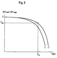
- Fig. 3 shows a diagram representing a gain difference between the first signal and the second signal, i.e. gains small - gain large , plotted over the input power of the first signal. If an operating point (P Ia , P Oa ) is determined as described above which is not on the pre-recorded curve C, ageing of the non-linear amplifier has cause a shift of the curve, indicated by curve C'. Although not shown in Fig. 2, a similar shift can also be seen in the transfer curve of the non-linear amplifier.
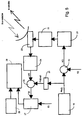
- Fig. 4 shows the components of a transponder in a communication satellite as an example for a communication channel.
- An output signal of said receiving antenna 11 is fed to an input demultiplexer (IMUX) 13 after frequency conversion in frequency converter 12.
- Said input demultiplexer 13 comprises several first filters 14-1 to 14-n for separating individual signals within the signal from the antenna. Typically, one filter is provided for each signal to be separated from the other signals received via said receiving antenna 1 and corresponds to a communication channel.
- the n output signals of said input demultiplexer 13 are fed to a corresponding number of driver limiter amplifiers 15a-1 to 15a-n and high power amplifiers 15b-1 to 15b-n.
- a travelling wave tube (TWT) is employed for amplifying the output signals of said input demultiplexer 13.
- the high power amplifiers 15b-1 to 15b-n are non-linear amplifiers having a transfer curve and gain curve as indicated by curves A in Fig. 6a and 6b, respectively. If not set to a linear mode the driver limiter amplifiers 15a-1 to 15a-n are either limiting or amplifiying the input signal received from the input demultiplexer 13 before being fed to the respective high power amplifier.
- the amplifier output signals are passed through second filters 16-1 to 16-n which are part of an output multiplexer (OMUX) 17 combining the n amplifier output signals.
- the output signal of said output multiplexer 17 is fed to a transmitting antenna 18 for being transmitted to the desired area on the ground.
- each of said high power amplifiers 15b-1 to 15b-n depends on the payload signal (the first input signal) from the uplink ground station, which signal should be such that the amplifier is driven in saturation in order to achieve maximum output power.
- the driver limiter amplifiers 15a-1 to 15a-n can be set such that each of said high power amplifiers is operated in its saturation point. For the measurement described below the driver limiter amplifiers are set to linear operation.
- a pseudo noise signal PN(t) is generated by means of a pseudo noise signal generator 19, for example a feed back shift register or a memory device in which a sequence of values of a pseudo noise signal is stored.
- the pseudo noise signal PN(t) has a very sharp autocorrelation function at zero delay. This allows to determine the time delay between the locally generated pseudo noise signal PN(t) and a received signal which is delayed due to the propagation time.
- the transponder remains usable during the test and can be continuously supplied with a payload signal.
- the level of the transmitted PN modulated clean carrier signal s(t) is sufficiently below the level of the payload signal, for example about 20 to 30 dB or more, such that the payload signal is not notably deteriorated.
- the PN modulated clean carrier signal s(t) can be transmitted while the communication channel is in use, i.e. simultaneously with a payload signal being transmitted to the transponder of the satellite from the same or from another ground station.
- antenna 23 is also used to receive the signal re-transmitted by the transponder of the satellite, in other words the signal which has traveled through the communication channel.
- the output signal of antenna 23 is passed through a downconverter 24 to obtain a receive signal s'(t) which is fed to a second multiplier 25 receiving also the same but delayed pseudo noise signal PN(t).
- the delay is generated by delaying means 26 which are set such that the output of the second multiplier 25 becomes maximum.
- the receive signal s'(t) is multiplied, in other words correlated with the very same pseudo noise signal PN(t) which has been used for generating the PN modulated clean carrier signal s(t) and a recovered carrier signal f'(t) is obtained which is only delayed and attenuated in comparison with the clean carrier signal f(t).
- the path attenuation is constant as free space loss does practically not vary with the distance between the satellite and the ground station. Since atmosperical attenuation can be measured with radiometers, it can be taken into account as well as the gain of the ground station antenna at the corresponding frequencies.
- the input power of the clean carrier signal f(t) and the output power of the recovered carrier signal f'(t) can be measured to determine the gain of this signal.
- the input power of the payload signal is determined on the basis of said gain and of reference values or calibration curves, which are shown in Fig. 6a and 6b and which will be explained in greater detail further below.
- the gain of the small signal is measured to be -4 dB the input power of the large signal is -1 dB.
- this measurement is compared to measuring the output power: while the output power of the large signal changes by less than 0.05 dB for the input power varying from 0 dBW to -1 dB, the gain of the small signal varies by almost 2 dB.
- Fig. 6a transfer curves for a large signal (A) and three small signals (B 1 , B 2 , B 3 ) over a travelling wave tube amplifier (TWTA) are shown.
- TWTA travelling wave tube amplifier
- the values are given relative to the saturation point of the amplifier.
- 0 dB input power corresponds to 0 dB output power.
- the three small signals (B 1 , B 2 , B 3 ) are 20 dB, 30 dB, and 40 dB below the large signal, respectively.
- Fig. 6b gain curves for the large signal (A) and the three small signals (B 1 , B 2 , B 3 ) are shown. Again, the values are given relative to the saturation point of the amplifier so that in Fig.
- 0 dB input power corresponds to 0 dB gain.
- the gain curves for the three small signals overlap completely.
- the above described transfer curves and gain curves, shown in Fig. 6a and 6b, are obtained as calibration curves for each amplifier in the satellite in order to determine the operating point of the individual amplifier later on.
- the calibration curves are recorded in the form of reference values which are stored in appropriate storage means for being used in determining the operating point of the non-linear amplifier.
- a large signal and a small signal are generated where the small signal is for example 20 dB, 30 dB, or 40 dB below the large signal.
- the large and the small signal may be a clean carrier or the large signal may be a FM or OPSK modulated signal to come as close as possible to real operation conditions and the small signal may be a pseudo noise modulated clean carrier signal.
- Both signals, i.e. the large and the small signal are combined and transmitted to the transponder.
- the total input signal received by antenna 11 is fed to the input of the high power amplifier (TWTA).
- TWTA high power amplifier
- the combined signal is swept in power, thus the level difference between the large signal and the small signal at the input will always remain the same.
- the power of the small signal may be kept constant as it does not substantially influence the operating point of the non-linear amplifier.
- the output signal of the high power amplifier (TWTA) is fed to antenna 18 via output demultiplexer 17 and the output levels corresponding to both input signals are measured separately.
- the output power of the large signal (which is almost equal to the total output power as the small signal has a negligible contribution) is given as a function of the input power of the large signal.
- the output power of the small signal is also given as a function of the input power of the large signal.
- the gain of the large signal and the gain of the small signals are given as a function of the input power of the large signal.
- means 27 for determining a gain on the basis of said clean carrier signal f(t) and said recovered carrier signal f'(t) are provided, receiving both the clean carrier signal f(t) and the recovered carrier signal f'(t). Furthermore, means 28 for deriving the input power of said payload signal from reference values and from said gain. The output of said means 27 for determining a gain are supplied to said means 28 for deriving the input power of said payload signal.
- the reference values are stored in and supplied from means 29 for storing said reference values. The said reference values have been pre-recorded for said non-linear amplifier and represent a gain curve or transfer curve of said non-linear amplifier over the input power of said payload signal, as described with respect to Fig. 6a and 6b.
- true noise signals can be used in the method and the apparatus according to the invention. Properties of true and pseudo noise signals are well known to those skilled in the art and are described, for example in Bernard Sklar, "Digital Communications - Fundamentals and Applications", Prentice Hall, 1988.
Landscapes
- Engineering & Computer Science (AREA)
- Physics & Mathematics (AREA)
- Computer Networks & Wireless Communication (AREA)
- Signal Processing (AREA)
- Electromagnetism (AREA)
- Astronomy & Astrophysics (AREA)
- Aviation & Aerospace Engineering (AREA)
- General Physics & Mathematics (AREA)
- Radio Relay Systems (AREA)
- Amplifiers (AREA)
- Monitoring And Testing Of Transmission In General (AREA)
- Control Of Amplification And Gain Control (AREA)
Priority Applications (23)
| Application Number | Priority Date | Filing Date | Title |
|---|---|---|---|
| AT97122420T ATE190785T1 (de) | 1997-12-18 | 1997-12-18 | Verfahren und vorrichtung zur festlegung eines arbeitspunktes eines nichtlinearen verstärkers in einem übertragungskanal |
| ES97122420T ES2145552T3 (es) | 1997-12-18 | 1997-12-18 | Procedimiento y dispositivo de determinacion de un punto de funcionamiento de un amplificador no-lineal de un canal de comunicacion. |
| EP97122420A EP0929164B1 (de) | 1997-12-18 | 1997-12-18 | Verfahren und Vorrichtung zur Festlegung eines Arbeitspunktes eines nichtlinearen Verstärkers in einem Übertragungskanal |
| DK97122420T DK0929164T3 (da) | 1997-12-18 | 1997-12-18 | Fremgangsmåde og apparat til at bestemme et arbejdspunkt for en ikke-lineær forstærker i en kommunikationskanal |
| DE69701473T DE69701473T2 (de) | 1997-12-18 | 1997-12-18 | Verfahren und Vorrichtung zur Festlegung eines Arbeitspunktes eines nichtlinearen Verstärkers in einem Übertragungskanal |
| PT97122420T PT929164E (pt) | 1997-12-18 | 1997-12-18 | Metodo e aparelho de determinacao do ponto operacional de um amplificador nao linear num canal de comunicacao |
| JP2000525993A JP3639531B2 (ja) | 1997-12-18 | 1998-12-17 | 通信チャンネルの非線形増幅器の動作点を決定する方法と装置 |
| IL13676598A IL136765A (en) | 1997-12-18 | 1998-12-17 | Method and apparatus for determining an operating point of a non-linear amplifier of a communication channel |
| KR1020007006749A KR100609315B1 (ko) | 1997-12-18 | 1998-12-17 | 통신 채널의 비선형 증폭기의 동작점을 결정하는 방법 및 장치 |
| CNB988130351A CN1136682C (zh) | 1997-12-18 | 1998-12-17 | 用于确定通信信道的非线性放大器的工作点的方法和设备 |
| IDW20001365A ID24961A (id) | 1997-12-18 | 1998-12-17 | Metode dan peralatan untuk menentukan titik operasi penguat tak lurus dari suatu saluran komunikasi |
| EA200000669A EA002214B1 (ru) | 1997-12-18 | 1998-12-17 | Способ и устройство для определения рабочей точки нелинейного усилителя канала связи |
| CA002315053A CA2315053C (en) | 1997-12-18 | 1998-12-17 | Method and apparatus for determining an operating point of a non-linear amplifier of a communication channel |
| AU25134/99A AU741481B2 (en) | 1997-12-18 | 1998-12-17 | Method and apparatus for determining an operating point of non-linear amplifier of a communication channel |
| TR2000/01780T TR200001780T2 (tr) | 1997-12-18 | 1998-12-17 | Bir iletişim kanalının linear olmayan bir operasyon noktasının belirlenmesi için cihaz ve yöntem. |
| US09/213,557 US6275678B1 (en) | 1997-12-18 | 1998-12-17 | Method and apparatus for determining an operating point of a non-linear amplifier of a communication channel |
| PCT/EP1998/008306 WO1999033203A1 (en) | 1997-12-18 | 1998-12-17 | Method and apparatus for determining an operating point of a non-linear amplifier of a communication channel |
| PL98341217A PL190186B1 (pl) | 1997-12-18 | 1998-12-17 | Sposób i urządzenie do wyznaczania punktu pracy nieliniowego wzmacniacza kanału telekomunikacyjnego |
| BRPI9813708-5A BR9813708B1 (pt) | 1997-12-18 | 1998-12-17 | processo e aparelho para determinar um ponto de operação de um amplificador não linear de um canal de comunicação. |
| ARP980106507A AR008353A1 (es) | 1997-12-18 | 1998-12-18 | Metodo y aparato para determinar un punto de funcionamiento de un amplificador alineal de un canal de comunicacion |
| HK00100189.1A HK1021455B (en) | 2000-01-12 | Method and apparatus for determining an operating point of a non-linear amplifier of a communication channel | |
| GR20000401168T GR3033472T3 (en) | 1997-12-18 | 2000-05-22 | Method and apparatus for determining an operating point of a non-linear amplifier of a communication channel |
| NO20003158A NO323273B1 (no) | 1997-12-18 | 2000-06-16 | Fremgangsmate og apparat for a bestemme et operasjonspunkt for en ulineaer forsterker i en kommunikasjonskanal |
Applications Claiming Priority (1)
| Application Number | Priority Date | Filing Date | Title |
|---|---|---|---|
| EP97122420A EP0929164B1 (de) | 1997-12-18 | 1997-12-18 | Verfahren und Vorrichtung zur Festlegung eines Arbeitspunktes eines nichtlinearen Verstärkers in einem Übertragungskanal |
Publications (2)
| Publication Number | Publication Date |
|---|---|
| EP0929164A1 true EP0929164A1 (de) | 1999-07-14 |
| EP0929164B1 EP0929164B1 (de) | 2000-03-15 |
Family
ID=8227830
Family Applications (1)
| Application Number | Title | Priority Date | Filing Date |
|---|---|---|---|
| EP97122420A Expired - Lifetime EP0929164B1 (de) | 1997-12-18 | 1997-12-18 | Verfahren und Vorrichtung zur Festlegung eines Arbeitspunktes eines nichtlinearen Verstärkers in einem Übertragungskanal |
Country Status (22)
| Country | Link |
|---|---|
| US (1) | US6275678B1 (de) |
| EP (1) | EP0929164B1 (de) |
| JP (1) | JP3639531B2 (de) |
| KR (1) | KR100609315B1 (de) |
| CN (1) | CN1136682C (de) |
| AR (1) | AR008353A1 (de) |
| AT (1) | ATE190785T1 (de) |
| AU (1) | AU741481B2 (de) |
| BR (1) | BR9813708B1 (de) |
| CA (1) | CA2315053C (de) |
| DE (1) | DE69701473T2 (de) |
| DK (1) | DK0929164T3 (de) |
| EA (1) | EA002214B1 (de) |
| ES (1) | ES2145552T3 (de) |
| GR (1) | GR3033472T3 (de) |
| ID (1) | ID24961A (de) |
| IL (1) | IL136765A (de) |
| NO (1) | NO323273B1 (de) |
| PL (1) | PL190186B1 (de) |
| PT (1) | PT929164E (de) |
| TR (1) | TR200001780T2 (de) |
| WO (1) | WO1999033203A1 (de) |
Cited By (3)
| Publication number | Priority date | Publication date | Assignee | Title |
|---|---|---|---|---|
| EP1523103A1 (de) * | 2003-10-10 | 2005-04-13 | The Directv Group, Inc. | Kohärente Mittelwertbildung zum Messen der Nichtlinearitäten eines Wanderfeldröhrenverstärkers |
| EP1563601A4 (de) * | 2002-10-25 | 2006-05-17 | Directv Group Inc | Schätzen des arbeitspunkts eines nichtlinearenausbreitungswellenrührenverstärkers |
| WO2011144620A1 (de) * | 2010-05-17 | 2011-11-24 | Inradios Integrated Radio Solutions Gmbh | Anordnung und verfahren zur parallelen verarbeitung von datenströmen mittels satellitenkommunikationsverbindungen |
Families Citing this family (31)
| Publication number | Priority date | Publication date | Assignee | Title |
|---|---|---|---|---|
| ATE215287T1 (de) * | 1997-12-18 | 2002-04-15 | Soc Europ Des Satellites Sa | Verfahren und apparat zur bestimmung der kennwerte von komponenten eines kommunikationskanals unter last |
| EA004457B1 (ru) * | 1999-06-18 | 2004-04-29 | Сосьете Эропеен Де Сателит С.А. | Способ и устройство определения характеристик компонент канала связи |
| US7778365B2 (en) | 2001-04-27 | 2010-08-17 | The Directv Group, Inc. | Satellite TWTA on-line non-linearity measurement |
| US7151807B2 (en) | 2001-04-27 | 2006-12-19 | The Directv Group, Inc. | Fast acquisition of timing and carrier frequency from received signal |
| US7184473B2 (en) | 2001-04-27 | 2007-02-27 | The Directv Group, Inc. | Equalizers for layered modulated and other signals |
| US7471735B2 (en) | 2001-04-27 | 2008-12-30 | The Directv Group, Inc. | Maximizing power and spectral efficiencies for layered and conventional modulations |
| US7209524B2 (en) | 2001-04-27 | 2007-04-24 | The Directv Group, Inc. | Layered modulation for digital signals |
| US7822154B2 (en) | 2001-04-27 | 2010-10-26 | The Directv Group, Inc. | Signal, interference and noise power measurement |
| US7245671B1 (en) | 2001-04-27 | 2007-07-17 | The Directv Group, Inc. | Preprocessing signal layers in a layered modulation digital signal system to use legacy receivers |
| US7423987B2 (en) | 2001-04-27 | 2008-09-09 | The Directv Group, Inc. | Feeder link configurations to support layered modulation for digital signals |
| US7639759B2 (en) | 2001-04-27 | 2009-12-29 | The Directv Group, Inc. | Carrier to noise ratio estimations from a received signal |
| US7502430B2 (en) | 2001-04-27 | 2009-03-10 | The Directv Group, Inc. | Coherent averaging for measuring traveling wave tube amplifier nonlinearity |
| US7184489B2 (en) | 2001-04-27 | 2007-02-27 | The Directv Group, Inc. | Optimization technique for layered modulation |
| US7483505B2 (en) | 2001-04-27 | 2009-01-27 | The Directv Group, Inc. | Unblind equalizer architecture for digital communication systems |
| US7512189B2 (en) | 2001-04-27 | 2009-03-31 | The Directv Group, Inc. | Lower complexity layered modulation signal processor |
| US7583728B2 (en) | 2002-10-25 | 2009-09-01 | The Directv Group, Inc. | Equalizers for layered modulated and other signals |
| US8005035B2 (en) | 2001-04-27 | 2011-08-23 | The Directv Group, Inc. | Online output multiplexer filter measurement |
| US7173981B1 (en) | 2001-04-27 | 2007-02-06 | The Directv Group, Inc. | Dual layer signal processing in a layered modulation digital signal system |
| KR20030024285A (ko) * | 2001-09-17 | 2003-03-26 | 한국전자통신연구원 | 위성통신 시스템에서의 고출력 증폭기 동작점 판단 장치및 그 방법 |
| WO2004004193A2 (en) | 2002-07-01 | 2004-01-08 | The Directv Group, Inc. | Improving hierarchical 8psk performance |
| ES2604453T3 (es) | 2002-07-03 | 2017-03-07 | The Directv Group, Inc. | Método y aparato para modulación en capas |
| AU2003282854A1 (en) | 2002-10-25 | 2004-05-25 | The Directv Group, Inc. | Method and apparatus for tailoring carrier power requirements according to availability in layered modulation systems |
| US7474710B2 (en) | 2002-10-25 | 2009-01-06 | The Directv Group, Inc. | Amplitude and phase matching for layered modulation reception |
| US7463676B2 (en) | 2002-10-25 | 2008-12-09 | The Directv Group, Inc. | On-line phase noise measurement for layered modulation |
| US7529312B2 (en) | 2002-10-25 | 2009-05-05 | The Directv Group, Inc. | Layered modulation for terrestrial ATSC applications |
| KR100488347B1 (ko) | 2002-10-31 | 2005-05-10 | 삼성전자주식회사 | 실록산계 수지 및 이를 이용한 반도체 층간 절연막의형성방법 |
| US7502429B2 (en) | 2003-10-10 | 2009-03-10 | The Directv Group, Inc. | Equalization for traveling wave tube amplifier nonlinearity measurements |
| US20050175119A1 (en) * | 2004-02-09 | 2005-08-11 | Worley David A. | Forward link quality link monitoring apparatus and method |
| EP2223429B1 (de) * | 2007-12-21 | 2014-11-19 | Astrium Limited | Multiportverstärker für kommunikationssatelliten |
| KR101364831B1 (ko) * | 2010-11-08 | 2014-02-20 | 한국전자통신연구원 | 텔레메트리 데이터의 통계적 분석을 이용하여 위성중계기의 상태를 감시하는 장치 및 방법 |
| CN108886412B (zh) * | 2016-01-25 | 2019-06-04 | 瓦伦斯半导体有限责任公司 | 利用已知序列的传送来指示操作点的质量的方法和通信系统 |
Citations (3)
| Publication number | Priority date | Publication date | Assignee | Title |
|---|---|---|---|---|
| DE3333418A1 (de) * | 1983-09-16 | 1985-04-04 | ANT Nachrichtentechnik GmbH, 7150 Backnang | Verfahren zum bestimmen der saettigungsleistung eines satellitenleistungsverstaerkers |
| US4896369A (en) * | 1984-12-28 | 1990-01-23 | Harris Corporation | Optimal satellite TWT power allocation process for achieving requested availability and maintaining stability in ALPC-type networks |
| JPH03139027A (ja) * | 1989-10-24 | 1991-06-13 | Fujitsu Ltd | 衛星通信における送信電力制御方式 |
Family Cites Families (13)
| Publication number | Priority date | Publication date | Assignee | Title |
|---|---|---|---|---|
| US4168398A (en) * | 1976-11-10 | 1979-09-18 | Nippon Electric Co., Ltd. | Initial acquisition signal detection system for TDMA satellite communication |
| US4637017A (en) * | 1984-05-21 | 1987-01-13 | Communications Satellite Corporation | Monitoring of input backoff in time division multiple access communication satellites |
| FR2665602A1 (fr) * | 1990-08-03 | 1992-02-07 | Europ Rech Electr Lab | Procede de protection contre le desembrouillage non autorise d'emissions de television embrouillees et dispositif de mise en óoeuvre. |
| US5455960A (en) * | 1992-01-16 | 1995-10-03 | Harris Corporation | Low-power access technique for certain satellite transponders |
| EP0721166A1 (de) * | 1995-01-03 | 1996-07-10 | International Business Machines Corporation | Verfahren und System zur Entwurfsprüfung von logischen Einheiten und zur Verwendung in verschiedenen Umgebungen |
| US5635870A (en) * | 1995-08-15 | 1997-06-03 | David; Michael | Efficient amplification techniques for non-linear amplifiers |
| US5745839A (en) * | 1995-09-01 | 1998-04-28 | Cd Radio, Inc. | Satellite multiple access system with distortion cancellation and compression compensation |
| US5623227A (en) * | 1995-10-17 | 1997-04-22 | Motorola, Inc. | Amplifier circuit and method of controlling an amplifier for use in a radio frequency communication system |
| SE510569C2 (sv) * | 1996-05-31 | 1999-06-07 | Allgon Ab | Repeterare med variabel bandbredd |
| JP2806890B2 (ja) * | 1996-06-27 | 1998-09-30 | 静岡日本電気株式会社 | 無線選択呼出受信機 |
| JPH1022756A (ja) * | 1996-07-04 | 1998-01-23 | Mitsubishi Electric Corp | 無線送信機およびその送信制御方法 |
| US5731993A (en) * | 1996-09-09 | 1998-03-24 | Hughes Electronics | Nonlinear amplifier operating point determination system and method |
| US5940025A (en) * | 1997-09-15 | 1999-08-17 | Raytheon Company | Noise cancellation method and apparatus |
-
1997
- 1997-12-18 PT PT97122420T patent/PT929164E/pt unknown
- 1997-12-18 DE DE69701473T patent/DE69701473T2/de not_active Expired - Lifetime
- 1997-12-18 AT AT97122420T patent/ATE190785T1/de active
- 1997-12-18 EP EP97122420A patent/EP0929164B1/de not_active Expired - Lifetime
- 1997-12-18 ES ES97122420T patent/ES2145552T3/es not_active Expired - Lifetime
- 1997-12-18 DK DK97122420T patent/DK0929164T3/da active
-
1998
- 1998-12-17 KR KR1020007006749A patent/KR100609315B1/ko not_active Expired - Lifetime
- 1998-12-17 PL PL98341217A patent/PL190186B1/pl unknown
- 1998-12-17 BR BRPI9813708-5A patent/BR9813708B1/pt not_active IP Right Cessation
- 1998-12-17 US US09/213,557 patent/US6275678B1/en not_active Expired - Lifetime
- 1998-12-17 ID IDW20001365A patent/ID24961A/id unknown
- 1998-12-17 CA CA002315053A patent/CA2315053C/en not_active Expired - Lifetime
- 1998-12-17 AU AU25134/99A patent/AU741481B2/en not_active Expired
- 1998-12-17 TR TR2000/01780T patent/TR200001780T2/xx unknown
- 1998-12-17 WO PCT/EP1998/008306 patent/WO1999033203A1/en not_active Ceased
- 1998-12-17 JP JP2000525993A patent/JP3639531B2/ja not_active Expired - Lifetime
- 1998-12-17 CN CNB988130351A patent/CN1136682C/zh not_active Expired - Lifetime
- 1998-12-17 EA EA200000669A patent/EA002214B1/ru not_active IP Right Cessation
- 1998-12-17 IL IL13676598A patent/IL136765A/xx not_active IP Right Cessation
- 1998-12-18 AR ARP980106507A patent/AR008353A1/es active IP Right Grant
-
2000
- 2000-05-22 GR GR20000401168T patent/GR3033472T3/el unknown
- 2000-06-16 NO NO20003158A patent/NO323273B1/no not_active IP Right Cessation
Patent Citations (3)
| Publication number | Priority date | Publication date | Assignee | Title |
|---|---|---|---|---|
| DE3333418A1 (de) * | 1983-09-16 | 1985-04-04 | ANT Nachrichtentechnik GmbH, 7150 Backnang | Verfahren zum bestimmen der saettigungsleistung eines satellitenleistungsverstaerkers |
| US4896369A (en) * | 1984-12-28 | 1990-01-23 | Harris Corporation | Optimal satellite TWT power allocation process for achieving requested availability and maintaining stability in ALPC-type networks |
| JPH03139027A (ja) * | 1989-10-24 | 1991-06-13 | Fujitsu Ltd | 衛星通信における送信電力制御方式 |
Non-Patent Citations (1)
| Title |
|---|
| PATENT ABSTRACTS OF JAPAN vol. 015, no. 355 (E - 1109) 9 September 1991 (1991-09-09) * |
Cited By (6)
| Publication number | Priority date | Publication date | Assignee | Title |
|---|---|---|---|---|
| EP1563601A4 (de) * | 2002-10-25 | 2006-05-17 | Directv Group Inc | Schätzen des arbeitspunkts eines nichtlinearenausbreitungswellenrührenverstärkers |
| EP1523103A1 (de) * | 2003-10-10 | 2005-04-13 | The Directv Group, Inc. | Kohärente Mittelwertbildung zum Messen der Nichtlinearitäten eines Wanderfeldröhrenverstärkers |
| KR100778220B1 (ko) * | 2003-10-10 | 2007-11-20 | 더 디렉티브 그룹, 인크. | 트래블링 웨이브 튜브 증폭기 비선형성을 측정하기 위한가간섭성 평균화 |
| WO2011144620A1 (de) * | 2010-05-17 | 2011-11-24 | Inradios Integrated Radio Solutions Gmbh | Anordnung und verfahren zur parallelen verarbeitung von datenströmen mittels satellitenkommunikationsverbindungen |
| EP2660996A1 (de) * | 2010-05-17 | 2013-11-06 | INRADIOS Integrated radio solutions GmbH | Anordnung und Verfahren zum Test einer Satellitenkommunikationsverbindung |
| US8767805B2 (en) | 2010-05-17 | 2014-07-01 | Inradios Integrated Radio Solutions Gmbh | Assembly and method for the parallel processing of data streams by means of satellite communication links |
Also Published As
Similar Documents
| Publication | Publication Date | Title |
|---|---|---|
| EP0929164B1 (de) | Verfahren und Vorrichtung zur Festlegung eines Arbeitspunktes eines nichtlinearen Verstärkers in einem Übertragungskanal | |
| JP4197869B2 (ja) | 通信チャネルの機器の特性を決定するための方法及び装置 | |
| US5731993A (en) | Nonlinear amplifier operating point determination system and method | |
| CN1327637C (zh) | 用于确定在欠载下的通信信道的部件特性的方法和设备 | |
| JP6199127B2 (ja) | 軌道上の衛星の送信アンテナを特徴付ける方法および関連システム | |
| EP0519487B1 (de) | Verfahren und Einrichtung zur Steuerung der Sendeleistung bei der Satellitenkommunikation | |
| HK1021455B (en) | Method and apparatus for determining an operating point of a non-linear amplifier of a communication channel | |
| JPH02280424A (ja) | 送信電力制御方式 | |
| CZ20002191A3 (cs) | Způsob a zařízení pro určování pracovního bodu nelineárního zesilovače komunikačního kanálu | |
| HK1062236B (en) | Method and apparatus for determining characteristics of components of a communication channel under load | |
| KR20050097828A (ko) | 위성통신 시스템에서의 고출력 증폭기 동작점 실시간 판단장치 및 그 방법 | |
| HK1023237B (en) | Method and apparatus for determining characteristics of components of a communication channel under load | |
| JPH11234185A (ja) | 地球局および衛星搭載機器の校正装置 | |
| CZ20002192A3 (cs) | Způsob a zařízení pro určování vlastností prvků komunikačního zařízení pod zatížením |
Legal Events
| Date | Code | Title | Description |
|---|---|---|---|
| GRAG | Despatch of communication of intention to grant |
Free format text: ORIGINAL CODE: EPIDOS AGRA |
|
| PUAI | Public reference made under article 153(3) epc to a published international application that has entered the european phase |
Free format text: ORIGINAL CODE: 0009012 |
|
| 17P | Request for examination filed |
Effective date: 19980717 |
|
| AK | Designated contracting states |
Kind code of ref document: A1 Designated state(s): AT BE CH DE DK ES FI FR GB GR IE IT LI LU MC NL PT SE |
|
| AX | Request for extension of the european patent |
Free format text: AL;LT;LV;MK;RO;SI |
|
| GRAG | Despatch of communication of intention to grant |
Free format text: ORIGINAL CODE: EPIDOS AGRA |
|
| GRAH | Despatch of communication of intention to grant a patent |
Free format text: ORIGINAL CODE: EPIDOS IGRA |
|
| GRAH | Despatch of communication of intention to grant a patent |
Free format text: ORIGINAL CODE: EPIDOS IGRA |
|
| GRAA | (expected) grant |
Free format text: ORIGINAL CODE: 0009210 |
|
| AK | Designated contracting states |
Kind code of ref document: B1 Designated state(s): AT BE CH DE DK ES FI FR GB GR IE IT LI LU MC NL PT SE |
|
| AX | Request for extension of the european patent |
Free format text: AL;LT;LV;MK;RO;SI |
|
| REF | Corresponds to: |
Ref document number: 190785 Country of ref document: AT Date of ref document: 20000415 Kind code of ref document: T |
|
| REG | Reference to a national code |
Ref country code: CH Ref legal event code: EP |
|
| AKX | Designation fees paid |
Free format text: AT BE CH DE DK ES FI FR GB GR IE IT LI LU MC NL PT SE |
|
| ITF | It: translation for a ep patent filed | ||
| REF | Corresponds to: |
Ref document number: 69701473 Country of ref document: DE Date of ref document: 20000420 |
|
| REG | Reference to a national code |
Ref country code: IE Ref legal event code: FG4D |
|
| REG | Reference to a national code |
Ref country code: CH Ref legal event code: NV Representative=s name: BUECHEL & PARTNER AG PATENTBUERO |
|
| ET | Fr: translation filed | ||
| REG | Reference to a national code |
Ref country code: PT Ref legal event code: SC4A Free format text: AVAILABILITY OF NATIONAL TRANSLATION Effective date: 20000328 |
|
| REG | Reference to a national code |
Ref country code: ES Ref legal event code: FG2A Ref document number: 2145552 Country of ref document: ES Kind code of ref document: T3 |
|
| REG | Reference to a national code |
Ref country code: DK Ref legal event code: T3 |
|
| PLBE | No opposition filed within time limit |
Free format text: ORIGINAL CODE: 0009261 |
|
| STAA | Information on the status of an ep patent application or granted ep patent |
Free format text: STATUS: NO OPPOSITION FILED WITHIN TIME LIMIT |
|
| 26N | No opposition filed | ||
| PGFP | Annual fee paid to national office [announced via postgrant information from national office to epo] |
Ref country code: MC Payment date: 20011205 Year of fee payment: 5 |
|
| REG | Reference to a national code |
Ref country code: GB Ref legal event code: IF02 |
|
| REG | Reference to a national code |
Ref country code: CH Ref legal event code: PFA Free format text: SOCIETE EUROPEENNE DES SATELLITES TRANSFER- SES ASTRA S.A. |
|
| REG | Reference to a national code |
Ref country code: PT Ref legal event code: PD4A Free format text: SES ASTRA S.A. LU Effective date: 20020830 |
|
| REG | Reference to a national code |
Ref country code: FR Ref legal event code: CD |
|
| PG25 | Lapsed in a contracting state [announced via postgrant information from national office to epo] |
Ref country code: MC Free format text: LAPSE BECAUSE OF NON-PAYMENT OF DUE FEES Effective date: 20030701 |
|
| NLT1 | Nl: modifications of names registered in virtue of documents presented to the patent office pursuant to art. 16 a, paragraph 1 |
Owner name: SES ASTRA S.A. |
|
| REG | Reference to a national code |
Ref country code: FR Ref legal event code: PLFP Year of fee payment: 19 |
|
| REG | Reference to a national code |
Ref country code: FR Ref legal event code: PLFP Year of fee payment: 20 |
|
| PGFP | Annual fee paid to national office [announced via postgrant information from national office to epo] |
Ref country code: FI Payment date: 20161215 Year of fee payment: 20 Ref country code: DE Payment date: 20161215 Year of fee payment: 20 Ref country code: NL Payment date: 20161215 Year of fee payment: 20 Ref country code: DK Payment date: 20161121 Year of fee payment: 20 Ref country code: IE Payment date: 20161026 Year of fee payment: 20 Ref country code: LU Payment date: 20161227 Year of fee payment: 20 Ref country code: CH Payment date: 20161222 Year of fee payment: 20 Ref country code: GB Payment date: 20161114 Year of fee payment: 20 |
|
| PGFP | Annual fee paid to national office [announced via postgrant information from national office to epo] |
Ref country code: GR Payment date: 20161213 Year of fee payment: 20 Ref country code: ES Payment date: 20161220 Year of fee payment: 20 Ref country code: IT Payment date: 20161220 Year of fee payment: 20 Ref country code: SE Payment date: 20161118 Year of fee payment: 20 Ref country code: FR Payment date: 20161220 Year of fee payment: 20 Ref country code: BE Payment date: 20161215 Year of fee payment: 20 Ref country code: AT Payment date: 20161128 Year of fee payment: 20 |
|
| PGFP | Annual fee paid to national office [announced via postgrant information from national office to epo] |
Ref country code: PT Payment date: 20170209 Year of fee payment: 20 |
|
| REG | Reference to a national code |
Ref country code: DE Ref legal event code: R071 Ref document number: 69701473 Country of ref document: DE |
|
| REG | Reference to a national code |
Ref country code: NL Ref legal event code: MK Effective date: 20171217 |
|
| REG | Reference to a national code |
Ref country code: CH Ref legal event code: PL |
|
| REG | Reference to a national code |
Ref country code: DK Ref legal event code: EUP Effective date: 20171218 |
|
| REG | Reference to a national code |
Ref country code: GB Ref legal event code: PE20 Expiry date: 20171217 |
|
| REG | Reference to a national code |
Ref country code: IE Ref legal event code: MK9A |
|
| REG | Reference to a national code |
Ref country code: SE Ref legal event code: EUG |
|
| REG | Reference to a national code |
Ref country code: AT Ref legal event code: MK07 Ref document number: 190785 Country of ref document: AT Kind code of ref document: T Effective date: 20171218 |
|
| REG | Reference to a national code |
Ref country code: BE Ref legal event code: MK Effective date: 20171218 |
|
| PG25 | Lapsed in a contracting state [announced via postgrant information from national office to epo] |
Ref country code: PT Free format text: LAPSE BECAUSE OF EXPIRATION OF PROTECTION Effective date: 20171227 Ref country code: GB Free format text: LAPSE BECAUSE OF EXPIRATION OF PROTECTION Effective date: 20171217 |
|
| PG25 | Lapsed in a contracting state [announced via postgrant information from national office to epo] |
Ref country code: IE Free format text: LAPSE BECAUSE OF EXPIRATION OF PROTECTION Effective date: 20171218 |
|
| REG | Reference to a national code |
Ref country code: ES Ref legal event code: FD2A Effective date: 20180508 |
|
| PG25 | Lapsed in a contracting state [announced via postgrant information from national office to epo] |
Ref country code: ES Free format text: LAPSE BECAUSE OF EXPIRATION OF PROTECTION Effective date: 20171219 |