EP0930227B1 - Hydraulische Neigevorrichtung für einen Aussenbordmotor - Google Patents
Hydraulische Neigevorrichtung für einen Aussenbordmotor Download PDFInfo
- Publication number
- EP0930227B1 EP0930227B1 EP99100892A EP99100892A EP0930227B1 EP 0930227 B1 EP0930227 B1 EP 0930227B1 EP 99100892 A EP99100892 A EP 99100892A EP 99100892 A EP99100892 A EP 99100892A EP 0930227 B1 EP0930227 B1 EP 0930227B1
- Authority
- EP
- European Patent Office
- Prior art keywords
- hydro
- cam
- tilt apparatus
- cylinder
- oil
- Prior art date
- Legal status (The legal status is an assumption and is not a legal conclusion. Google has not performed a legal analysis and makes no representation as to the accuracy of the status listed.)
- Expired - Lifetime
Links
- 230000000717 retained effect Effects 0.000 description 5
- 230000015572 biosynthetic process Effects 0.000 description 2
- 238000010586 diagram Methods 0.000 description 2
- 230000006378 damage Effects 0.000 description 1
- 239000012530 fluid Substances 0.000 description 1
- 238000003780 insertion Methods 0.000 description 1
- 230000037431 insertion Effects 0.000 description 1
Images



Classifications
-
- B—PERFORMING OPERATIONS; TRANSPORTING
- B63—SHIPS OR OTHER WATERBORNE VESSELS; RELATED EQUIPMENT
- B63H—MARINE PROPULSION OR STEERING
- B63H20/00—Outboard propulsion units, e.g. outboard motors or Z-drives; Arrangements thereof on vessels
- B63H20/08—Means enabling movement of the position of the propulsion element, e.g. for trim, tilt or steering; Control of trim or tilt
- B63H20/10—Means enabling trim or tilt, or lifting of the propulsion element when an obstruction is hit; Control of trim or tilt
-
- F—MECHANICAL ENGINEERING; LIGHTING; HEATING; WEAPONS; BLASTING
- F15—FLUID-PRESSURE ACTUATORS; HYDRAULICS OR PNEUMATICS IN GENERAL
- F15B—SYSTEMS ACTING BY MEANS OF FLUIDS IN GENERAL; FLUID-PRESSURE ACTUATORS, e.g. SERVOMOTORS; DETAILS OF FLUID-PRESSURE SYSTEMS, NOT OTHERWISE PROVIDED FOR
- F15B1/00—Installations or systems with accumulators; Supply reservoir or sump assemblies
- F15B1/02—Installations or systems with accumulators
-
- F—MECHANICAL ENGINEERING; LIGHTING; HEATING; WEAPONS; BLASTING
- F15—FLUID-PRESSURE ACTUATORS; HYDRAULICS OR PNEUMATICS IN GENERAL
- F15B—SYSTEMS ACTING BY MEANS OF FLUIDS IN GENERAL; FLUID-PRESSURE ACTUATORS, e.g. SERVOMOTORS; DETAILS OF FLUID-PRESSURE SYSTEMS, NOT OTHERWISE PROVIDED FOR
- F15B15/00—Fluid-actuated devices for displacing a member from one position to another; Gearing associated therewith
- F15B15/08—Characterised by the construction of the motor unit
- F15B15/14—Characterised by the construction of the motor unit of the straight-cylinder type
- F15B15/1423—Component parts; Constructional details
- F15B15/1476—Special return means
-
- F—MECHANICAL ENGINEERING; LIGHTING; HEATING; WEAPONS; BLASTING
- F15—FLUID-PRESSURE ACTUATORS; HYDRAULICS OR PNEUMATICS IN GENERAL
- F15B—SYSTEMS ACTING BY MEANS OF FLUIDS IN GENERAL; FLUID-PRESSURE ACTUATORS, e.g. SERVOMOTORS; DETAILS OF FLUID-PRESSURE SYSTEMS, NOT OTHERWISE PROVIDED FOR
- F15B15/00—Fluid-actuated devices for displacing a member from one position to another; Gearing associated therewith
- F15B15/20—Other details, e.g. assembly with regulating devices
- F15B15/202—Externally-operated valves mounted in or on the actuator
Definitions
- the present invention relates to a hydro-tilt apparatus for an outboard engine according to the preamble part of the independent claim 1.
- outboard engines for small boats have been attached to the stem plate of the boat by a clamp bracket, and were rotatably supported by a swivel bracket that allowed turning the outboard engine in the horizontal plane.
- a hydraulic cylinder that can extend and retract freely by means of the operation of a manual valve was positioned between the brackets to constitute the hydro-tilt apparatus.
- the top ends of the swivel bracket and clamp bracket are rotatably linked by a horizontally disposed tilt shaft around which they can rotate to allow manually tilting up and down the outboard engine.
- the hydraulic cylinder of said apparatus operates in a free state wherein the outboard engine may be manually tilted up or down.
- the manual valve of the hydro-tilt apparatus can be closed to retain the engine in that position by means of said hydraulic cylinder case holding the outboard engine in place.
- Figures 7 and 8 show this type of conventional hydro-tilt apparatus used on outboard engines.
- One end of the piston rod 18 is connected to a piston 15 which separates the inside the cylinder case 14 into an upper oil chamber and lower oil chamber, and a gas chamber 19 has been installed to compensate for the amount of oil displaced by the extension and retraction of the piston rod 18 with respect to the cylinder case 14.
- a manual valve 20 is installed to open and close the oil passage 21 that connects the upper oil chamber with the lower oil chamber in the cylinder.
- the hydro-tilt apparatus for outboard engines places the gas chamber 19 above the oil chamber inside the cylinder case 14 wherein the gas chamber 19 unit is configured atop the oil chamber. While this structure is not too wide, the capacity of the gas chamber 19 is low and the overall apparatus is longer. Accordingly, in either case, there is a disadvantage of mounting such hydro-tilt apparatus to small outboard engines for small boats because of the need to either lengthen or widen the overall apparatus to obtain adequate gas chamber capacity.
- US-A-5,368,509 discloses a hydraulic-tilt lock mechanism for a marine outboard motor.
- the tilt lock mechanism comprises a main cylinder part defining a cylinder bore in which a piston rod is slidably supported.
- the piston defines an upper oil chamber and a lower oil chamber which are connected to each other by a control valve assembly.
- an accumulator assembly comprising a chamber filled with hydraulic fluid and gas is formed integrally with the cylinder housing of the hydraulic-tilt lock mechanism.
- the control assembly is arranged between the cylinder housing of the tilt lock mechanism and the accumulator assembly.
- US-A-5,389,019 relates to a control assembly for controlling the position of an outboard drive which is similar to the hydraulic tilt-lock mechanism disclosed in US-A-5,368,509, wherein a control valve assembly is arranged at the bottom of an accumulator chamber. Furthermore, oil passages for connecting the accumulator chamber and the oil chambers of the cylinder have been arranged between the cylinder and the accumulator chamber and under the accumulator chamber, so that the size of the entire assembly has been increased.
- a hydro-tilt apparatus for an outboard engine comprising the features of claim 1. Accordingly, there is provided a hydro-tilt apparatus allowing a sufficient volume for the gas chamber but avoids increasing the overall length or width of the apparatus thereby making the hydro-tilt apparatus particularly well suited for use on small outboard engines.
- the manual valve 20 has only two operational positions which set the hydraulic cylinder either in a free mode when the valve is open, or in a fixed mode when the valve is closed. To tilt up the outboard engine, the manual valve must be open.
- the manual valve To avoid the bothersome nature of this tilting up the engine, it would be desirable for the manual valve to have a design allowing to set the hydraulic cylinder in a fixed mode to affix the outboard engine, to put the hydraulic cylinder in a free mode (free to extend or retract) to allow the outboard engine to be tilted down (or up), and to have a third mode that only allows extension of the hydraulic cylinder so the outboard engine may be tilted up without it being able to drop back.
- the control valve preferably a manual valve, comprises two one-way valves facing in the opposite direction which are positioned so as to be able to close the oil passage, each one-way valve having a closure member wherein a common spring is compressed between said closure member and exerts forces in opposite directions and a means for operating the two one-way valves which is capable of operating them in stages to displace just one closure member or both closure members thereby allowing the control valve to be switched in three stages: both valves closed, one valve open and one closed, and both valves open.
- the new control valve structure is very compact in size and inexpensive. Further, it allows three way switching including a free mode, a fixed mode and a mode wherein passage of a pressure medium is possible only in one direction.
- this control valve which preferably is a manually operated valve can be used not only in hydro-tilt apparatus. Moreover, it is also applicable in hydro-tilt apparatus which do not show a gas chamber but only an oil passage connecting a first and second oil chamber of the cylinder.
- FIG 1 is a diagram that shows an embodiment of an outboard engine that employs a hydro-tilt apparatus according to this invention.
- the outboard engine 1 is attached to the stem plate 2 of the boat, with the engine drive means being housed inside the top cowling 3 in a housing formed by the top cowling 3, the upper case 4 and the lower case 5.
- the propeller 6, which constitutes the propulsion device, is attached at the rear of the upper case, in a manner such that when the boat is cruising, the steering handle 7 can be used to steer it in the horizontal direction around the steering shaft (not shown).
- the outboard engine 1 is attached to the boat by a swivel bracket 9, which allows turning the engine in the horizontal direction around the steering shaft, and a clamp bracket 10 which removably attaches it to the stern plate 2 of the boat.
- the top ends of the brackets 9, 10 are rotatably joined by a horizontally disposed tilt shaft 11.
- the outboard engine 1 can be turned in the horizontal direction by the swivel bracket 9 and be tilted up and down around the tilt shaft. Further, the outboard engine may be attached and removed from the boat by means of these brackets 9, 10.
- a manual valve operated by a lever 12a can be switched open and closed to cause the hydraulic cylinder that is disposed between the swivel bracket 9 and the clamp bracket 10 to switch between the free state (where it can freely extend or contract) and the stationary state.
- FIG. 2 shows the hydro-tilt apparatus 12 assembled between the swivel bracket 9 and the clamp bracket 10.
- the figure shows a view of the hydro-tilt apparatus taken from the direction of arrow A of Figure 1 wherein an upper attachment member 13 a formed on the top end of the hydraulic cylinder case (the top of the cylinder case) is rotatably supported at the top of the swivel bracket 9.
- An attachment member 13b formed on the bottom end of the hydraulic cylinder case (the bottom end of the piston rod) is rotatably supported at the bottom of the clamp bracket 10, thereby attaching the hydraulic cylinder case to extend from the top of the swivel bracket 9 to the bottom of the clamp bracket 10.
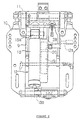
- FIG 3 is a view from the opposite direction of arrow A in Figure 1 which shows the internal structure of the hydro-tilt apparatus 12 that is installed as described above between the brackets 9 and 10.
- the hydro-tilt apparatus 12 has an integral structure and is composed of a hydraulic cylinder 13 comprising a cylinder case 14 and piston 15 (stationary piston 16 and free piston 17) and a piston rod 18, further of a gas chamber 19 which compensates for the oil displaced by the piston rod as it extends and retracts with respect to the cylinder, and of a manual valve 20 that opens and closes an oil passage that connects the upper oil chamber with the lower oil chamber inside the cylinder 13.
- the hydro-tilt apparatus 12 of this invention places the gas chamber 19 alongside of the cylinder case 14, and the manual valve 20 is located atop the gas chamber 19 and alongside the top part of the cylinder case 14.
- the cylinder case 14, the gas chamber 19 and the manual valve 20 are all integrated inside one housing into one compact integral unit.
- the apparatus 12 can be more compact in width and still offer adequate capacity of the gas chamber 19, and compared to the conventional example shown in Figure 8, where the gas chamber is placed above the cylinder 14, the device is more compact in length.
- the lower end of the cylinder case 14 that is used as the hydraulic cylinder 13 of the hydro-tilt apparatus 12 is closed by a cap 14a through which the piston rod has been slidably inserted.
- the top of the piston rod 18 connects to the piston 15 (fixed piston 16 and free piston 17) which separates the upper oil chamber from the lower oil chamber inside the cylinder case 14.
- An oil inlet/outlet hole 22 formed in the top area of the side wall of the cylinder case 14 connects the upper oil chamber with the manual valve 20, and, beneath that hole, an oil inlet/outlet hole 23 connects the lower oil chamber with the gas chamber 19.
- a resilient member (disk spring) 24 that can extend and contract in the axial direction of the cylinder case 14 installed on the top surface side of the lid member 14a inside the cylinder case 14 that serves to prevent the cylinder case 14 from breaking due to oil pressure generated by the thermal expansion of the oil when the hydraulic cylinder 13 is in the fully extended position.
- the oil passage that connects the upper oil chamber to the lower oil chamber inside the cylinder 14 of the hydro-tilt apparatus 12
- the oil passage is formed on the side of the cylinder 14 and connects from the oil inlet/outlet on the side of the upper oil chamber to the manual valve 20, and then, through a pipe-like passage 25 in the gas chamber 19, from the bottom of the gas chamber 19 to the oil inlet/outlet in the side of the lower oil chamber.
- the pipe-like passage 25 is formed inside the gas chamber 19 as a part of the oil passage that connects the upper oil chamber to the lower oil chamber in the cylinder, there is no need to form an oil passage in the housing of the apparatus 12.
- the simple operation of inserting a pipe passage inside the gas chamber 19 allows easy formation of the oil passage and contributes to the simplicity and compactness of the apparatus.
- a pipe-like passage 25 runs from the oil inlet/outlet hole 22 at the side of the top oil chamber through the manual valve 20 and to the inside of the gas chamber 19.
- An oil passage formed along the outside of the cylinder case 14 runs from the inside of the gas chamber 19 at its bottom to the oil inlet/outlet hole 23 on the side of the lower oil chamber.
- this manual valve 20 used to open and close the oil passage of the present embodiment of the hydro-tilt apparatus 12, as shown in Figures 1 and 2, this manual valve 20 is rotatably supported by a lid-shaped base plate affixed to the housing of the apparatus 12; the operating shaft 28 can be operated manually by lever 12a.
- a first cam member 29 is integrally affixed to the operating shaft 28, and a second cam member 30 is rotatably supported coaxially on the operating shaft 28, at some distance from the first cam member 29.
- both ball valves close their respective oil-passage sides so that no oil can flow through either side; both ball valves 31, 32 open to allow oil flow in both directions; and one or the other of the ball valves 31, 32 open one side of the oil passage to allow oil to flow in one direction or the other.
- the second ball valve 32 closes the oil passage, the second ball valve 32 functions as a one-way valve, thereby making it possible to switch among three positions.
- three-way switching allows the first ball valve 31 to open the oil passage and the second ball valve 32 to close the oil passage to cause the second ball valve 32 to function as a one-way valve.
- Figure 4 shows the manual valve 20 in the closed condition.
- Figure 5 shows the manual valve 20 open in the one-way direction, and
- Figure 6 shows the manual valve 20 in the open condition.
- the first ball valve 31 retained in the first cam member 29 moves to open the oil passage, but the second ball valve 32 retained in the second cam member 30 does not move and it continues to hold the oil passage closed. Accordingly, the second ball valve 32 functions as a one-way valve that in turn makes it possible for the manual valve 20 to function as a one way valve to allow the oil to flow in one direction.
- the outboard engine can be freely tilted up or down. Also, when the manual valve 20 is in the closed state, the hydraulic cylinder 13 remains fixed. This feature securely fixes the position of the outboard engine. By putting the manual valve 20 in the one-way valve state, it is possible to tilt the outboard engine 1 upward, and even if the operator stops tilting it midway, the outboard engine 1 is held in place and will not tilt down from its own weight.
- the oil passage that connects the upper oil chamber to the lower oil chamber inside the cylinder case 14 is formed as a pipe-like passage inside the gas chamber 19.
- This structure eliminates the need to form a special oil passage in the housing of the apparatus 12 and facilitates the formation of the oil passage inside the pipe by merely requiring the insertion of the pipe, thereby simplifying the apparatus and allowing it to be more compact.
- the present embodiment places a resilient member 24 inside the cylinder case 14 and because the gas chamber 19 and the oil chamber inside the cylinder case 14 are connected by a relief valve consisting of an oil escape passage formed in the housing, there is no need to install a separate relief valve to compensate for me temperature of the hydraulic cylinder, and this feature too makes the apparatus simpler and more compact.
- the manual valve 20 is not limited to the embodiment having this specialized structure, it is possible also to use a conventional opening and closing valve as the manual valve or make other appropriate design changes.
- the hydro-tilt apparatus for outboard engines of this invention allows a sufficient volume for the gas chamber and avoids increasing the overall length or width of the apparatus, thereby making the hydro-tilt apparatus well suited for use on small outboard engines.
- the three-way switchable manual valve is composed of two one-way valves (ball valves 31, 32 and spring 33) which can be switched to a one-way valve configuration by the rotation of the operating shaft and the operation of respective cams 29, 30, the manual valve is easy to operate, compact, and lowcost.
Landscapes
- Engineering & Computer Science (AREA)
- Mechanical Engineering (AREA)
- Physics & Mathematics (AREA)
- Fluid Mechanics (AREA)
- General Engineering & Computer Science (AREA)
- Chemical & Material Sciences (AREA)
- Combustion & Propulsion (AREA)
- Ocean & Marine Engineering (AREA)
- Actuator (AREA)
- Lubrication Of Internal Combustion Engines (AREA)
- Fluid-Damping Devices (AREA)
Claims (10)
- Hydraulische Neigungsvorrichtung für einen Außenbordmotor, die aufweist:dadurch gekennzeichnet, dass das Steuerventil (20) über der Gaskammer (19) angeordnet ist und der Ölkanal längs der Gaskammer (19) gebildet ist, wobei beide innerhalb eines Gehäuses zu einer kompakten, einstückigen Einheit integriert sind.ein Zylindergehäuse (14), das einen Zylinder (13) hat,einen Kolben (15), untergebracht in dem Zylinder (13), der eine erste Ölkammer und eine zweite Ölkammer in dem Zylinder (13) trennt,ein Steuerventil (20), angeordnet in einem Ölkanal, der die erste und die zweite Ölkammer verbindet, wobei eine Gaskammer (19) vorgesehen ist, um das durch eine Kolbenstange (18) des Kolbens (15) verlagerte Öl zu kompensieren, wobei das Steuerventil (20) und die Gaskammer (19) in Reihe miteinander und parallel zu und entlang des Zylinders (13) positioniert sind,
- Hydraulische Neigungsvorrichtung nach Anspruch 1, dadurch gekennzeichnet, dass die Gaskammer (19) in dem Zylindergehäuse (14) einstückig gebildet ist.
- Hydraulische Neigungsvorrichtung nach Anspruch 1 oder 2, dadurch gekennzeichnet, dass das Steuerventil (20) ein manuell betätigtes Ventil ist.
- Hydraulische Neigungsvorrichtung nach einem der Ansprüche 1 bis 3, dadurch gekennzeichnet, dass der Ölkanal zu den oberen und unteren Kammern innerhalb des Zylinders (13) als ein rohrartiger Kanal (25) innerhalb der Gaskammer (19) gebildet ist.
- Hydraulische Neigungsvorrichtung nach einem der Ansprüche 1 bis 4, dadurch gekennzeichnet, dass der Aufbau des Hydraulik - Zylindergehäuses (14), wenn er auf seine maximale Länge erstreckt ist, derart ist, dass das Ende des Zylindergehäuses (14) und des Kolbens (15) im indirekten Kontakt durch ein elastisches Teil (24) sind, das sich in der axialen Richtung des Zylindergehäuses (14) ausdehnen oder zusammenziehen kann.
- Hydraulische Neigungsvorrichtung nach einem der Ansprüche 1 bis 5, dadurch gekennzeichnet, dass das Steuerventil (20) zwei Einwegventile (31, 32) aufweist, die in entgegengesetzte Richtungen gewandt sind, die so positioniert sind, um in der Lage zu sein den Ölkanal zu schließen, wobei jedes ein Schließteil hat, wobei eine gemeinsame Feder (33) zwischen den Schließteilen zusammengedrückt wird und die Schließteile Drücke in entgegengesetzte Richtungen ausüben, und
eine Einrichtung zum Betätigen der zwei Einwegventile (31, 32), die in der Lage ist, sie in Stufen zu betätigen, um gerade ein Schließteil oder beide Schließteile zu verlagern, um dadurch dem Steuerventil (20) zu gestatten, in drei Stufen geschaltet zu werden: beide Ventile geschlossen, ein Ventil offen und eines geschlossen, oder beide Ventile offen. - Hydraulische Neigungsvorrichtung nach Anspruch 6, dadurch gekennzeichnet, dass die Einrichtung zum Betätigen der Ventile einen ersten Nocken (29), befestigt an einer drehbaren Welle (28), einen zweiten Nocken (30), koaxial angeordnet, der sich durch einen vorbeschriebenen Bereich in Bezug auf den ersten Nocken (29) drehen kann, eine Feder (35), die eine Kraft auf den zweiten Nocken (30) ausübt, um ihn in einer Einzelrichtung in Bezug auf den ersten Nocken (29) zu drehen, aufweist, wobei die Nocken (29, 30) und die Feder (35) in solch einer Weise in Bezug auf die Schließteile der Ventile (31, 32) angeordnet sind, dass der erste Nocken (29) ein Schließteil über einen Teil seinen Drehbereiches hält, und dass die Drehbewegung des zweiten Nockens (30), der das andere Schließteil hält, mit derjenigen des ersten Nockens (29) verbunden ist.
- Hydraulische Neigungsvorrichtung nach Anspruch 7, dadurch gekennzeichnet, dass die Einrichtung zum Betätigen der Ventile ein gemeinsames Stoppteil (34) zum Begrenzen des Drehbereiches beider Nocken (29, 30) aufweist.
- Hydraulische Neigungsvorrichtung nach einem der Ansprüche 6 bis 8, dadurch gekennzeichnet, dass die Einwegventile (31, 32) Kugelventile sind, die jeweils eine Kugel als ihr Schließteil haben.
- Hydraulische Neigungsvorrichtung nach einem der Ansprüche 6 bis 9, dadurch gekennzeichnet, dass der erste Nocken (29) einen Eingriffsvorsprung (29a) hat, der in eine Öffnung (30a) in dem zweiten Nocken (30) in einer derartigen Weise eindringt, dass der Vorsprung (29a) in der Drehrichtung über einen vorbeschriebenen Drehwinkel gleiten kann.
Applications Claiming Priority (4)
| Application Number | Priority Date | Filing Date | Title |
|---|---|---|---|
| JP02138298A JP3846823B2 (ja) | 1998-01-19 | 1998-01-19 | ハイドロチルト装置のマニュアルバルブ構造 |
| JP10021381A JPH11201113A (ja) | 1998-01-19 | 1998-01-19 | 船外機のハイドロチルト装置 |
| JP2138298 | 1998-01-19 | ||
| JP2138198 | 1998-01-19 |
Publications (3)
| Publication Number | Publication Date |
|---|---|
| EP0930227A2 EP0930227A2 (de) | 1999-07-21 |
| EP0930227A3 EP0930227A3 (de) | 2001-09-12 |
| EP0930227B1 true EP0930227B1 (de) | 2005-03-30 |
Family
ID=26358429
Family Applications (1)
| Application Number | Title | Priority Date | Filing Date |
|---|---|---|---|
| EP99100892A Expired - Lifetime EP0930227B1 (de) | 1998-01-19 | 1999-01-19 | Hydraulische Neigevorrichtung für einen Aussenbordmotor |
Country Status (3)
| Country | Link |
|---|---|
| US (1) | US6213822B1 (de) |
| EP (1) | EP0930227B1 (de) |
| DE (1) | DE69924418T2 (de) |
Families Citing this family (7)
| Publication number | Priority date | Publication date | Assignee | Title |
|---|---|---|---|---|
| US6662559B1 (en) * | 2000-08-18 | 2003-12-16 | Cook Manufacturing Corporation | Hydraulic actuator |
| JP2002079995A (ja) * | 2000-09-08 | 2002-03-19 | Showa Corp | 船舶推進機用チルト装置の油圧回路 |
| JP2004149000A (ja) * | 2002-10-30 | 2004-05-27 | Showa Corp | 船舶用ガスシリンダ装置 |
| US7901258B1 (en) * | 2007-11-30 | 2011-03-08 | Brp Us Inc. | Hydraulic system for a marine outboard engine |
| US8858279B1 (en) | 2011-05-31 | 2014-10-14 | Brp Us Inc. | Tilt/trim and steering bracket assembly for a marine outboard engine |
| US8851944B1 (en) | 2012-12-20 | 2014-10-07 | Brp Us Inc. | Marine engine hydraulic system |
| CN107667053B (zh) * | 2015-04-29 | 2021-01-22 | 克拉克设备公司 | 履带张紧装置 |
Family Cites Families (19)
| Publication number | Priority date | Publication date | Assignee | Title |
|---|---|---|---|---|
| US3983835A (en) * | 1975-04-24 | 1976-10-05 | Outboard Marine Corporation | Gas pressurized hydraulic marine propulsion tilting system with automatic let-down assembly |
| US4121736A (en) | 1976-08-23 | 1978-10-24 | Mcgaw Jr Wilbert Hersman | Hand held atomizer washing device |
| JPS5795295A (en) * | 1980-12-03 | 1982-06-14 | Yamaha Motor Co Ltd | Tilting lock device of outboard engine |
| JPS57130893A (en) * | 1981-01-31 | 1982-08-13 | Sanshin Ind Co Ltd | Tilt lever returning device for outer-ship machine |
| JPS58185397A (ja) | 1982-04-26 | 1983-10-29 | Sanshin Ind Co Ltd | 船舶推進機のチルトロツク装置 |
| JPS58214495A (ja) | 1982-06-08 | 1983-12-13 | Sanshin Ind Co Ltd | 船舶推進機のチルトロツク装置 |
| JPS59120596A (ja) | 1982-12-28 | 1984-07-12 | Sanshin Ind Co Ltd | 船舶推進機のチルトロツク装置 |
| JPS59153694A (ja) | 1983-02-22 | 1984-09-01 | Sanshin Ind Co Ltd | 船舶推進機のチルト装置 |
| JPS59153693A (ja) | 1983-02-22 | 1984-09-01 | Sanshin Ind Co Ltd | 船舶推進機のチルトロツク装置 |
| JPS60116592A (ja) | 1983-11-29 | 1985-06-24 | Sanshin Ind Co Ltd | 船舶推進機のチルトロック装置 |
| US4605377A (en) | 1984-06-21 | 1986-08-12 | Outboard Marine Corporation | Manual lift means for marine propulsion device |
| US4925411A (en) | 1987-06-01 | 1990-05-15 | Outboard Marine Corporation | Marine propulsion device tilt and trim mechanism |
| US4944705A (en) | 1987-10-26 | 1990-07-31 | Kayaba Kogyo Kabushiki Kaisha | Tilt damper |
| US5358436A (en) * | 1990-04-24 | 1994-10-25 | Honda Giken Kogyo Kabushiki Kaisha | Tilt cylinder device for outboard engine |
| JP3054487B2 (ja) | 1992-02-26 | 2000-06-19 | 三信工業株式会社 | 船外機のチルトロック装置 |
| JP3126069B2 (ja) * | 1992-04-27 | 2001-01-22 | 株式会社ショーワ | 船外機のチルトシリンダユニット |
| US5389019A (en) * | 1992-07-16 | 1995-02-14 | Sanshin Kogyo Kabushiki Kaisha | Tilt mechanism for outboard drive unit |
| US5489226A (en) * | 1993-09-13 | 1996-02-06 | Sanshin Kogyo Kabushiki Kaisha | Hydraulic assist device for marine propulsion unit |
| JP3404709B2 (ja) | 1993-12-30 | 2003-05-12 | ヤマハマリン株式会社 | 船外機における推進ユニットの姿勢保持装置 |
-
1999
- 1999-01-19 DE DE69924418T patent/DE69924418T2/de not_active Expired - Lifetime
- 1999-01-19 EP EP99100892A patent/EP0930227B1/de not_active Expired - Lifetime
- 1999-01-19 US US09/234,091 patent/US6213822B1/en not_active Expired - Lifetime
Also Published As
| Publication number | Publication date |
|---|---|
| US6213822B1 (en) | 2001-04-10 |
| EP0930227A3 (de) | 2001-09-12 |
| EP0930227A2 (de) | 1999-07-21 |
| DE69924418T2 (de) | 2005-08-11 |
| DE69924418D1 (de) | 2005-05-04 |
Similar Documents
| Publication | Publication Date | Title |
|---|---|---|
| CA2502317C (en) | Tiller operated power assist marine steering system | |
| US4976636A (en) | Trim apparatus for marine propulsion unit | |
| EP0930227B1 (de) | Hydraulische Neigevorrichtung für einen Aussenbordmotor | |
| US4582082A (en) | Piston-driven valves | |
| US6620006B2 (en) | Tilt and trim control and cowling arrangement for marine drive | |
| JPH0717233B2 (ja) | 船舶推進機のチルト装置 | |
| US6309265B1 (en) | Power tilt and trim system for outboard drive | |
| US6139380A (en) | Compact power tilt and trim unit for marine drive | |
| JP3912006B2 (ja) | 船外機のステアリング構造 | |
| JPH06104474B2 (ja) | 舶用推進装置 | |
| US5954554A (en) | Outboard drive exhaust system | |
| JP3747235B2 (ja) | 船外機のパワー・トリム・チルト装置 | |
| JP3947258B2 (ja) | 船舶用推進装置の上下揺動装置 | |
| US5444979A (en) | Fluid passage control device for fluid pressure actuator | |
| EP2053232A1 (de) | Durchflussschaltventil | |
| JP3846823B2 (ja) | ハイドロチルト装置のマニュアルバルブ構造 | |
| JP3534358B2 (ja) | 船外推進機のパワー・トリム・チルト装置 | |
| US6857921B2 (en) | Marine gas cylinder apparatus | |
| US6276976B1 (en) | Tilt and trim system for outboard drive | |
| US6309264B1 (en) | Cylinder assembly for marine propulsion unit | |
| JPH10129593A (ja) | 船舶用推進機のチルトシリンダ装置 | |
| US6159061A (en) | Tilting apparatus for marine propulsion unit | |
| US5368509A (en) | Tilt lock system for outboard motor | |
| US5389019A (en) | Tilt mechanism for outboard drive unit | |
| JPH10250689A (ja) | 船舶用推進装置の上下揺動装置 |
Legal Events
| Date | Code | Title | Description |
|---|---|---|---|
| PUAI | Public reference made under article 153(3) epc to a published international application that has entered the european phase |
Free format text: ORIGINAL CODE: 0009012 |
|
| AK | Designated contracting states |
Kind code of ref document: A2 Designated state(s): AT BE CH CY DE DK ES FI FR GB GR IE IT LI LU MC NL PT SE Kind code of ref document: A2 Designated state(s): DE FR SE |
|
| AX | Request for extension of the european patent |
Free format text: AL;LT;LV;MK;RO;SI |
|
| PUAL | Search report despatched |
Free format text: ORIGINAL CODE: 0009013 |
|
| AK | Designated contracting states |
Kind code of ref document: A3 Designated state(s): AT BE CH CY DE DK ES FI FR GB GR IE IT LI LU MC NL PT SE |
|
| AX | Request for extension of the european patent |
Free format text: AL;LT;LV;MK;RO;SI |
|
| 17P | Request for examination filed |
Effective date: 20010910 |
|
| AKX | Designation fees paid |
Free format text: DE FR SE |
|
| 17Q | First examination report despatched |
Effective date: 20020715 |
|
| RAP1 | Party data changed (applicant data changed or rights of an application transferred) |
Owner name: SANSHIN KOGYO K.K. Owner name: SOQI K.K. |
|
| RAP1 | Party data changed (applicant data changed or rights of an application transferred) |
Owner name: YAMAHA MARINE KABUSHIKI KAISHA Owner name: SOQI K.K. |
|
| GRAP | Despatch of communication of intention to grant a patent |
Free format text: ORIGINAL CODE: EPIDOSNIGR1 |
|
| GRAS | Grant fee paid |
Free format text: ORIGINAL CODE: EPIDOSNIGR3 |
|
| GRAA | (expected) grant |
Free format text: ORIGINAL CODE: 0009210 |
|
| AK | Designated contracting states |
Kind code of ref document: B1 Designated state(s): DE FR SE |
|
| REF | Corresponds to: |
Ref document number: 69924418 Country of ref document: DE Date of ref document: 20050504 Kind code of ref document: P |
|
| REG | Reference to a national code |
Ref country code: SE Ref legal event code: TRGR |
|
| PLBE | No opposition filed within time limit |
Free format text: ORIGINAL CODE: 0009261 |
|
| STAA | Information on the status of an ep patent application or granted ep patent |
Free format text: STATUS: NO OPPOSITION FILED WITHIN TIME LIMIT |
|
| ET | Fr: translation filed | ||
| 26N | No opposition filed |
Effective date: 20060102 |
|
| REG | Reference to a national code |
Ref country code: FR Ref legal event code: TQ |
|
| REG | Reference to a national code |
Ref country code: FR Ref legal event code: PLFP Year of fee payment: 17 |
|
| PGFP | Annual fee paid to national office [announced via postgrant information from national office to epo] |
Ref country code: DE Payment date: 20150121 Year of fee payment: 17 |
|
| PGFP | Annual fee paid to national office [announced via postgrant information from national office to epo] |
Ref country code: SE Payment date: 20150121 Year of fee payment: 17 Ref country code: FR Payment date: 20150122 Year of fee payment: 17 |
|
| REG | Reference to a national code |
Ref country code: DE Ref legal event code: R119 Ref document number: 69924418 Country of ref document: DE |
|
| REG | Reference to a national code |
Ref country code: FR Ref legal event code: ST Effective date: 20160930 |
|
| PG25 | Lapsed in a contracting state [announced via postgrant information from national office to epo] |
Ref country code: DE Free format text: LAPSE BECAUSE OF NON-PAYMENT OF DUE FEES Effective date: 20160802 |
|
| PG25 | Lapsed in a contracting state [announced via postgrant information from national office to epo] |
Ref country code: FR Free format text: LAPSE BECAUSE OF NON-PAYMENT OF DUE FEES Effective date: 20160201 Ref country code: SE Free format text: LAPSE BECAUSE OF NON-PAYMENT OF DUE FEES Effective date: 20160120 |