EP0930419A1 - Aube de turbine a gas - Google Patents
Aube de turbine a gas Download PDFInfo
- Publication number
- EP0930419A1 EP0930419A1 EP98923104A EP98923104A EP0930419A1 EP 0930419 A1 EP0930419 A1 EP 0930419A1 EP 98923104 A EP98923104 A EP 98923104A EP 98923104 A EP98923104 A EP 98923104A EP 0930419 A1 EP0930419 A1 EP 0930419A1
- Authority
- EP
- European Patent Office
- Prior art keywords
- blade
- coolant
- flow passage
- steam
- coolant flow
- Prior art date
- Legal status (The legal status is an assumption and is not a legal conclusion. Google has not performed a legal analysis and makes no representation as to the accuracy of the status listed.)
- Withdrawn
Links
Images


Classifications
-
- F—MECHANICAL ENGINEERING; LIGHTING; HEATING; WEAPONS; BLASTING
- F01—MACHINES OR ENGINES IN GENERAL; ENGINE PLANTS IN GENERAL; STEAM ENGINES
- F01D—NON-POSITIVE DISPLACEMENT MACHINES OR ENGINES, e.g. STEAM TURBINES
- F01D5/00—Blades; Blade-carrying members; Heating, heat-insulating, cooling or antivibration means on the blades or the members
- F01D5/12—Blades
- F01D5/14—Form or construction
- F01D5/147—Construction, i.e. structural features, e.g. of weight-saving hollow blades
-
- F—MECHANICAL ENGINEERING; LIGHTING; HEATING; WEAPONS; BLASTING
- F01—MACHINES OR ENGINES IN GENERAL; ENGINE PLANTS IN GENERAL; STEAM ENGINES
- F01D—NON-POSITIVE DISPLACEMENT MACHINES OR ENGINES, e.g. STEAM TURBINES
- F01D5/00—Blades; Blade-carrying members; Heating, heat-insulating, cooling or antivibration means on the blades or the members
- F01D5/12—Blades
- F01D5/14—Form or construction
- F01D5/18—Hollow blades, i.e. blades with cooling or heating channels or cavities; Heating, heat-insulating or cooling means on blades
- F01D5/187—Convection cooling
-
- F—MECHANICAL ENGINEERING; LIGHTING; HEATING; WEAPONS; BLASTING
- F05—INDEXING SCHEMES RELATING TO ENGINES OR PUMPS IN VARIOUS SUBCLASSES OF CLASSES F01-F04
- F05D—INDEXING SCHEME FOR ASPECTS RELATING TO NON-POSITIVE-DISPLACEMENT MACHINES OR ENGINES, GAS-TURBINES OR JET-PROPULSION PLANTS
- F05D2260/00—Function
- F05D2260/20—Heat transfer, e.g. cooling
- F05D2260/232—Heat transfer, e.g. cooling characterized by the cooling medium
- F05D2260/2322—Heat transfer, e.g. cooling characterized by the cooling medium steam
Definitions
- the present invention relates to a gas-turbine blade provided with a steam-cooled structure.
- FIG. 5a A typical internal cooling structure of a moving blade in a conventional heat recovery type steam-cooled gas turbine, such as mentioned above, is shown in Figs. 5a and 5b.
- Fig. 5a is a vertical section of a blade
- Fig. 5b is a sectional view of same along the line 5B-5B in Fig. 5a.
- Steam for cooling the moving blade 1 is supplied through a cooling steam inlet port 8 provided in a lower end portion of the blade at a location close to a leading edge 5 of the blade, and the steam flows through a coolant flow passage 4 formed inside the moving blade 1 in a serpentine pattern, as indicated by the arrows. After having cooled the interior of the blade, the steam leaves the blade through a cooling steam outlet port 9 provided at a location close to the blade trailing edge 6 and is subsequently introduced into a recovery system not shown.
- a plurality of turbulence promoting fins 7 are formed on the inner surfaces of the coolant flow passage 4 in the blade, each extending in a direction substantially orthogonal to the flow of the coolant steam so as to promote internal heat transfer.
- the coolant steam is recovered by equipment provided at a location downstream of the gas turbine.
- the pressure of the coolant steam within the blade is maintained higher than the pressure of gases flowing outside of the blade by ca. 2 to 4 MPa.
- the blade is subjected to internal pressures which may exceed a permissible limit predetermined by the strength of the hollow blade with a thin structure, thus involving deformation (bulging) of the blade and hence fluid delamination of the working gas flowing along the external surface of the blade, to incur such problems as degradation in the performance of the blade and the like.
- an object of the present invention is to provide a gas-turbine blade in which strength can be reliably ensured without impairing the advantages of the steam cooling system designed to improve the thermal efficiency of the gas turbine to thus be able to freely enjoy such advantages.
- the present invention has been made to achieve the object described above and provides a gas-turbine blade having a coolant flow passage formed to extend longitudinally in an inner portion of the blade, wherein a reinforcing rib or ribs are provided within the coolant flow passage so as to extend in a flow direction of a coolant and connect a dorsal wall and a ventral wall of the blade.
- the blade By connecting the dorsal wall and the ventral wall of the blade by means of reinforcing rib or ribs, the blade can be imparted with sufficient strength for withstanding a force applied by a pressure difference between the high-pressure steam flowing inside of the blade and the gas flowing outside of the blade. Further, since the reinforcing rib or ribs are disposed so as to extend in the direction in which the coolant flows through the coolant flow passage, the high-pressure steam serving as the coolant encounters essentially no obstacle in flowing through the coolant flow passage. Thus, the flow of the coolant is not essentially effected by the presence (or absence) of the reinforcing rib or ribs, whereby the desired cooling effect as aimed can be achieved.
- the present invention provides a gas-turbine blade, in which the coolant flow passage is formed, being partitioned by a partition wall or walls, and in which the reinforcing rib is disposed at such a position that coolant flow passage portions located at right and left sides of the reinforcing rib or ribs, together with the partition walls located adjacent to the reinforcing rib are not blocked.
- the width of the coolant flow passage is correspondingly decreased, which is effective for preventing the deformation of the blade (bulging) by the pressure difference between the coolant steam pressure within the coolant flow passage and the main gas flow.
- the blade can be protected against deformation even when a coolant steam of higher pressure than that of the main gas flow is used, whereby degradation of the blade performance which may otherwise be brought about by so-called fluid delamination due to blade deformation can be suppressed or prevented.
- the present invention provides a gas-turbine blade, in which the coolant flow passage portions located at left and right sides of the reinforcing rib or ribs are each formed as independent structures, such that the coolant flow passage portions exhibit independent flow characteristics.
- the reinforcing rib or ribs are not simply disposed within the coolant flow passage but disposed such that the coolant flow passage portions defined at the left and right sides thereof can be constructed independently according to the characteristics of the coolant steam flowing through the respective coolant flow passage portions. Hence, efficient heat exchange and heat recovery can be achieved.
- the present invention provides a gas-turbine blade, in which the blade is structured so that the coolant steam fed to the coolant flow passage and recovered therefrom is fed through an inlet port projecting forwardly from a root portion of the blade and recovered through an outlet port projecting rearwardly from the blade root portion.
- these ports are formed so as to project forwardly and rearwardly, respectively, from the blade root as described above. Hence, the machining of these portions, including connecting structures, etc., is facilitated, while the leakage of the steam at the connecting portions which degrades of the operating efficiency can be appropriately and reliably prevented.
- the present invention provides a gas-turbine blade, in which the reinforcing rib or ribs are disposed only within a portion of the coolant flow passage which is located adjacent to the blade trailing edge, while the other portion of said coolant flow passage is partitioned a number of times at short intervals such that the cross-sections thereof are approximately circular.
- the coolant flow passage is partitioned a number of times at short intervals such that the cross-sections thereof are approximately circular, there is no need to provide the reinforcing rib or ribs within the coolant flow passage portions each having approximately circular cross-sections. Accordingly, reinforcing ribs are not disposed in the coolant flow passage portions having the approximately circular cross-sections but may be selectively disposed in only the coolant flow passage portion extending adjacent to the blade trailing edge which has a narrow cross-section and which is difficult to form with a roughly circular cross-section. Hence, the cost involved in designing and manufacturing the blade in which the reinforcing ribs are disposed over the entire blade can be eliminated while sufficient strength can be ensured for the blade as a whole.
- the present invention provides a steam-cooled blade to which the coolant steam is fed from a hub side at the blade trailing edge, wherein the coolant flow passage portion located closest to the blade trailing edge is made wide to facilitate the flow of the coolant steam, while an end portion of the reinforcing rib disposed adjacent to the blade trailing edge is bent curvilinearly toward a corner portion of the blade.
- the flow of the coolant steam at the corner portion of the blade can be facilitated and the blade cooling performance can be enhanced.
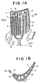
- FIG. 1a shows a vertical section of a steam-cooled moving blade for a gas turbine
- Fig. 1b shows a cross-sectional view of same taken along line 1B-1B in Fig. 1a.
- same parts or portions as those of the conventional blade structure described hereinbefore are denoted by like reference numerals in the figures, hence their description is omitted here.
- reinforcing ribs 12 are disposed so as to extend longitudinally in a substantially center portion of a coolant flow passage 4 which reciprocatively extends longitudinally from a blade root to a blade tip 11, and then from the blade tip 11 to the blade root so as to be an interconnected serpentine pattern in an inner portion of a moving blade 1, and connect a ventral wall 2 and a dorsal wall 3.
- reinforcing ribs 13 with short lengths and which are bent to conform to the curves of turn-around portions are disposed, respectively, at each turn-around portion of the serpentine coolant flow passage 4 in the regions located near the blade tip end portion 11.
- the blade structure according to this embodiment of the present invention which incorporates the reinforcing ribs 12 and 13 disposed within the coolant flow passage 4 as described above, a sufficiently high strength can be ensured for the blade so that the moving blade 1 can withstand a force applied thereto under the pressure difference (ordinarily in a range of 2 to 4 MPa) between the coolant steam of high pressure flowing through the coolant flow passage 4 and a main gas flow 10 flowing outside of the moving blade 1.
- the reinforcing ribs 12 are disposed in the longitudinal direction of the blade in which the coolant flow passage 4 extends, the reinforcing ribs 12 are oriented parallel to the flow of the coolant steam. This is preferable for suppressing the occurrence of turbulence in the coolant steam flow.
- the reinforcing ribs 13 are bent curvilinearly along the turn-around path of the coolant flow passage 4, the coolant steam flow can be introduced smoothly to the blade tip 11.
- no special difference can be found with regard to the flow of the coolant steam.
- the desired cooling effect can be achieved without degrading the advantageous effects which can be obtained by using steam as the coolant.
- the reinforcing ribs 12 and 13 are shaped so as to incur less pressure loss hydrodynamically, i.e., by rounding the leading edges and trailing edges of the reinforcing ribs 12 and 13, while concerning the size of the reinforcing ribs, the width thereof should be determined so as to be capable of exhibiting sufficiently high strength to withstand the tension applied from the ventral wall 2 and the dorsal wall 3 of the moving blade 1.
- the concrete dimensions of the reinforcing ribs 12 and 13 may be determined in consideration of the scale of the turbine used.
- Figure 2a shows a vertical section of a steam-cooled moving blade of a gas turbine
- Fig. 2b shows a cross-sectional view of same taken along line 2B-2B in Fig. 2a.
- a coolant flow passage 4 being bent in a serpentine pattern, is formed by a U-shape partition wall 14a and an I-shape partition wall 14b which is inserted at a center portion of the U-shape partition wall 14a, wherein reinforcing ribs 12 are disposed at substantially central positions between the U-shape partition wall 14a and the I-shape partition wall 14b for ensuring the strength of the blade at portions which correspond to the coolant flow passage 4.
- turbulence promoting fins (turbulators) 7a and 7b formed at the right and left sides, respectively, of the reinforcing rib 12 disposed within the coolant flow passage 4 present some aspects which differ from the corresponding structure of the reinforcing rib 12 disposed in the other portion of the coolant flow passage 4.
- the reinforcing ribs 12 are simply disposed on the turbulence promoting fins 7 which extend uniformly over the entire width of the coolant flow passage 4.
- the turbulence promoting fins 7 are independently arrayed at the left and right sides of the reinforcing rib 12.
- the turbulence promoting fins 7a and the turbulence promoting fins 7b disposed at the left and right sides of the reinforcing rib 12 located near the blade trailing edge differ from each other with regard to the direction of inclination and the number of fins (mesh of the array).
- each turbulence promoting fin mentioned above is adopted in consideration of the fact that the behavior of the coolant steam flowing at one side of the reinforcing rib 12 differs somewhat from that of the coolant steam flowing at the other side. Accordingly, in the case of this embodiment of the invention, the turbulence promoting fins are arrayed so that a flow of the coolant steam appropriate for the desired behavior of the coolant steam at the respective location can be obtained, and thus, efficient heat exchange and heat recovery is obtained.
- a coolant steam inlet port 8 is provided at the blade root portion of the moving blade 1 so as to project slightly forwardly at the leading edge side while a coolant steam outlet port 9 is so provided at the trailing edge side as to project slightly rearwardly.
- Figure 3a shows a vertical section of a steam-cooled moving blade of a gas turbine
- Fig. 3b shows a cross-sectional view of same taken along line 3B-3B in Fig. 3a.
- the reinforcing ribs 12 are disposed in association with only the portion of the serpentine coolant flow passage 4 that is located close to the blade trailing end of the moving blade 1.
- a greater number of partition walls 14 are employed for defining the coolant flow passages 4 bent in the serpentine pattern formed in an inner portion of the moving blade 1.
- the interior of the blade 1 is partitioned more finely (e.g. partitioned into six portions rather than four portions in the ordinary array), whereby each portion of the coolant flow passage 4 is formed to have an approximately circular in cross-section, which contributes to increasing the strength of the blade.
- the partition wall 14 is not provided to form the portion of the coolant flow passage 4 located along the trailing edge in an approximately the circular shape. Instead, the reinforcing ribs 12 are provided in this portion in order to ensure the strength of the blade.
- the partition walls 14 are disposed at short intervals in a region extending from the blade leading edge of the moving blade 1 to the central portion thereof and hence to the one immediately before the trailing edge, and the coolant flow passage 4 is strengthened because it has an approximately circular cross-section.
- the reinforcing ribs are disposed selectively within only the portion of the coolant flow passage 4 that is located along the blade trailing edge where difficulty is encountered in forming the slender cross-section of the coolant flow passage 4 to be approximately circular. Consequently, the expense involved in designing and manufacturing the blade having reinforcing ribs disposed all over can be eliminated while yet obtaining a blade having sufficient strength.
- bypass aperture 16 are provided in lower portions of the partition walls 14 for allowing parts of the coolant steam flowing through the coolant flow passage 4 to bypass the serpentine portions thereof, so that the temperature balance, etc. over the entire blade is regulated.
- Figures 4a and 4b show a sectional view of a steam-cooled moving blade for a gas turbine according to a fourth embodiment of the present invention, wherein Fig. 4a shows the moving blade in a cross-section taken in the radial direction of the gas turbine, i.e., in the longitudinal direction of the moving blade, and Fig. 4b shows a section of same taken along line 4B-4B in Fig. 4b.
- the widths of the passage portions are such that the portion defined by the associated rib located nearest to the blade trailing edge 6 is the largest, as indicated by the pitch 17, while the widths of the other adjacent passage portions are narrow so that the passage portion located closest to the blade trailing edge 6 has the greatest width for allowing the coolant steam to flow easily.
- an end 12-1 of the reinforcing rib 12 which is disposed closest to the blade trailing edge 6 and which is located near the blade tip 11 is bent so as to face a corner portion 18 of the moving blade 1 what is formed at a position where the blade tip 11 and the blade trailing edge 6 intersect each other.
- the flow of the coolant steam can reliably and sufficiently reach the corner portion 18.
- the coolant steam supplied from a rotor, not shown, to the moving blade 1 by way of the coolant steam inlet port 8b formed at the blade leading edge side and the coolant steam inlet port 8a provided at the blade trailing edge side can flow through the coolant flow passages 4, communicated with the coolant steam inlet port 8a and the coolant steam inlet port 8b, turns around at the blade tip 11, and flows back to the hub by way of coolant steam outlet ports 9a and 9b.
- the portion of the coolant flow passage 4 located nearest the blade trailing edge 6 is finely partitioned a number of time at short intervals by disposing a reinforcing rib or ribs 12 within the coolant flow passage 4 in such manner as mentioned previously, wherein the passage portion located closest to the blade trailing edge 6 has a greater width or pitch 17 so that the passage portion space adjacent to the blade trailing edge 6 has a large width for allowing the coolant steam to flow easily therethrough (notwithstanding the fact that blade thickness is reduced at the blade trailing edge 6), whereas the intervals between the reinforcing ribs 12 located farther from the blade trailing edge 6 are short, making it difficult for the coolant steam to flow compared to the steam flowing through the passage portion located nearest to the trailing edge.
- the coolant steam supplied to the portion where it is difficult for the coolant steam to flow is forced to flow through the passage portion located closest to the blade trailing edge 6 where it is easy for the coolant steam to flow. In this manner, a sufficient cooling effect can be ensured even for the passage portion of the internal coolant flow passage located close to the blade trailing edge 6.
- the passage portion of the coolant flow passage 4 located closest to the blade trailing edge 6 is partitioned into four flow channels by disposing three reinforcing ribs 12, the present invention is not restricted to any specific number of the reinforcing ribs 12 and the flow channels. It goes without saying that the numbers mentioned above can be altered appropriately depending on the shape of the moving blade 1 and the scale of the gas turbine used in practical application.
- the coolant flow passage 4 is at a minimum a serpentine pattern which extends from the hub, turns around at the blade tip 11 and extends backward to the coolant steam outlet ports 9a and 9b, it goes without saying that a large scale serpentine structure in which the coolant steam is forced to turn around an arbitrary number of times can be adopted depending on the design and manufacturing requirements.
- the blade by providing the reinforcing rib or ribs within the coolant flow passage internally formed in the moving blades, the blade can be obtained which is capable of withstanding the force brought about under the pressure difference between the high-pressure steam flowing through the interior of the blade and the main gas stream flowing outside of the blade, and which has high safety and stability.
- the reinforcing ribs are structured such that individual reinforcing ribs extend substantially in parallel with the flow of the coolant steam, a blade can be obtained in which the coolant steam flows through the internal passage(s) as smoothly as in the blade where no reinforcing ribs are provided.
- the desired effects can be achieved without degrading the internal convection cooling performance.
- the strength of the blade can be ensured without impairing the advantages obtained by using steam instead of air for cooling the blade to improve the thermal efficiency of the gas turbine. Consequently, the efficiency of the gas turbine and the plant as a whole can be increased.
- the reinforcing ribs are disposed at a position such that the passage portion formed between the reinforcing rib and the adjacent partition wall at the left or right side thereof is not blocked. More specifically, by disposing the reinforcing ribs, at a central position relative to the adjacent partition wall, which together with the reinforcing ribs forms the coolant flow passage, so as not to block the coolant flow passage, the width of the coolant flow passage is decreased. This is effective for suppressing deformation of the blade under the pressure difference between the coolant steam pressure within the coolant flow passage and that of the main gas stream.
- the blade can be protected against deformation even when the pressure of the coolant steam is higher than that of the main gas stream, whereby degradation of the blade performance which may otherwise be brought about by so-called fluid delamination caused by blade deformation or bulging can be prevented.
- the passage portions defined at the left and right sides of the reinforcing rib or ribs disposed within the coolant flow passage formed within the gas-turbine blade are each formed with an independent structure and exhibit independent flow characteristics.
- the reinforcing rib or ribs are not simply disposed within the coolant flow passage but disposed such that the coolant flow passage portions located at the left and right sides thereof can be constructed independent from each other with appropriate configurations according to the characteristics of the coolant steam flowing through the respective coolant flow passage portions. Hence, efficient heat exchange and heat recovery can be achieved.
- the coolant steam fed to the coolant flow passage formed within the gas-turbine blade and then recovered therefrom, is fed through the inlet port projecting forwardly from the blade root and recovered through the outlet port projecting rearwardly from the blade root.
- these ports are formed so as to project forwardly and rearwardly, respectively, from the blade root portion as described above. Hence, the machining of these portions, including connecting structures, etc., can be facilitated, while the leakage of the steam at the connecting portions which degrades the operating efficiency can be appropriately and reliably prevented.
- the reinforcing rib or ribs to be disposed within the coolant flow passage formed within the gas-turbine blade are provided only within the portion of the coolant flow passage located adjacent to the blade trailing edge, while the other portion of said coolant flow passage is partitioned a number of times at short intervals such that the cross-sections thereof are approximately circular.
- reinforcing ribs are not disposed in the coolant flow passage portions having the approximately circular cross-sections but may be selectively disposed in only the coolant flow passage portion extending adjacent to the blade trailing edge which has a narrow cross-section and which is difficult to form with a roughly circular cross-section.
- the cost involved in designing and manufacturing the blade in which the reinforcing ribs are disposed over the entire blade can be eliminated while sufficient strength can be ensured for the blade as a whole.
- the portion of the coolant passage formed along the blade trailing edge is partitioned a number of times by ribs extending in the longitudinal direction of the blade.
- the portion of the coolant flow passage located closest to the blade trailing edge is made wide to facilitate the flow of the coolant steam, while the end of the reinforcing rib disposed adjacent to the blade trailing edge is curved toward the corner portion of the blade.
- the portion of the coolant flow passage at the inherently thin blade trailing edge may be partitioned a number of times by ribs extending in the longitudinal direction of the blade.
- the portion of the coolant flow passage located closest to the blade trailing edge is partitioned to have a relatively large width so that the flow of the steam is facilitated in this area, while the end portion of the rib disposed closest to the blade trailing edge is curved toward the corner of the blade located at the trailing edge thereof.
Landscapes
- Engineering & Computer Science (AREA)
- Mechanical Engineering (AREA)
- General Engineering & Computer Science (AREA)
- Architecture (AREA)
- Turbine Rotor Nozzle Sealing (AREA)
Applications Claiming Priority (5)
| Application Number | Priority Date | Filing Date | Title |
|---|---|---|---|
| JP14923497 | 1997-06-06 | ||
| JP14923497A JP3322607B2 (ja) | 1997-06-06 | 1997-06-06 | ガスタービン翼 |
| JP27579897A JP3358975B2 (ja) | 1997-10-08 | 1997-10-08 | ガスタービン翼 |
| JP27579897 | 1997-10-08 | ||
| PCT/JP1998/002454 WO1998055735A1 (fr) | 1997-06-06 | 1998-06-03 | Aube de turbine a gas |
Publications (2)
| Publication Number | Publication Date |
|---|---|
| EP0930419A1 true EP0930419A1 (fr) | 1999-07-21 |
| EP0930419A4 EP0930419A4 (fr) | 2001-03-07 |
Family
ID=26479173
Family Applications (1)
| Application Number | Title | Priority Date | Filing Date |
|---|---|---|---|
| EP98923104A Withdrawn EP0930419A4 (fr) | 1997-06-06 | 1998-06-03 | Aube de turbine a gas |
Country Status (4)
| Country | Link |
|---|---|
| US (1) | US6257830B1 (fr) |
| EP (1) | EP0930419A4 (fr) |
| CA (1) | CA2262701C (fr) |
| WO (1) | WO1998055735A1 (fr) |
Cited By (8)
| Publication number | Priority date | Publication date | Assignee | Title |
|---|---|---|---|---|
| EP1116861A3 (fr) * | 2000-01-13 | 2003-12-03 | General Electric Company | Circuit et méthode de refroidissement pour des aubes de turbines à gaz |
| EP1526251A1 (fr) * | 2003-10-22 | 2005-04-27 | General Electric Company | Configuration de refroidissement pour une aube de turbine |
| EP1577497A1 (fr) * | 2004-03-01 | 2005-09-21 | ALSTOM Technology Ltd | Aube de turbomachine refroidie |
| EP1788195A3 (fr) * | 2005-11-18 | 2010-12-08 | Rolls-Royce plc | Aubes pour moteurs à turbine à gaz |
| EP2538026A3 (fr) * | 2011-06-22 | 2017-12-27 | United Technologies Corporation | Système de refroidissement pour aube de turbine incluant des projectures en forme de cône de glace |
| US20190017386A1 (en) * | 2017-07-14 | 2019-01-17 | United Technologies Corporation | Gas turbine engine hollow fan blade rib orientation |
| CN111648830A (zh) * | 2020-05-14 | 2020-09-11 | 西安交通大学 | 一种用于涡轮动叶后部的内冷带肋通道 |
| EP3054093B1 (fr) * | 2015-02-09 | 2022-02-09 | Raytheon Technologies Corporation | Agencement de nervures décalées |
Families Citing this family (33)
| Publication number | Priority date | Publication date | Assignee | Title |
|---|---|---|---|---|
| US6132169A (en) * | 1998-12-18 | 2000-10-17 | General Electric Company | Turbine airfoil and methods for airfoil cooling |
| EP1022435B1 (fr) * | 1999-01-25 | 2009-06-03 | General Electric Company | Circuit de refroidissement interne pour une aube de turbine à gaz |
| US6939102B2 (en) * | 2003-09-25 | 2005-09-06 | Siemens Westinghouse Power Corporation | Flow guide component with enhanced cooling |
| US20070122280A1 (en) * | 2005-11-30 | 2007-05-31 | General Electric Company | Method and apparatus for reducing axial compressor blade tip flow |
| US7445432B2 (en) * | 2006-03-28 | 2008-11-04 | United Technologies Corporation | Enhanced serpentine cooling with U-shaped divider rib |
| US7547191B2 (en) * | 2006-08-24 | 2009-06-16 | Siemens Energy, Inc. | Turbine airfoil cooling system with perimeter cooling and rim cavity purge channels |
| US7645122B1 (en) | 2006-12-01 | 2010-01-12 | Florida Turbine Technologies, Inc. | Turbine rotor blade with a nested parallel serpentine flow cooling circuit |
| US7934906B2 (en) * | 2007-11-14 | 2011-05-03 | Siemens Energy, Inc. | Turbine blade tip cooling system |
| US8511968B2 (en) * | 2009-08-13 | 2013-08-20 | Siemens Energy, Inc. | Turbine vane for a gas turbine engine having serpentine cooling channels with internal flow blockers |
| EP2333240B1 (fr) * | 2009-12-03 | 2013-02-13 | Alstom Technology Ltd | Aube de turbine en deux parties avec des caractéristiques de refroidissement et de vibrations améliorées |
| CN103119247B (zh) * | 2010-06-23 | 2015-11-25 | 西门子公司 | 燃气涡轮叶片 |
| US8827647B1 (en) * | 2010-06-24 | 2014-09-09 | Florida Turbine Technologies, Inc. | Turbine blade with root section cooling |
| CN103459776B (zh) | 2011-04-22 | 2015-07-08 | 三菱日立电力系统株式会社 | 叶片部件及旋转机械 |
| US8985940B2 (en) * | 2012-03-30 | 2015-03-24 | Solar Turbines Incorporated | Turbine cooling apparatus |
| US9797258B2 (en) * | 2013-10-23 | 2017-10-24 | General Electric Company | Turbine bucket including cooling passage with turn |
| US9551226B2 (en) | 2013-10-23 | 2017-01-24 | General Electric Company | Turbine bucket with endwall contour and airfoil profile |
| US9638041B2 (en) | 2013-10-23 | 2017-05-02 | General Electric Company | Turbine bucket having non-axisymmetric base contour |
| US9670784B2 (en) | 2013-10-23 | 2017-06-06 | General Electric Company | Turbine bucket base having serpentine cooling passage with leading edge cooling |
| US9528379B2 (en) | 2013-10-23 | 2016-12-27 | General Electric Company | Turbine bucket having serpentine core |
| WO2016135779A1 (fr) * | 2015-02-26 | 2016-09-01 | 株式会社 東芝 | Pale de rotor de turbine et turbine |
| WO2016148690A1 (fr) | 2015-03-17 | 2016-09-22 | Siemens Energy, Inc. | Aube de turbine avec structure de guidage tournante à écoulement sans contrainte |
| US10107108B2 (en) | 2015-04-29 | 2018-10-23 | General Electric Company | Rotor blade having a flared tip |
| US10612394B2 (en) * | 2017-07-21 | 2020-04-07 | United Technologies Corporation | Airfoil having serpentine core resupply flow control |
| US10767490B2 (en) * | 2017-09-08 | 2020-09-08 | Raytheon Technologies Corporation | Hot section engine components having segment gap discharge holes |
| US10731478B2 (en) * | 2018-12-12 | 2020-08-04 | Solar Turbines Incorporated | Turbine blade with a coupled serpentine channel |
| US11015455B2 (en) * | 2019-04-10 | 2021-05-25 | Pratt & Whitney Canada Corp. | Internally cooled turbine blade with creep reducing divider wall |
| DE102019125779B4 (de) * | 2019-09-25 | 2024-03-21 | Man Energy Solutions Se | Schaufel einer Strömungsmaschine |
| CN111022127B (zh) * | 2019-11-29 | 2021-12-03 | 大连理工大学 | 一种涡轮叶片尾缘曲线式排气劈缝结构 |
| EP3862537A1 (fr) * | 2020-02-10 | 2021-08-11 | General Electric Company Polska sp. z o.o. | Tuyère de turbine refoidie et segment d'aube de guidage de turbine |
| CN113266436B (zh) * | 2021-05-14 | 2022-10-25 | 西安交通大学 | 用于燃气轮机静叶内部冷却的通道结构及燃气轮机静叶 |
| JP7847031B2 (ja) * | 2022-05-06 | 2026-04-16 | 三菱重工業株式会社 | タービン翼及びガスタービン |
| CN116398252B (zh) * | 2023-02-15 | 2026-01-02 | 中国联合重型燃气轮机技术有限公司 | 涡轮叶片和用于涡轮叶片的扰流结构和燃气轮机 |
| CN116853488B (zh) * | 2023-07-18 | 2025-12-05 | 中国航发沈阳发动机研究所 | 一种升力风扇转子轮盘及其叶片结构 |
Family Cites Families (17)
| Publication number | Priority date | Publication date | Assignee | Title |
|---|---|---|---|---|
| US2700530A (en) | 1948-08-27 | 1955-01-25 | Chrysler Corp | High temperature elastic fluid apparatus |
| US3370829A (en) | 1965-12-20 | 1968-02-27 | Avco Corp | Gas turbine blade construction |
| US4073599A (en) * | 1976-08-26 | 1978-02-14 | Westinghouse Electric Corporation | Hollow turbine blade tip closure |
| US4136516A (en) * | 1977-06-03 | 1979-01-30 | General Electric Company | Gas turbine with secondary cooling means |
| JPS55107005A (en) | 1979-02-13 | 1980-08-16 | United Technologies Corp | Turbine blade |
| GB2165315B (en) * | 1984-10-04 | 1987-12-31 | Rolls Royce | Improvements in or relating to hollow fluid cooled turbine blades |
| JPS62228603A (ja) * | 1986-03-31 | 1987-10-07 | Toshiba Corp | ガスタ−ビンの翼 |
| JPS63120802A (ja) | 1986-11-07 | 1988-05-25 | Toshiba Corp | ガスタ−ビンの羽根 |
| JP2953842B2 (ja) * | 1991-12-16 | 1999-09-27 | 東北電力株式会社 | タービン静翼 |
| JP2684936B2 (ja) * | 1992-09-18 | 1997-12-03 | 株式会社日立製作所 | ガスタービン及びガスタービン翼 |
| WO1994012768A2 (fr) | 1992-11-24 | 1994-06-09 | United Technologies Corporation | Structure d'aube refroidissable |
| US5403159A (en) | 1992-11-30 | 1995-04-04 | United Technoligies Corporation | Coolable airfoil structure |
| US5318404A (en) | 1992-12-30 | 1994-06-07 | General Electric Company | Steam transfer arrangement for turbine bucket cooling |
| JPH08240102A (ja) | 1995-03-02 | 1996-09-17 | Mitsubishi Heavy Ind Ltd | ガスタービンの蒸気冷却翼 |
| US5536143A (en) | 1995-03-31 | 1996-07-16 | General Electric Co. | Closed circuit steam cooled bucket |
| JPH08319852A (ja) | 1995-05-25 | 1996-12-03 | Hitachi Ltd | ガスタービンプラントおよびガスタービンプラントの冷却方法 |
| JPH10280904A (ja) * | 1997-04-01 | 1998-10-20 | Mitsubishi Heavy Ind Ltd | ガスタービン冷却動翼 |
-
1998
- 1998-06-03 US US09/230,983 patent/US6257830B1/en not_active Expired - Lifetime
- 1998-06-03 CA CA002262701A patent/CA2262701C/fr not_active Expired - Fee Related
- 1998-06-03 EP EP98923104A patent/EP0930419A4/fr not_active Withdrawn
- 1998-06-03 WO PCT/JP1998/002454 patent/WO1998055735A1/fr not_active Ceased
Cited By (10)
| Publication number | Priority date | Publication date | Assignee | Title |
|---|---|---|---|---|
| EP1116861A3 (fr) * | 2000-01-13 | 2003-12-03 | General Electric Company | Circuit et méthode de refroidissement pour des aubes de turbines à gaz |
| EP1526251A1 (fr) * | 2003-10-22 | 2005-04-27 | General Electric Company | Configuration de refroidissement pour une aube de turbine |
| US6929445B2 (en) | 2003-10-22 | 2005-08-16 | General Electric Company | Split flow turbine nozzle |
| EP1577497A1 (fr) * | 2004-03-01 | 2005-09-21 | ALSTOM Technology Ltd | Aube de turbomachine refroidie |
| EP1788195A3 (fr) * | 2005-11-18 | 2010-12-08 | Rolls-Royce plc | Aubes pour moteurs à turbine à gaz |
| EP2538026A3 (fr) * | 2011-06-22 | 2017-12-27 | United Technologies Corporation | Système de refroidissement pour aube de turbine incluant des projectures en forme de cône de glace |
| EP3054093B1 (fr) * | 2015-02-09 | 2022-02-09 | Raytheon Technologies Corporation | Agencement de nervures décalées |
| US20190017386A1 (en) * | 2017-07-14 | 2019-01-17 | United Technologies Corporation | Gas turbine engine hollow fan blade rib orientation |
| US10641098B2 (en) * | 2017-07-14 | 2020-05-05 | United Technologies Corporation | Gas turbine engine hollow fan blade rib orientation |
| CN111648830A (zh) * | 2020-05-14 | 2020-09-11 | 西安交通大学 | 一种用于涡轮动叶后部的内冷带肋通道 |
Also Published As
| Publication number | Publication date |
|---|---|
| CA2262701A1 (fr) | 1998-12-10 |
| US6257830B1 (en) | 2001-07-10 |
| EP0930419A4 (fr) | 2001-03-07 |
| CA2262701C (fr) | 2003-02-18 |
| WO1998055735A1 (fr) | 1998-12-10 |
Similar Documents
| Publication | Publication Date | Title |
|---|---|---|
| US6257830B1 (en) | Gas turbine blade | |
| US7789626B1 (en) | Turbine blade with showerhead film cooling holes | |
| EP2204538B1 (fr) | Circuits de refroidissement de pale de turbine | |
| US6290462B1 (en) | Gas turbine cooled blade | |
| US6561757B2 (en) | Turbine vane segment and impingement insert configuration for fail-safe impingement insert retention | |
| US7645122B1 (en) | Turbine rotor blade with a nested parallel serpentine flow cooling circuit | |
| US8292578B2 (en) | Material having internal cooling passage and method for cooling material having internal cooling passage | |
| EP0416542B1 (fr) | Aube de turbine | |
| JP3459579B2 (ja) | 後方流動多段エーロフォイル冷却回路 | |
| EP1068428B1 (fr) | Appareil de refroidissement pour profil aerodynamique de turbine a gaz et procede de fabrication | |
| EP0894946B1 (fr) | Pale fixe de refroidissement pour turbine a gaz | |
| US6824359B2 (en) | Turbine blade | |
| US7435053B2 (en) | Turbine blade cooling system having multiple serpentine trailing edge cooling channels | |
| JP6030826B2 (ja) | タービンロータブレードのプラットフォーム領域を冷却するための装置および方法 | |
| US6398486B1 (en) | Steam exit flow design for aft cavities of an airfoil | |
| EP3892949B1 (fr) | Échangeurs et plaques de chaleur d'aéronef | |
| US7416390B2 (en) | Turbine blade leading edge cooling system | |
| US20010016162A1 (en) | Cooled blade for a gas turbine | |
| US7270515B2 (en) | Turbine airfoil trailing edge cooling system with segmented impingement ribs | |
| EP3341567B1 (fr) | Profil aérodynamique de turbine à refroidissement interne doté d'élément de déplacement d'écoulement | |
| JPH0112921B2 (fr) | ||
| JPH04358701A (ja) | ガスタービン冷却翼 | |
| JPH0693801A (ja) | ガスタービン翼 | |
| JPH08338203A (ja) | ガスタービン静翼 | |
| CN110770415B (zh) | 包括改进的冷却回路的叶片 |
Legal Events
| Date | Code | Title | Description |
|---|---|---|---|
| PUAI | Public reference made under article 153(3) epc to a published international application that has entered the european phase |
Free format text: ORIGINAL CODE: 0009012 |
|
| 17P | Request for examination filed |
Effective date: 19990205 |
|
| AK | Designated contracting states |
Kind code of ref document: A1 Designated state(s): CH DE FR GB IT LI |
|
| A4 | Supplementary search report drawn up and despatched |
Effective date: 20010123 |
|
| AK | Designated contracting states |
Kind code of ref document: A4 Designated state(s): CH DE FR GB IT LI |
|
| RIC1 | Information provided on ipc code assigned before grant |
Free format text: 7F 01D 5/18 A, 7F 01D 5/14 B |
|
| 17Q | First examination report despatched |
Effective date: 20020725 |
|
| GRAP | Despatch of communication of intention to grant a patent |
Free format text: ORIGINAL CODE: EPIDOSNIGR1 |
|
| RIN1 | Information on inventor provided before grant (corrected) |
Inventor name: TOMITA, YASUOKI,TAKASAGO MACHINERY WORKS Inventor name: FUKUNO, HIROKITAKASAGO MACHINERY WORKS MITSUBISHI Inventor name: UEMATSU, KAZUOTAKASAGO MACHINERY WORKS MITSUBISHI Inventor name: AOKI, SUNAO,TAKASAGO MACHINERY WORKS MITSUBISHI Inventor name: SUENAGA, KIYOSHI,TAKASAGO MACHINERY WORKS MITSUBI Inventor name: MATSUURA, MASAAKITAKASAGO RESEARCH & DEVELOPME |
|
| STAA | Information on the status of an ep patent application or granted ep patent |
Free format text: STATUS: THE APPLICATION IS DEEMED TO BE WITHDRAWN |
|
| 18D | Application deemed to be withdrawn |
Effective date: 20031122 |