EP0930500A2 - Analyseur thermique différentiel - Google Patents
Analyseur thermique différentiel Download PDFInfo
- Publication number
- EP0930500A2 EP0930500A2 EP99300323A EP99300323A EP0930500A2 EP 0930500 A2 EP0930500 A2 EP 0930500A2 EP 99300323 A EP99300323 A EP 99300323A EP 99300323 A EP99300323 A EP 99300323A EP 0930500 A2 EP0930500 A2 EP 0930500A2
- Authority
- EP
- European Patent Office
- Prior art keywords
- heating rate
- peak
- signal
- thermal analysis
- sample
- Prior art date
- Legal status (The legal status is an assumption and is not a legal conclusion. Google has not performed a legal analysis and makes no representation as to the accuracy of the status listed.)
- Granted
Links
Images
Classifications
-
- G—PHYSICS
- G01—MEASURING; TESTING
- G01N—INVESTIGATING OR ANALYSING MATERIALS BY DETERMINING THEIR CHEMICAL OR PHYSICAL PROPERTIES
- G01N25/00—Investigating or analyzing materials by the use of thermal means
- G01N25/20—Investigating or analyzing materials by the use of thermal means by investigating the development of heat, i.e. calorimetry, e.g. by measuring specific heat, by measuring thermal conductivity
- G01N25/48—Investigating or analyzing materials by the use of thermal means by investigating the development of heat, i.e. calorimetry, e.g. by measuring specific heat, by measuring thermal conductivity on solution, sorption, or a chemical reaction not involving combustion or catalytic oxidation
- G01N25/4846—Investigating or analyzing materials by the use of thermal means by investigating the development of heat, i.e. calorimetry, e.g. by measuring specific heat, by measuring thermal conductivity on solution, sorption, or a chemical reaction not involving combustion or catalytic oxidation for a motionless, e.g. solid sample
- G01N25/4866—Investigating or analyzing materials by the use of thermal means by investigating the development of heat, i.e. calorimetry, e.g. by measuring specific heat, by measuring thermal conductivity on solution, sorption, or a chemical reaction not involving combustion or catalytic oxidation for a motionless, e.g. solid sample by using a differential method
-
- G—PHYSICS
- G01—MEASURING; TESTING
- G01N—INVESTIGATING OR ANALYSING MATERIALS BY DETERMINING THEIR CHEMICAL OR PHYSICAL PROPERTIES
- G01N25/00—Investigating or analyzing materials by the use of thermal means
- G01N25/20—Investigating or analyzing materials by the use of thermal means by investigating the development of heat, i.e. calorimetry, e.g. by measuring specific heat, by measuring thermal conductivity
- G01N25/48—Investigating or analyzing materials by the use of thermal means by investigating the development of heat, i.e. calorimetry, e.g. by measuring specific heat, by measuring thermal conductivity on solution, sorption, or a chemical reaction not involving combustion or catalytic oxidation
- G01N25/4806—Details not adapted to a particular type of sample
- G01N25/4826—Details not adapted to a particular type of sample concerning the heating or cooling arrangements
- G01N25/4833—Details not adapted to a particular type of sample concerning the heating or cooling arrangements specially adapted for temperature scanning
Definitions
- the present invention relates to a thermal analyzer for measuring a signal indicating variations in physical and chemical properties of a sample as a function of sample temperature or time. More particularly, the invention relates to a novel improvement on an apparatus, in differential thermal analyzer (DTA) or differential scanning calorimeter (DSC) for measuring the liberation and absorption of heat by a sample, which permits interchange of thermal analysis data arising from different heating rates of a sample and which, at the same time, allows a thermal analysis of the sample to be performed in a greatly shortened time.
- DTA differential thermal analyzer
- DSC differential scanning calorimeter
- Thermal analysis is an effective mans in investigating how material properties vary with temperature.
- Typical thermal analyzers include differential scanning calorimeters (DSC), differential thermal analyzers (DTA), thermogravimetric measuring apparatuses (TG), thermomechanical analyzers (TMA) and so on, each of which have an objective to measure temperature dependence of various sample quantities of enthalpic balance, differential temperature (qualitative enthalpic balance), weight and length.
- thermal analysis the physical property of a sample and temperature variations are continuously measured while heating the sample at a constant rate.
- DSC or DTA heat absorption or liberation in the sample is measured against temperature.
- the analysis of this kind makes it possible to measure, not only the specific heat of a material, but also transition heat amount during fusion or crystallization, and reaction heat amount during decomposition or curing, etc.
- An ordinary thermal analytical apparatus can perform a measuring operation at a heating rate of 50 to 100 degrees per minute, and this shortens the measuring time. Nevertheless, the comparatively low heating rate of 5 to 20 degrees per minute are widely used for the following greatest reason. If a sample inducing plural reactions during scanning of the temperature is heated at a high rate, these reactions tend to overlap. The resulting data is inevitably cumbersome to analyze.
- Thermal analysis is intended to investigate the dependence of the physical property of a sample on temperature. Detail investigation of the measured signal indicating the physical property has shown that the physical property signal is observed to depend on time as well as on temperature in practice. Two main reasons for this are:
- the present invention aims to convert an actual-measurement time scale into a time scale upon expressing a measurement result, thus realizing time-scale conversion based on equations holding the relationship between time and temperature.
- the invention provides a means for outputting a sample temperature signal and a differential thermal analysis signal representative of a differential change in temperature difference or heat flow difference of the sample relative to a reference substance by heating the sample and the reference substance at an experimental heating rate, a means for separating the differential thermal analysis signal into a peak component and a baseline component, a separator for separating the peak component into a plurality of basic peak elements, an activation energy calculator for calculating an activation energy in accordance with each of the basic peak elements separated by the separator, and a heating rate converter for presuming and outputting a differential thermal analysis signal that should be obtained where measuring at a desired heating rate based on the experimental heating rate and the activation energy obtained by the activation energy calculator.
- thermal analysis signal that should be obtained at a desired heating rate is estimated from the obtained thermal analysis signal and produced. In this manner, thermal analysis results are obtained under desired heating rate conditions. As a result, measuring time is reduced. The reaction temperature can be compared among different data arising from different heating rates.
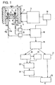
- Fig. 1 is a block diagram of a DSC apparatus that is one example of the present invention.
- reference numeral 1 is a silver heat sink having a section in an almost H-character form.
- the temperature of the heat sink 1 is measured by a thermocouple 2 for measuring furnace temperature so that a signal thereof is sent to an furnace temperature control circuit 3.
- An insulator-covered heater 4 is supplied with electric power based on an output of the furnace temperature control circuit 3 so that the heat sink 1 is controlled of temperature through heat conduction.
- the temperature control of the heat sink 1 employs a known PID control method wherein the heater 4 is supplied with output as electric power calculated, in the furnace temperature control circuit 3, of proportion, integration and differentiation on the difference between a temperature outputted from a function generator 16 depending on a desired temperature program and an output temperature of the furnace temperature measuring thermocouple 2.
- the heat sink 1 is fixed, at its central portion, with a heat conducting plate 6 of constantan (copper-nickel alloy) in a form that its center is fixed within the heat sink 1.
- the heat conducting plate 6 is formed, at its one end, with a sample section 6a in the form of a platform and, at the other end, with a reference section 6b in a symmetric form.
- the sample section 6a is placed with a sample 8 packed in an aluminum vessel 7, and the reference section 6b is placed with a vessel 7 packed with alumina powder 9. Also, the heat sink 1 is provided, at its top portion, with a lid 5 in an attachable and detachable form so that the vessel 7 can be put in and out.
- a thermocouple junction 10 is formed immediately beneath the sample section 6a which has a chromel wire 10a as a positive electrode and an alumel wire 10b as a negative electrode. At the junction 10 the sample 8 is measured of temperature according to an electromotive force of the chromel-alumel (K type) thermocouple.
- thermocouple junction 11 having a chromel wire 11a as a positive electrode and an alumel wire 11b as a negative electrode. This is provided for the purpose of keeping structural symmetry to the sample section 6a with heat leak taken into account.
- the alumina powder 9 as a reference is not directly measured of temperature by the junction 11.
- a chromel-constantan thermocouple with a junction 10 as a junction is formed between the constantan as a material of the heat conducting plate 6 and chromel wire 10a.
- a thermocouple of a similar kind is formed at the junction 11 .
- the voltage between the chromel wire 10a and the chromel wire 11a becomes so-called a differential heat signal representative of a temperature difference between both junctions based on an electromotive force of the chromel-constantan thermocouple.
- the chromel wire 10a and the alumel wire 10b are connected to the sample temperature measuring circuit 12.
- the sample temperature measuring circuit 12 measures, at the junction 10, a temperature of the sample 8 depending on a potential difference between the both wire 10a, 10b.
- the chromel wire 10a and the chromel wire 11a are connected to a DSC measuring circuit 13.
- the potential difference between the chromel wires 10a and 11a represents a temperature difference between the junctions 10 and 11 so that it reflects a temperature difference between the sample 8 and the reference alumina powder 9.
- the potential difference between 10a, 11a also represents heat flows respectively flowing from the sample 8 and the alumina powder 9 into the heat sink 1. That is, it is widely known as a principle of heat flux type DSC that it is possible to handle this potential difference as a differential heat flow signal (DSC signal) if it is appropriately amplified (in a manner taking as a coefficient a thermal resistance in heat flow detection).
- DSC signal differential heat flow signal
- sample temperature signal obtained at the sample temperature measuring circuit 12 and the DSC signal obtained at the DSC measuring circuit 13 are both supplied through an analog-digital converter (not shown) to a processor 18 where they are stored.
- the temperature of the heat sink 1 can be programmed as a temperature signal in a form of ramp function, with respect to time, and precisely controlled by the action of the furnace temperature control circuit 3 based on an output from a function generator 16 for generating a programmed temperature signal.
- the temperature of the sample 8 is controlled according to the heating speed programmed in the function generator 16.
- the function generator 16 generates the afore-said temperature program and at the same time connected to the processor 18 so that it sends an elapsing time after starting measurement as a time signal to the processor 18.
- the temperature signal from the temperature measuring circuit 12, and the DSC signal from the differential heat flow measuring circuit 13 are supplied to the processor 18, besides the time signal from the function generator 16.
- the series of signals are controlled as thermal analysis data.
- Thermal analysis data is sent from the processor 18 to a peak baseline separator 19 connected to the processor 18.
- a DSC signal of the thermal analysis data is separated into two components of a peak component and a baseline component.
- the peak component data is sent to a peak waveform analyzer 20 connected to the peak baseline separator 19, while the baseline component data is sent to a baseline amplifier 21.
- peaks are appropriately separated such that the data represented as overlapping of a plurality of peaks are represented as a single peak overlapping.
- the peak is determined originally as a single peak, no especial processing is performed on the data but for passing the data through the peak waveform analyzer 20.
- the peak waveform analyzer 20 is connected with a peak data integrator 22 to calculate peak integration data as a time integration for individual peak data after separation.
- the peak waveform analyzer 20 and the peak data integrator 22 are connected to an activation energy calculator 23.
- the activation energy calculator 23 calculates an activation energy for each DSC peak from the data of temperature, peak components and peak integration based on a well known method as a Freeman-Carroll method.
- the information of the separated DSC peak signal and its temperature range and an activation energy value corresponding to each DSC peak is sent to a peak shift calculator 24 connected to the activation energy calculator 23.
- the peak shift calculator 24 in accordance with Arrhenius rule representing a relationship between temperature and time of reaction occurring in the sample, there are calculated temperature deviations at each DSC peak point to be generated where measuring by varying the heating rate based on an activation energy value at each DSC peak to determine individual DSC peaks with the temperature shifted by the deviation amount.
- the height (magnitude) of the DSC peak signal is rated by multiplying by an appropriate coefficient so as to maintain the magnitude of the peak integration signal (i.e., in a manner saving a DSC peak are depicted by taking the horizontal coordinate as a time coordinate).
- the baseline amplifier 21 amplifies the magnitude of the baseline component so as to be proportional to the heating rate depending on variation in the heating rate.
- a data addition synthesizer 25 is connected to the peak shift calculator 24 and the baseline amplifier 21 so that added together at each temperature are the individual DSC peak data from the peak shift calculator 24 and the DSC baseline data from the baseline amplifier 21.
- the output of the data addition synthesizer 25 thus obtained lies as a presumption on a DSC signal to be obtained by varying the heating rate.
- a thermally stable reference substance e.g., an alumina powder 9 contained in an aluminum vessel 7 is placed on the reference section 6b together with its vessel.
- a sample contained in an aluminum vessel 7 to be subjected to DSC measurement is placed on the sample section 6a together with its vessel.
- a temperature program used for measurement is inputted to the function generator 16. The temperature program sets a start temperature, an end temperature, and a heating rate in the interval between both temperatures.
- An appropriate temperature program should be used in accordance with sample properties and measurement purposes.
- the typical example of temperature program includes a program to heat up from room temperature to 600 degrees at a rate of 10 degrees per minute. If a measurement is executed under this program, it takes about one hour for measurement.
- the measuring time can be shortened by increasing the heating rate.
- varying the heating rate will change the reaction temperature and separate reactions to a lesser extent. Consequently, it is more difficult to see the reactions.
- the heating rate used for actual thermal analysis is roughly from 5 degrees to 20 degrees per minute.
- the troubles can be eliminated by the measurement with increased heating rate due to the functions of the peak baseline separator 19 to the data addition synthesizer 25, and accordingly measurement is carried out using a temperature program a rate of 50 degrees per minute.
- the respective signals of lapse time, sample temperature and differential heat flow (DSC) in measurement are taken, as a set of thermal analysis data, at a predetermined sampling interval throughout the measurement into the processor 18 through a (not-shown) analog-digital converter.
- the thermal analysis data taken into the processor 18 is sent, after ending the measurement, to the peak baseline separator 19.
- the DSC signal is separated into a peak component and a baseline component by the following procedure.
- the peak component data thus obtained is sent to the peak waveform analyzer 20, while the baseline component data to the baseline amplifier 21.
- the peak waveform analyzer 20 first examined are the number of peaks contained in the peak component data signal and the manner of their overlapping. The number of peaks and how they overlap are examined by the following procedure:
- the peak data separated by the peak waveform analyzer 20 is each sent to the peak data integrator 22.
- the peak data is each integrated with respect to time based on the following [Equation 1].
- activation energy is calculated on the peaks separated by the peak waveform analyzer 20 based on the Freeman-Carroll method by using temperature, peak data and peak integration data.
- the number of the activation energy obtained agrees with the number of the peaks.
- the activation energies have values within every time range of the data and takes the form of a step function whose value varies across every peak boundaries.
- x is the amount of chemical structure that is created or reduced by the reaction
- t is time
- A is a frequency factor (constant)
- ⁇ E is an activation energy
- R is a gas constant
- T is an absolute temperature
- g is a function of x.
- T 2 1 / ⁇ (1/T 1 ) + (R/ ⁇ E) ⁇ In (B 1 /B 2 ) ⁇
- Equation 9 indicates that the point of temperature T1 in each peak signal waveform of DSC separated should be shifted to temperature T2 in order to convert thermal analysis data measured at a heating rate B1 into data about heating rate B2.
- the total DSC signal that should finally be obtained in the case of the measurement at the heating rate B2 can be estimated.
- the output signal in the DSC apparatus or DTA apparatus is accompanied by a particular signal delay due to thermal detection.
- Several methods are proposed for correcting such a signal delay based on a well-known deconvolution technique. When these techniques are applied to the output signal processing in the apparatus described in the embodiment, higher quality data can be obtained.
- a measurement can be completed in a time that is reduced by a factor of 5 using a DSC or DTA apparatus in accordance with the present invention by performing the measurement at an experimental heating rate of 50 degrees per minute, for example, and then converting data into data that would be obtained at a heating rate of 10 degrees/min.
- the measuring efficiency can be enhanced by the great reduction in the measuring time.
- the present invention is applicable, after measurement, to a simulation for a DSC (DTA) result in a case of changing a heating rate condition, it can be utilized for a purpose that more precise data analysis is made by selecting the experimental heating rate lower in order to reduce an effect of response delay due to heat flow measurement and converting into higher-rate heating data.
- DTA DSC
Landscapes
- Chemical & Material Sciences (AREA)
- Engineering & Computer Science (AREA)
- Chemical Kinetics & Catalysis (AREA)
- Combustion & Propulsion (AREA)
- Physics & Mathematics (AREA)
- Health & Medical Sciences (AREA)
- Life Sciences & Earth Sciences (AREA)
- Analytical Chemistry (AREA)
- Biochemistry (AREA)
- General Health & Medical Sciences (AREA)
- General Physics & Mathematics (AREA)
- Immunology (AREA)
- Pathology (AREA)
- Investigating Or Analyzing Materials Using Thermal Means (AREA)
Applications Claiming Priority (2)
| Application Number | Priority Date | Filing Date | Title |
|---|---|---|---|
| JP788198 | 1998-01-19 | ||
| JP00788198A JP3370592B2 (ja) | 1998-01-19 | 1998-01-19 | 示差熱分析装置 |
Publications (3)
| Publication Number | Publication Date |
|---|---|
| EP0930500A2 true EP0930500A2 (fr) | 1999-07-21 |
| EP0930500A3 EP0930500A3 (fr) | 2001-03-07 |
| EP0930500B1 EP0930500B1 (fr) | 2006-08-02 |
Family
ID=11677962
Family Applications (1)
| Application Number | Title | Priority Date | Filing Date |
|---|---|---|---|
| EP99300323A Expired - Lifetime EP0930500B1 (fr) | 1998-01-19 | 1999-01-19 | Analyseur thermique différentiel |
Country Status (4)
| Country | Link |
|---|---|
| US (1) | US6146012A (fr) |
| EP (1) | EP0930500B1 (fr) |
| JP (1) | JP3370592B2 (fr) |
| DE (1) | DE69932550T2 (fr) |
Cited By (1)
| Publication number | Priority date | Publication date | Assignee | Title |
|---|---|---|---|---|
| EP2848926A1 (fr) * | 2013-09-13 | 2015-03-18 | Netzsch Gerätebau GmbH | Système et méthode pour l'analyse en thermogravimétrie modulée |
Families Citing this family (24)
| Publication number | Priority date | Publication date | Assignee | Title |
|---|---|---|---|---|
| US6113261A (en) * | 1997-06-27 | 2000-09-05 | Ta Instruments, Inc. | Method and apparatus of modulated-temperature thermogravimetry |
| JP3274095B2 (ja) * | 1997-07-18 | 2002-04-15 | 富士通株式会社 | 加熱炉内の被加熱物の熱解析装置及びそれを用いたリフロー炉の制御装置並びにそのプログラムを記録したコンピュータ読み取り可能な記録媒体 |
| JP2964140B1 (ja) * | 1998-05-18 | 1999-10-18 | セイコーインスツルメンツ株式会社 | 熱分析装置 |
| DE69811890T2 (de) * | 1998-10-01 | 2003-11-06 | Mettler-Toledo Gmbh, Greifensee | Einzellenkalorimeter |
| JP3883724B2 (ja) * | 1999-01-18 | 2007-02-21 | エスアイアイ・ナノテクノロジー株式会社 | 熱機械測定装置および方法 |
| JP3242899B2 (ja) * | 1999-04-27 | 2001-12-25 | セイコーインスツルメンツ株式会社 | 熱分析装置 |
| US6561692B2 (en) | 2000-03-23 | 2003-05-13 | Ta Instruments-Waters Llc | Differential scanning calorimeter |
| US6431747B1 (en) * | 2000-03-23 | 2002-08-13 | Ta Instruments, Inc. | Heat flux differential scanning calorimeter sensor |
| US6428203B1 (en) * | 2000-03-23 | 2002-08-06 | Ta Instruments, Inc. | Power compensation differential scanning calorimeter |
| US6488406B2 (en) | 2000-03-23 | 2002-12-03 | Ta Instruments-Waters, Llc | Differential scanning calorimeter |
| JP2001305086A (ja) * | 2000-04-26 | 2001-10-31 | Seiko Instruments Inc | 熱分析装置 |
| US6843595B2 (en) * | 2001-01-26 | 2005-01-18 | Waters Investment Limited | Differential scanning calorimeter accounting for heat leakage |
| US6641300B1 (en) | 2001-01-29 | 2003-11-04 | Waters Investment, Ltd. | Differential scanning calorimeter |
| US6648504B2 (en) | 2002-03-01 | 2003-11-18 | Waters Investment Limited | System and method for calibrating contact thermal resistances in differential scanning calorimeters |
| DE10227182B4 (de) * | 2002-06-18 | 2013-01-31 | Mettler-Toledo Ag | Probenhalter für die Differenz-Thermoanalyse |
| US7371006B2 (en) * | 2004-02-10 | 2008-05-13 | Perkinelmer Las, Inc. | Differential scanning calorimeter (DSC) with temperature controlled furnace |
| US7775962B2 (en) * | 2005-08-10 | 2010-08-17 | The Regents Of The University Of California | Centrifuge with polymerizing energy source |
| JP4849961B2 (ja) * | 2006-06-05 | 2012-01-11 | エスアイアイ・ナノテクノロジー株式会社 | 熱分析装置 |
| JP4831487B2 (ja) * | 2006-12-21 | 2011-12-07 | エスアイアイ・ナノテクノロジー株式会社 | 示差走査熱量計 |
| CN103091364B (zh) * | 2013-01-30 | 2014-11-19 | 北京空间飞行器总体设计部 | 一种火工药剂高温环境适应性试验方法 |
| JP6530611B2 (ja) * | 2015-01-23 | 2019-06-12 | 株式会社日立ハイテクサイエンス | 熱分析データの処理方法および熱分析装置 |
| CN111610119A (zh) * | 2019-02-25 | 2020-09-01 | 中国石油天然气股份有限公司 | 原油活化能测定方法 |
| CN112051300B (zh) * | 2020-09-14 | 2022-12-06 | 广西大学 | 松香及其改性树脂储存温度的测定和计算方法 |
| CN114778597A (zh) * | 2022-03-31 | 2022-07-22 | 河南建筑材料研究设计院有限责任公司 | 一种具有滤光功能的隔热温差测试装置 |
Family Cites Families (10)
| Publication number | Priority date | Publication date | Assignee | Title |
|---|---|---|---|---|
| US3747396A (en) * | 1971-07-09 | 1973-07-24 | Perkin Elmer Corp | Linearizing circuit for a ramp generator in a differential scanning calorimeter |
| JPS5230495A (en) * | 1975-09-03 | 1977-03-08 | Rigaku Denki Kk | Thermal analysis apparatus |
| GB2075675A (en) * | 1980-03-25 | 1981-11-18 | Inst Cercetari Chim | Method and apparatus for the calorimetric study of composite materials |
| US4552465A (en) * | 1984-01-10 | 1985-11-12 | Aluminum Company Of America | Two-point spring loaded thermocouple probe with replaceable tips |
| HU194405B (en) * | 1985-05-10 | 1988-01-28 | Magyar Optikai Muevek | Temperature control system for testing thermic phase transformations |
| FR2642169B1 (fr) * | 1989-01-26 | 1992-02-07 | Solomat Partners Lp | Procede d'analyse des spectres de relaxation et des resonances dans les materiaux |
| US5439291C1 (en) * | 1992-03-02 | 2002-04-16 | Ta Instr Inc | Method and apparatus for ac differential thermal analysis |
| JP2909950B2 (ja) * | 1993-09-24 | 1999-06-23 | セイコーインスツルメンツ株式会社 | 熱分析装置 |
| EP0803061B1 (fr) * | 1994-06-01 | 2004-05-06 | Perkin-Elmer Corporation | Appareil et procede d'analyse diffentielle utilisant les composants de signaux imaginaires et reels |
| US5549387A (en) * | 1994-06-01 | 1996-08-27 | The Perkin-Elmer Corporation | Apparatus and method for differential analysis using real and imaginary signal components |
-
1998
- 1998-01-19 JP JP00788198A patent/JP3370592B2/ja not_active Expired - Fee Related
-
1999
- 1999-01-15 US US09/232,472 patent/US6146012A/en not_active Expired - Lifetime
- 1999-01-19 DE DE69932550T patent/DE69932550T2/de not_active Expired - Lifetime
- 1999-01-19 EP EP99300323A patent/EP0930500B1/fr not_active Expired - Lifetime
Cited By (2)
| Publication number | Priority date | Publication date | Assignee | Title |
|---|---|---|---|---|
| EP2848926A1 (fr) * | 2013-09-13 | 2015-03-18 | Netzsch Gerätebau GmbH | Système et méthode pour l'analyse en thermogravimétrie modulée |
| US9389194B2 (en) | 2013-09-13 | 2016-07-12 | Netzsch-Geraetebau Gmbh | System and method for analysis in modulated thermogravimetry |
Also Published As
| Publication number | Publication date |
|---|---|
| EP0930500B1 (fr) | 2006-08-02 |
| JPH11201924A (ja) | 1999-07-30 |
| US6146012A (en) | 2000-11-14 |
| JP3370592B2 (ja) | 2003-01-27 |
| DE69932550D1 (de) | 2006-09-14 |
| EP0930500A3 (fr) | 2001-03-07 |
| DE69932550T2 (de) | 2007-08-02 |
Similar Documents
| Publication | Publication Date | Title |
|---|---|---|
| EP0930500B1 (fr) | Analyseur thermique différentiel | |
| US5599104A (en) | Thermal analysis instrument | |
| Mraw | Mathematical treatment of heat flow in differential scanning calorimetry and differential thermal analysis instruments | |
| US5711604A (en) | Method for measuring the coefficient of heat conductivity of a sample | |
| US5439291A (en) | Method and apparatus for AC Differential thermal analysis | |
| US20020041619A1 (en) | Method for measuring absolute value of thermal conductivity | |
| Schick et al. | Differential scanning calorimetry and differential thermal analysis | |
| EP0919806B1 (fr) | Analyseur thermique rapide | |
| JP2004012462A (ja) | 物質の熱的調査方法及び装置 | |
| Gustavsson et al. | Thermal effusivity measurements of insulating liquids using microsized hot strip probes | |
| JPH07260663A (ja) | 熱重量測定における発生ガス分析方法 | |
| GB2075675A (en) | Method and apparatus for the calorimetric study of composite materials | |
| Corsan | Axial heat flow methods of thermal conductivity measurement for good conducting materials | |
| JP2909922B2 (ja) | 熱機械的分析の温度補正方法 | |
| JP2002181751A (ja) | 示差走査熱量計 | |
| Lerchner et al. | Ambient perturbation reduction in microsized calorimetric systems | |
| JPH06265492A (ja) | 熱分析装置 | |
| RU2129708C1 (ru) | Способ проверки соответствия сигналов термоэлектрических преобразователей действительным значениям температуры | |
| Isalgue et al. | Non-differential conduction calorimeter, a tool to study the after quench behaviour in shape memory alloys | |
| Razouk et al. | Toward new high temperature reference materials for calorimetry and thermal analysis | |
| de Oliveira et al. | Design of a double-gradient scanner apparatus to assess the uncertainty component associated with inhomogeneity in flexible wire thermocouples | |
| EP1402249B1 (fr) | Procede de mesure de la valeur absolue de la conductivite thermique | |
| SU1057829A1 (ru) | Устройство дл определени локальных коэффициентов теплоотдачи между поверхностью раздела фаз и движущейс средой | |
| SU953528A1 (ru) | Устройство дл термодиэлектрических исследований | |
| JP2004279074A (ja) | 熱機械分析装置 |
Legal Events
| Date | Code | Title | Description |
|---|---|---|---|
| PUAI | Public reference made under article 153(3) epc to a published international application that has entered the european phase |
Free format text: ORIGINAL CODE: 0009012 |
|
| AK | Designated contracting states |
Kind code of ref document: A2 Designated state(s): DE GB |
|
| AX | Request for extension of the european patent |
Free format text: AL;LT;LV;MK;RO;SI |
|
| PUAL | Search report despatched |
Free format text: ORIGINAL CODE: 0009013 |
|
| AK | Designated contracting states |
Kind code of ref document: A3 Designated state(s): AT BE CH CY DE DK ES FI FR GB GR IE IT LI LU MC NL PT SE |
|
| AX | Request for extension of the european patent |
Free format text: AL;LT;LV;MK;RO;SI |
|
| 17P | Request for examination filed |
Effective date: 20010806 |
|
| AKX | Designation fees paid |
Free format text: DE GB |
|
| 17Q | First examination report despatched |
Effective date: 20041029 |
|
| RAP1 | Party data changed (applicant data changed or rights of an application transferred) |
Owner name: SII NANOTECHNOLOGY INC. |
|
| GRAP | Despatch of communication of intention to grant a patent |
Free format text: ORIGINAL CODE: EPIDOSNIGR1 |
|
| GRAS | Grant fee paid |
Free format text: ORIGINAL CODE: EPIDOSNIGR3 |
|
| GRAA | (expected) grant |
Free format text: ORIGINAL CODE: 0009210 |
|
| AK | Designated contracting states |
Kind code of ref document: B1 Designated state(s): DE GB |
|
| REG | Reference to a national code |
Ref country code: GB Ref legal event code: FG4D |
|
| REF | Corresponds to: |
Ref document number: 69932550 Country of ref document: DE Date of ref document: 20060914 Kind code of ref document: P |
|
| PLBE | No opposition filed within time limit |
Free format text: ORIGINAL CODE: 0009261 |
|
| STAA | Information on the status of an ep patent application or granted ep patent |
Free format text: STATUS: NO OPPOSITION FILED WITHIN TIME LIMIT |
|
| 26N | No opposition filed |
Effective date: 20070503 |
|
| GBPC | Gb: european patent ceased through non-payment of renewal fee |
Effective date: 20070119 |
|
| PG25 | Lapsed in a contracting state [announced via postgrant information from national office to epo] |
Ref country code: GB Free format text: LAPSE BECAUSE OF NON-PAYMENT OF DUE FEES Effective date: 20070119 |
|
| REG | Reference to a national code |
Ref country code: DE Ref legal event code: R082 Ref document number: 69932550 Country of ref document: DE Representative=s name: PATENTANWAELTE WEICKMANN & WEICKMANN, DE |
|
| REG | Reference to a national code |
Ref country code: DE Ref legal event code: R082 Ref document number: 69932550 Country of ref document: DE Representative=s name: WEICKMANN & WEICKMANN PATENT- UND RECHTSANWAEL, DE Effective date: 20141014 Ref country code: DE Ref legal event code: R082 Ref document number: 69932550 Country of ref document: DE Representative=s name: WEICKMANN & WEICKMANN PATENTANWAELTE - RECHTSA, DE Effective date: 20141014 Ref country code: DE Ref legal event code: R082 Ref document number: 69932550 Country of ref document: DE Representative=s name: PATENTANWAELTE WEICKMANN & WEICKMANN, DE Effective date: 20141014 Ref country code: DE Ref legal event code: R081 Ref document number: 69932550 Country of ref document: DE Owner name: HITACHI HIGH-TECH SCIENCE CORPORATION, JP Free format text: FORMER OWNER: SII NANOTECHNOLOGY INC., CHIBA, JP Effective date: 20141014 |
|
| PGFP | Annual fee paid to national office [announced via postgrant information from national office to epo] |
Ref country code: DE Payment date: 20170110 Year of fee payment: 19 |
|
| REG | Reference to a national code |
Ref country code: DE Ref legal event code: R119 Ref document number: 69932550 Country of ref document: DE |
|
| PG25 | Lapsed in a contracting state [announced via postgrant information from national office to epo] |
Ref country code: DE Free format text: LAPSE BECAUSE OF NON-PAYMENT OF DUE FEES Effective date: 20180801 |