EP0930608A1 - Vocoder mit effizienter fehlertoleranter Kodierung mittels Anregungsvektoren - Google Patents
Vocoder mit effizienter fehlertoleranter Kodierung mittels Anregungsvektoren Download PDFInfo
- Publication number
- EP0930608A1 EP0930608A1 EP98310200A EP98310200A EP0930608A1 EP 0930608 A1 EP0930608 A1 EP 0930608A1 EP 98310200 A EP98310200 A EP 98310200A EP 98310200 A EP98310200 A EP 98310200A EP 0930608 A1 EP0930608 A1 EP 0930608A1
- Authority
- EP
- European Patent Office
- Prior art keywords
- excitation pulse
- pulses
- pulse
- excitation
- sets
- Prior art date
- Legal status (The legal status is an assumption and is not a legal conclusion. Google has not performed a legal analysis and makes no representation as to the accuracy of the status listed.)
- Withdrawn
Links
Images


Classifications
-
- G—PHYSICS
- G10—MUSICAL INSTRUMENTS; ACOUSTICS
- G10L—SPEECH ANALYSIS TECHNIQUES OR SPEECH SYNTHESIS; SPEECH RECOGNITION; SPEECH OR VOICE PROCESSING TECHNIQUES; SPEECH OR AUDIO CODING OR DECODING
- G10L19/00—Speech or audio signals analysis-synthesis techniques for redundancy reduction, e.g. in vocoders; Coding or decoding of speech or audio signals, using source filter models or psychoacoustic analysis
- G10L19/04—Speech or audio signals analysis-synthesis techniques for redundancy reduction, e.g. in vocoders; Coding or decoding of speech or audio signals, using source filter models or psychoacoustic analysis using predictive techniques
- G10L19/08—Determination or coding of the excitation function; Determination or coding of the long-term prediction parameters
- G10L19/12—Determination or coding of the excitation function; Determination or coding of the long-term prediction parameters the excitation function being a code excitation, e.g. in code excited linear prediction [CELP] vocoders
-
- G—PHYSICS
- G10—MUSICAL INSTRUMENTS; ACOUSTICS
- G10L—SPEECH ANALYSIS TECHNIQUES OR SPEECH SYNTHESIS; SPEECH RECOGNITION; SPEECH OR VOICE PROCESSING TECHNIQUES; SPEECH OR AUDIO CODING OR DECODING
- G10L19/00—Speech or audio signals analysis-synthesis techniques for redundancy reduction, e.g. in vocoders; Coding or decoding of speech or audio signals, using source filter models or psychoacoustic analysis
- G10L19/04—Speech or audio signals analysis-synthesis techniques for redundancy reduction, e.g. in vocoders; Coding or decoding of speech or audio signals, using source filter models or psychoacoustic analysis using predictive techniques
- G10L19/06—Determination or coding of the spectral characteristics, e.g. of the short-term prediction coefficients
Definitions
- the present invention relates to communications; more specifically, voice encoding.
- a voice encoder is used to encode voice signals so as to minimise the amount of bandwidth that is used for transmitting over communication channels. It is important to minimize the amount of bandwidth used per communication channel so as to maximize the number of channels available within a given range of spectrum.
- Many vocoders are known as code excited linear predictive (CELP) vocoders.
- CELP vocoders which model the fixed codebook contribution to the filter excitation as a series of pulses use a inefficient encoding scheme that is sensitive to bit errors.
- An encoding scheme that is wasteful of precious bandwidth and is sensitive to bit errors is particularly undesirable in a error-prone communication channel such as a wireless communication channel.
- the encoding process involves representing a series of excitation pulses or an excitation vector as a series of bits referred to as a fixed index.
- the fixed index is used by a vocoder at a receiver to reproduce the excitation pulses which are then used to excite a speech model and thereby reproduce speech.
- Prior vocoders represent these pulses using 3-1/2 or more bits per pulse. Additionally, prior vocoders are sensitive to communication channel induced errors because a single bit error may produce effort in up to two pulses.
- FIG. 1 illustrates a series of pulses that are to be represented by a fixed index.
- the fixed index specifies which ten of the forty possible predetermined positions are occupied by a pulse and the sign of each pulse.
- An inefficient coding scheme is illustrated by the table of FIG. 2.
- the vocoder is limited to using excitation vectors that are composed of a series of pulses that are permitted by the possible combinations specified by the table.
- FIG. 2 illustrates a fixed index table where two pulses are associated with each row of the table.
- each of pulses I 0 and I 5 are restricted to one of eight positions; namely, positions 0, 5, 10, 15, 20, 25, 30 and 35. Likewise, each remaining row specifies the possible positions that may be assigned to each pulse of the pulse pair associated with that row. It should be noted that specifying one of eight positions for each pulse requires three bits for each pulse. Additionally, a sign is specified for each pulse. In this prior art system, one bit is used to specify the sign of the first pulse of each pulse pair in each row. The sign of the second pulse in each pulse pair is specified by the position of that pulse. If the second pulse has a position that is smaller than the first pulse's position, the sign of the second pulse is opposite to that of the first pulse, otherwise the signs of the pulses are the same.
- the present invention provides a CELP vocoder that efficiently encodes an excitation vector in a way that is less sensitive to single bit errors.
- Each of the pulses composing the excitation vector are limited to one of four predetermined positions. As a result, only three bits are required to encode each pulse (two bits for position and one sign bit) and, in addition, a single bit error only produces a error in one pulse.
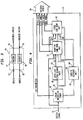
- FIG. 3 illustrates a block diagram of a typical vocoder.
- Vocoder 10 receives digitized speech on input 12.
- the digitized speech is an analog speech signal that has been passed through an analog to digitized converter, and has been broken into flames where each flame is typically on the order of 20 milliseconds.
- the signal at input 12 is passed to encoder section 14 which encodes the speech so as decrease the amount of bandwidth used to transmit the speech.
- the encoded speech is made available at output 16.
- the encoded speech is received by the decode section of a similar vocoder at the other end of a communication channel.
- the decoder at the other end of the communication channel is similar or identical to the decoder portion of vocoder 10.
- Encoded speech is received by vocoder 10 through input 18, and is passed to decoder section 20.
- Decoder section 20 uses the encoded signals received from the transmitting vocoder to produce digitized speech at output 22.
- Vocoders are well known in the communications arts. For example, vocoders are described in "Speech and audio coding for wireless and network applications," edited by Bishnu S. Atal, Vladimir Cuperman, and Allen Gersho, 1993, by Kluwer Academic Publishers. Vocoders are widely available and manufactured by companies such as Qualcomm Incorporated of San Diego, California, and Lucent Technologies Inc., of Murray Hill, New Jersey.
- FIG. 4 illustrates the major functions of encoder 14 of vocoder 10.
- a digitized speech signal is received at input 12, and is passed to linear predictive coder 40.
- Linear predictive coder 40 performs a linear predictive analysis of the incoming speech once per flame. Linear predictive analysis is well known in the art and produces a linear predictive synthesis model of the vocal tract based on the input speech signal. The linear predictive parameters or coefficients describing this model are transmitted as part of the encoded speech signal through output 16.
- Coder 40 uses this model to produce a residual speech signal which represents the excitation that the model uses to reproduce the input speech signal.
- the residual speech signal is made available at output 42.
- the residual speech from output 42 is provided to input 48 of open-loop pitch search unit 50, to an input of adaptive codebook unit 72 and to fixed codebook unit 82.
- Impulse response unit 60 receives the linear predictive parameters from coder 40 and generates the impulse response of the model generated in coder 40. This impulse response is used in the adaptive and fixed codebook units.
- Open loop pitch search unit 50 uses the residual speech signal from coder 40 to model its pitch and provides a pitch, or what is commonly called the pitch period or pitch delay signal, at output 52.
- the pitch delay signal from output 52 and the impulse response signal from output 64 of impulse response unit 60 are received by input 70 of adaptive codebook unit 72.
- Adaptive codebook unit 72 produces a pitch gain output and a pitch index output which become part of encoded speech output 16 of vocoder 10.
- Output 74 of adaptive codebook 72 also provides the pitch gain and pitch index signals to input 80 of fixed codebook unit 82. Additionally, adaptive codebook 72 provides an excitation signal and a adaptive codebook target signal to input 80.
- the adaptive codebook 72 produces its outputs using the digitised speech signal from input 12 and the residual speech signal produced by linear predictive coder 40.
- Adaptive codebook 72 uses the digitized speech signal and linear predictive coder 40's residual speech signal to form an adaptive codebook target signal.
- the adaptive codebook target signal is used as an input to fixed codebook 82, and as a input to a computation that produces the pitch gain, pitch index and excitation outputs of adaptive codebook unit 72.
- the adaptive codebook target signal, the pitch delay signal from open loop pitch search unit 50, and the impulse response from impulse response unit 60 are used to produced the pitch index, the pitch gain and excitation signals which are passed to fixed codebook unit 82.
- the manner in which these signals are computed is well known in the vocoder art.
- Fixed codebook 82 uses the inputs received from input 80 to produce a fixed gain output and a fixed index output which are used as part of the encoded speech at output 16.
- the fixed codebook unit attempts to model the stocastic part of the linear predictive coder 40's residual speech signal.
- a target for a fixed codebook search is produced by determining a fixed codebook error or the difference between the current adaptive codebook target signal and the residual speech signal from linear predictive coder 40.
- the fixed codebook error is well known in the art and is described in telecommunications standards as the mean square error between a weighted speech signal and a weighted synthesis speech signal. These standards are published by groups such as the International Telecommunication Union, the European Telecommunications Standards Institute, and the Telecommunications Industry Association.
- the fixed codebook search produces the fixed gain and fixed index that minimizes the fixed codebook error or the mean square of the error.
- the fixed index describes a set of excitation pulses.
- the fixed index is obtained by searching for a set of excitation pulses that minimize the fixed codebook error, however, the search for a set of excitation pulses is limited to valid sets of excitation pulses defined by the fixed codebook's fixed index table.
- the fixed index table limits the number of possible positions that each pulse may occupy.
- the manner in which the fixed gain and fixed index signals are computed using the outputs from adaptive codebook unit 72 are well known in the vocoder art.
- FIG. 5 illustrates a functional block diagram of decoder 20 of vocoder 10.
- Encoded speech signals are received at input 18 of encoder 20.
- the encoded speech signals are received by decoder 100.
- Decoder 100 produces fixed and adaptive code vectors corresponding to the fixed index and pitch index signals, respectively. These code vectors are passed to the excitation construction portion of unit 110 along with the pitch gain and the fixed gain signals.
- the pitch gain signal is used to scale the adaptive vector which was produced using the pitch index signal
- the fixed gain signal is used to scale the fixed vector which was obtained using the fixed index signal.
- Decoder 100 passes the linear predictive code parameters to the filter or model synthesis section of unit 110.
- Unit 110 then uses the scaled vectors to excite the filter that is synthesized using the linear predictive coefficients produced by linear predictive coder 40, and produces an output signal which is representative of the digitized speech originally received at input 12.
- post filter 120 may be used to shape the spectrum of the digitized speech signal that is produced at output 20.
- one of fixed codebook 82's outputs is a fixed index.
- a fixed index is produced four times per frame (once per subframe), which is every 5 msec for a system using 20 msec frames.
- the fixed index specifies an excitation vector or a series of excitation pulses, where the bits of the fixed index describe the position and sign of the pulses. As mentioned earlier, these excitation pulses are used as inputs to a speech model in a receiving vocoder.
- FIG. 6 illustrates a fixed index table used for specifying the possible predetermined positions of the excitation pulses composing a valid excitation vector.
- Each pulse is limited to one of four predetermined positions and therefore only requires two bits to specify a position.
- a third bit is used to specify a sign. For example, if ten pulses are to be specified, ten rows each having four possible positions are included in the table. In this example, pulse I 0 may occupy positions 0, 10, 20 or 30. And likewise, each of the other pulses may occupy one of the possible positions specified in its row. In this example, only thirty bits are required to specify the position and sign of ten pulses (3 bits/pulse) because two bits per pulse specify position and one bit per pulse specifies a sign.
- FIG. 7 illustrates a fixed index table used for specifying the possible predetermined positions of five pulses where each pulse may occupy only one of four positions.
- FIG. 8 illustrates a fixed index table specifying the possible predetermined positions of the pulses in a three pulse excitation vector where the excitation pulses specified by the last two rows are limited to three possible predetermined locations each. It is also possible to use a fixed index table that limits one or more excitation pulses to two possible predetermined locations each.
- the schemes of FIGS. 6, 7 and 8 may be applied to excitation vectors having any number of pulses and the number of possible predetermined positions that each pulse may occupy may be limited to four or less.
- the functional block diagrams can be implemented in various forms. Each block can be implemented individually using microprocessors or microcomputers, or they can be implemented using a single microprocessor or microcomputer. It is also possible to implement each or all of the functional blocks using programmable digital signal processing devices or specialized devices received from the aforementioned manufacturers or other semiconductor manufacturers.
Landscapes
- Engineering & Computer Science (AREA)
- Computational Linguistics (AREA)
- Signal Processing (AREA)
- Health & Medical Sciences (AREA)
- Audiology, Speech & Language Pathology (AREA)
- Human Computer Interaction (AREA)
- Physics & Mathematics (AREA)
- Acoustics & Sound (AREA)
- Multimedia (AREA)
- Compression, Expansion, Code Conversion, And Decoders (AREA)
Applications Claiming Priority (2)
| Application Number | Priority Date | Filing Date | Title |
|---|---|---|---|
| US6676 | 1993-01-15 | ||
| US667698A | 1998-01-13 | 1998-01-13 |
Publications (1)
| Publication Number | Publication Date |
|---|---|
| EP0930608A1 true EP0930608A1 (de) | 1999-07-21 |
Family
ID=21722053
Family Applications (1)
| Application Number | Title | Priority Date | Filing Date |
|---|---|---|---|
| EP98310200A Withdrawn EP0930608A1 (de) | 1998-01-13 | 1998-12-11 | Vocoder mit effizienter fehlertoleranter Kodierung mittels Anregungsvektoren |
Country Status (5)
| Country | Link |
|---|---|
| EP (1) | EP0930608A1 (de) |
| KR (1) | KR19990067850A (de) |
| CN (1) | CN1239796A (de) |
| BR (1) | BR9900019A (de) |
| CA (1) | CA2254620A1 (de) |
Citations (4)
| Publication number | Priority date | Publication date | Assignee | Title |
|---|---|---|---|---|
| US4932061A (en) * | 1985-03-22 | 1990-06-05 | U.S. Philips Corporation | Multi-pulse excitation linear-predictive speech coder |
| US5193140A (en) * | 1989-05-11 | 1993-03-09 | Telefonaktiebolaget L M Ericsson | Excitation pulse positioning method in a linear predictive speech coder |
| FR2729245A1 (fr) * | 1995-01-06 | 1996-07-12 | Lamblin Claude | Procede de codage de parole a prediction lineaire et excitation par codes algebriques |
| EP0749111A2 (de) * | 1995-06-14 | 1996-12-18 | AT&T IPM Corp. | Kodebuch-Suchverfahren für die Sprachverarbeitung |
-
1998
- 1998-11-30 CA CA002254620A patent/CA2254620A1/en not_active Abandoned
- 1998-12-11 EP EP98310200A patent/EP0930608A1/de not_active Withdrawn
-
1999
- 1999-01-07 BR BR9900019-9A patent/BR9900019A/pt not_active Application Discontinuation
- 1999-01-12 KR KR1019990000524A patent/KR19990067850A/ko not_active Withdrawn
- 1999-01-12 CN CN99101060A patent/CN1239796A/zh active Pending
Patent Citations (4)
| Publication number | Priority date | Publication date | Assignee | Title |
|---|---|---|---|---|
| US4932061A (en) * | 1985-03-22 | 1990-06-05 | U.S. Philips Corporation | Multi-pulse excitation linear-predictive speech coder |
| US5193140A (en) * | 1989-05-11 | 1993-03-09 | Telefonaktiebolaget L M Ericsson | Excitation pulse positioning method in a linear predictive speech coder |
| FR2729245A1 (fr) * | 1995-01-06 | 1996-07-12 | Lamblin Claude | Procede de codage de parole a prediction lineaire et excitation par codes algebriques |
| EP0749111A2 (de) * | 1995-06-14 | 1996-12-18 | AT&T IPM Corp. | Kodebuch-Suchverfahren für die Sprachverarbeitung |
Non-Patent Citations (2)
| Title |
|---|
| BAKAMIDIS S G ET AL: "A REDUCED COMPLEXITY MULTIPULSE COMPRESSION SYSTEM", SPEECH COMMUNICATION, vol. 10, no. 2, 1 June 1991 (1991-06-01), pages 171 - 178, XP000208004 * |
| DELPRAT M ET AL: "17 A 6 KBPS REGULAR PULSE CELP CODER FOR MOBILE RADIO COMMUNICATIONS", ADVANCES IN SPEECH CODING, VANCOUVER, SEPT. 5 - 8, 1989, 1 January 1991 (1991-01-01), ATAL B S;CUPERMAN V; GERSHO A, pages 179 - 188, XP000419273 * |
Also Published As
| Publication number | Publication date |
|---|---|
| BR9900019A (pt) | 2000-01-04 |
| CA2254620A1 (en) | 1999-07-13 |
| CN1239796A (zh) | 1999-12-29 |
| KR19990067850A (ko) | 1999-08-25 |
Similar Documents
| Publication | Publication Date | Title |
|---|---|---|
| EP1202251B1 (de) | Transkodierer zur Vermeidung einer Kaskadenkodierung von Sprachsignalen | |
| US7280959B2 (en) | Indexing pulse positions and signs in algebraic codebooks for coding of wideband signals | |
| EP0409239B1 (de) | Verfahren zur Sprachkodierung und -dekodierung | |
| US6470313B1 (en) | Speech coding | |
| US7792679B2 (en) | Optimized multiple coding method | |
| EP0815554A1 (de) | Linear-prädiktiver analyse-durch-synthese sprachkodierer | |
| EP2037451A1 (de) | Verfahren zur Verbesserung der Codierungseffizienz eines Audiosignals | |
| JPH05197400A (ja) | 低ビット・レート・ボコーダ手段および方法 | |
| US6847929B2 (en) | Algebraic codebook system and method | |
| JPH11259100A (ja) | 励起ベクトルの符号化方法 | |
| US5253269A (en) | Delta-coded lag information for use in a speech coder | |
| EP1020848A2 (de) | Verfahren zur Übertragung von zusätzlichen informationen in einem Vokoder-Datenstrom | |
| US6687667B1 (en) | Method for quantizing speech coder parameters | |
| EP0556354B1 (de) | Fehlerschutz für vielfachmodensprachkodierer | |
| EP0863500A2 (de) | Verfahren zur Sprachkodierung und -dekodierung mit veränderlicher Datenrate | |
| JP3063668B2 (ja) | 音声符号化装置及び復号装置 | |
| CA2373479C (en) | Device, method and program for encoding/decoding of speech with function of encoding silent period | |
| EP0930608A1 (de) | Vocoder mit effizienter fehlertoleranter Kodierung mittels Anregungsvektoren | |
| US20030055633A1 (en) | Method and device for coding speech in analysis-by-synthesis speech coders | |
| AU1127699A (en) | Vocoder with efficient, fault tolerant excitation vector encoding | |
| AU679980B2 (en) | Process for conditioning data, especially coded voice signal parameters | |
| JP3065638B2 (ja) | 音声符号化方式 | |
| KR100389898B1 (ko) | 음성부호화에 있어서 선스펙트럼쌍 계수의 양자화 방법 | |
| JPH06118999A (ja) | 音声のパラメータ情報符号化法 | |
| MOHAMMADI et al. | Efficient Coding of the Short-Term Speech Spectrum with Two-Step Vector Quantization Methods |
Legal Events
| Date | Code | Title | Description |
|---|---|---|---|
| PUAI | Public reference made under article 153(3) epc to a published international application that has entered the european phase |
Free format text: ORIGINAL CODE: 0009012 |
|
| 17P | Request for examination filed |
Effective date: 19990105 |
|
| AK | Designated contracting states |
Kind code of ref document: A1 Designated state(s): AT BE CH CY DE DK ES FI FR GB GR IE IT LI LU MC NL PT SE |
|
| AX | Request for extension of the european patent |
Free format text: AL;LT;LV;MK;RO;SI |
|
| 17Q | First examination report despatched |
Effective date: 19990701 |
|
| AKX | Designation fees paid | ||
| STAA | Information on the status of an ep patent application or granted ep patent |
Free format text: STATUS: THE APPLICATION IS DEEMED TO BE WITHDRAWN |
|
| REG | Reference to a national code |
Ref country code: DE Ref legal event code: 8566 |
|
| 18D | Application deemed to be withdrawn |
Effective date: 19991112 |