EP0930703A2 - Oberflächenwellenfilter mit verbesserter Frequenzcharakteristik - Google Patents
Oberflächenwellenfilter mit verbesserter Frequenzcharakteristik Download PDFInfo
- Publication number
- EP0930703A2 EP0930703A2 EP99100368A EP99100368A EP0930703A2 EP 0930703 A2 EP0930703 A2 EP 0930703A2 EP 99100368 A EP99100368 A EP 99100368A EP 99100368 A EP99100368 A EP 99100368A EP 0930703 A2 EP0930703 A2 EP 0930703A2
- Authority
- EP
- European Patent Office
- Prior art keywords
- surface acoustic
- acoustic wave
- idts
- wave filter
- electrode
- Prior art date
- Legal status (The legal status is an assumption and is not a legal conclusion. Google has not performed a legal analysis and makes no representation as to the accuracy of the status listed.)
- Withdrawn
Links
Images


Classifications
-
- H—ELECTRICITY
- H03—ELECTRONIC CIRCUITRY
- H03H—IMPEDANCE NETWORKS, e.g. RESONANT CIRCUITS; RESONATORS
- H03H9/00—Networks comprising electromechanical or electro-acoustic elements; Electromechanical resonators
- H03H9/46—Filters
- H03H9/64—Filters using surface acoustic waves
- H03H9/6423—Means for obtaining a particular transfer characteristic
- H03H9/6433—Coupled resonator filters
-
- H—ELECTRICITY
- H03—ELECTRONIC CIRCUITRY
- H03H—IMPEDANCE NETWORKS, e.g. RESONANT CIRCUITS; RESONATORS
- H03H9/00—Networks comprising electromechanical or electro-acoustic elements; Electromechanical resonators
- H03H9/25—Constructional features of resonators using surface acoustic waves
Definitions
- the present invention relates to a surface acoustic wave filter in which IDTs (Inter Digital Transducer) on an input side and on an output side each made of a plurality of electrode digits are formed on a piezoelectric substrate with a spacing interposed therebetween.
- IDTs Inter Digital Transducer
- Fig. 1 is a plan view showing an example of a conventional surface acoustic wave filter.
- This surface acoustic wave filter 102 has IDTs 106, 108 on an input side and on an output side, which are surface acoustic waves transducers, formed with a spacing interposed therebetween on piezoelectric substrate 104 made of crystal and the like.
- the width of each electrode digit of each of IDTs 106, 108 is ⁇ /4 where ⁇ is the wavelength of the surface acoustic wave during resonance.
- One electrode 114 of IDTs 106, 108 are connected to input terminal 116 and output terminal 118 the other electrodes 120 are both grounded.
- IDT 106 when an alternating signal is supplied from input terminal 116, IDT 106 causes a surface acoustic wave to be excited on piezoelectric substrate 104.
- the wave is propagated in a direction orthogonal to the extending direction of each electrode digit 112 constituting IDT 106, forms a standing wave while repeating multiple reflection between IDTS 106 and 108, and is received in IDT 108 and then outputted from output terminal 118 as an electric signal.
- Surface acoustic wave filter 102 having such construction as described above is also referred to as a vertical mode resonator type surface acoustic wave filter since the surface acoustic wave is propagated in the vertical direction and the resonance of the modes distributed in the same direction as the propagated direction is utilized.
- Fig. 2 is a graph showing the frequency characteristic of surface acoustic wave filter 102.
- the horizontal axis represents the frequency and the vertical axis represents the attenuation factor, respectively.
- An ideal characteristic for surface acoustic wave filter 102 which is a band-pass filter is to pass signals only in the pass-band near the center frequency f. However, signals are actually passed in some degree even at a point away from the center frequency, which phenomenon appears as a spurious signal in the frequency characteristic.
- a typical spurious signal 122 occurs in a region higher than the center frequency, which causes a reduction in the amount of attenuation out of the band and a deterioration in the frequency characteristic as a band-pass filter.
- N ⁇ 0.55 is satisfied where ⁇ is a reflection coefficient of an electrode digit and N is the total number of pairs of the electrode digits constituting IDTs on an input side and on an output side
- fH ⁇ -17.5W+210 is satisfied where W(wavelength) is the aperture width of the surface acoustic wave transmission path formed of the IDTs on the input side and on the output side, f(Hz) is the center frequency of the filter, and H(m) is the thickness of the electrode digits.
- the reflection coefficient ⁇ of the electrode digit and the total number N of the pairs of the electrode digits of the IDT are set to satisfy N ⁇ 0.55 and the aperture width W of the surface acoustic wave transmission path, the center frequency f of the filter, and the thickness H of the electrode digits are set to satisfy fH ⁇ -17.5W+210, bulk mode transformation in the IDT is increased. As a result, the spurious signal typical of the vertical mode resonator type surface acoustic wave filter is suppressed, thereby improving the frequency characteristic as a band-pass filter.
- surface acoustic wave filter 2 is a vertical mode resonator type surface acoustic wave filter serving as a band-pass filter and includes IDTs 4, 6 on an input side and on an output side.
- IDTs 4, 6 are formed by depositing a thin film made of aluminum or an alloy of aluminum on ST cut crystal substrate 8 (hereinafter also referred to as piezoelectric substrate 8) and disposed on piezoelectric substrate 8 with a spacing interposed therebetween.
- Each of IDTs 4, 6 is made of plurality of pairs of inter digital shape electrodes.
- the width of each electrode digit 12 is ⁇ /4 where ⁇ is the wavelength of the surface acoustic wave during resonance.
- One electrodes 14 of IDTs 4, 6 are connected to input terminal 16 and output terminal 18, respectively, and the other electrodes 20 are both grounded.
- a reflection coefficient per electrode digit i.e. acoustic impedance discontinuous coefficient
- N the total number of the pairs of the electrode digits constituting IDTs 4, 6 on the input side and on the output side
- the setting the product of the total number N of the pairs of the electrode digits and the reflection coefficient ⁇ to be 0.55 or more is equivalent to the setting the reflection coefficient of the overall surface waveguide path to be 1.5 or more.
- This value can be realized with the existing technology in a vertical mode resonator type surface acoustic wave filter having a usual constitution such as surface acoustic wave filter 2 of this embodiment.
- the aperture width W(wavelength) of the surface acoustic wave transmission path formed of IDTs 4, 6, the center frequency f of the filter, and the thickness H(m) of the electrode digits are set to satisfy the equation (2).
- the aperture width W(wavelength) indicates that the aperture width is W times the wavelength of the surface acoustic wave in a resonant state. fH ⁇ -17.5W+210
- the aperture width W of the surface acoustic wave transmission path is shorter than that of a conventional surface acoustic wave filter when the center frequency f and the thickness H of the electrode digits are those as conventional.
- surface acoustic wave filter 2 constituted as described above is the same as that of conventional surface acoustic wave filter 10. Specifically, when an alternating signal is supplied from input terminal 16, IDT 4 causes the surface acoustic wave to be excited on piezoelectric substrate 8. The wave is propagated in a direction orthogonal to the extending direction of each electrode digit 12 constituting IDT, forms a standing wave while repeating multiple reflection between IDTs 4 and 6, and is received in IDT 6 and then outputted from output terminal 18 as an electric signal.
- Fig. 4 is a graph showing the frequency characteristic of surface acoustic wave filter 2, in which the horizontal axis represents the frequency and the vertical axis represents the attenuation factor, respectively.
- spurious signal 22 typical of a vertical mode resonator type surface acoustic wave filter occurring on the higher side than the center frequency f is greatly reduced, improving the frequency characteristic as a pass-band filter.
- dotted line 24 represents the level of spurious signal 122 in the case of the conventional surface acoustic wave filter 102 (Fig. 2).
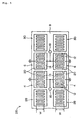
- FIG. 5 there is shown a surface acoustic wave filter according to a second embodiment of the present invention.
- elements identical to those in Fig. 3 are designated by the same reference numerals and symbols and will not be described in detail herein.
- a pair of grating reflectors 28, 30 are formed on piezoelectric substrate 8 to sandwich IDTs 4, 6 on an input side and on an output side therebetween. Furthermore, two sets each made of IDTs 4, 6 and a pair of grating reflectors 28, 30 are formed on piezoelectric substrate 8. These grating reflectors 28, 30 are formed by depositing a thin film made of aluminum or an alloy of aluminum on piezoelectric substrate 8 in this embodiment similarly to IDTS 4, 6.
- the aperture width of the surface acoustic wave transmission path formed of respective grating reflectors 28, 30 is substantially coincident with the aperture width W of the surface acoustic wave transmission path made of IDTs 4, 6.
- Electrodes 14 of the respective IDTs 4 are both connected to input terminal 16 and electrodes 14 of the respective IDTs 6 are both connected to output terminal 18.
- electrodes 20 of the respective IDTs 4 and electrodes 20 of the respective IDTs 6 are both grounded.
- the product N ⁇ of the total number N of the pairs of electrode digits 12 and a reflection coefficient ⁇ per electrode digit is set to be 3.9
- the product fH of the center frequency f and the thickness H of electrode digits 12 is set to be 70
- the aperture width W of the surface acoustic waveguide path is set to be 5.5(wavelength), respectively.
- each IDT 4 when an alternating signal is supplied from input terminal 16, each IDT 4 causes a surface acoustic wave to be excited on piezoelectric substrate 8.
- the wave is propagated in a direction orthogonal to the extending direction of each electrode digit 12 constituting IDT 4, forms a standing wave while repeating multiple reflection between IDTs 4 and 6 and grating reflectors 28, 30, and is received in each IDT 6 and then outputted from output terminal 18 as an electric signal.
- Fig. 6 is a graph showing the frequency characteristic of the surface acoustic wave filter of the second embodiment.
- Fig. 7 is a graph showing the frequency characteristics of a conventional surface acoustic wave filter.
- the horizontal axis represents the frequency and the vertical axis represents the attenuation factor.
- the aperture width of the surface acoustic wave transmission path is set to be 11(wavelength) (i.e. 5.5 ⁇ 2) to obtain the same condition as that of surface acoustic wave filter 26 of the second embodiment.
- the parallel connection of two IDTs 4, 6 in this embodiment enables input and output impedance to be suppressed as compared with the first embodiment, so that the spurious signals can be suppressed without increasing the input and output impedance.
- Fig. 8 is a graph showing the result of the investigation.
- the horizontal axis represents the aperture width W and the vertical axis represents the product of the center frequency f and the thickness H of the electrode digits.
- the O marks and X marks in the graph respectively correspond to the surface acoustic wave filters made.
- the O marks indicate that the level of the spurious signal was suppressed by 3 dB or more as compared with conventional case (i.e. suppressed to 1/2 or less) and the X marks indicate that such a suppression effect was not obtained.
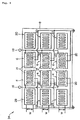
- Fig. 9 is a plan view showing a surface acoustic wave filter according to a third embodiment of the present invention.
- elements identical to those in Fig. 5 are designated by the same reference numerals and symbols.
- This surface acoustic wave filter 34 differs from surface acoustic wave filter 26 according to the second embodiment in that a further set of IDTs 4, 6 and a pair of grating reflectors 28, 30 are added in the surface acoustic wave filter 34.
- Electrodes 14 of respective IDTs 4 are all connected to input terminal 16 and electrodes 14 of respective IDTs 6 are all connected to output terminal 18. Also, electrodes 20 of respective IDTs 4, 6 are all grounded.
- the parallel connection of three IDTs 4, 6 in this embodiment enables input and output impedance to be further suppressed as compared with the second embodiment, so that the spurious signal can be suppressed without increasing the input and output impedance.
- piezoelectric substrate 8 is made of the ST cut crystal substrate in the afore mentioned embodiments, lithium tantalate (LiTaO3), lithium niobate (LiNbO3), lithium tetraborate (Li2B4O7) and the like may be used for piezoelectric substrate 8 without being limited to the crystal substrate. Similar effects can be obtained by using those materials.
Landscapes
- Physics & Mathematics (AREA)
- Acoustics & Sound (AREA)
- Surface Acoustic Wave Elements And Circuit Networks Thereof (AREA)
Applications Claiming Priority (2)
| Application Number | Priority Date | Filing Date | Title |
|---|---|---|---|
| JP10020313A JP3137064B2 (ja) | 1998-01-16 | 1998-01-16 | 弾性表面波フィルタ |
| JP2031398 | 1998-01-16 |
Publications (2)
| Publication Number | Publication Date |
|---|---|
| EP0930703A2 true EP0930703A2 (de) | 1999-07-21 |
| EP0930703A3 EP0930703A3 (de) | 2000-12-27 |
Family
ID=12023656
Family Applications (1)
| Application Number | Title | Priority Date | Filing Date |
|---|---|---|---|
| EP99100368A Withdrawn EP0930703A3 (de) | 1998-01-16 | 1999-01-15 | Oberflächenwellenfilter mit verbesserter Frequenzcharakteristik |
Country Status (3)
| Country | Link |
|---|---|
| US (1) | US6049260A (de) |
| EP (1) | EP0930703A3 (de) |
| JP (1) | JP3137064B2 (de) |
Families Citing this family (8)
| Publication number | Priority date | Publication date | Assignee | Title |
|---|---|---|---|---|
| KR100476913B1 (ko) * | 2000-06-27 | 2005-03-17 | 가부시끼가이샤 도시바 | 탄성표면파 소자 |
| US6806619B2 (en) | 2001-10-16 | 2004-10-19 | Matsushita Electric Industrial Co., Ltd. | Interdigital transducer, surface acoustic wave filter, and radio communication apparatus |
| JP4668178B2 (ja) * | 2004-04-28 | 2011-04-13 | パナソニック株式会社 | 弾性表面波共振子 |
| JP6668213B2 (ja) * | 2015-10-01 | 2020-03-18 | スカイワークスフィルターソリューションズジャパン株式会社 | 分波器と通信機器 |
| US10404234B2 (en) | 2016-09-02 | 2019-09-03 | Skyworks Filter Solutions Japan Co., Ltd. | Filter device with phase compensation, and electronic devices including same |
| US10476482B2 (en) | 2016-11-29 | 2019-11-12 | Skyworks Solutions, Inc. | Filters including loop circuits for phase cancellation |
| TWI834694B (zh) | 2018-07-18 | 2024-03-11 | 美商天工方案公司 | 具有積體取消電路之薄膜塊體聲諧振器濾波器 |
| US12580550B2 (en) | 2022-12-20 | 2026-03-17 | Skyworks Solutions, Inc. | Bulk acoustic wave filter circuit having phase cancelling circuit |
Family Cites Families (14)
| Publication number | Priority date | Publication date | Assignee | Title |
|---|---|---|---|---|
| JPH0773177B2 (ja) * | 1984-12-17 | 1995-08-02 | 株式会社東芝 | 弾性表面波共振子 |
| JPS63194406A (ja) * | 1987-02-09 | 1988-08-11 | Hitachi Ltd | 弾性表面波共振子 |
| JPH071859B2 (ja) * | 1988-03-11 | 1995-01-11 | 国際電気株式会社 | 弾性表面波フィルタ |
| JPH03296316A (ja) * | 1990-04-13 | 1991-12-27 | Nikko Kyodo Co Ltd | 弾性表面波共振子フィルタ |
| JPH04259109A (ja) * | 1991-02-13 | 1992-09-14 | Seiko Epson Corp | 2ポートsaw共振子 |
| JP3160918B2 (ja) * | 1991-02-20 | 2001-04-25 | セイコーエプソン株式会社 | 弾性表面波フィルタ |
| JP3126416B2 (ja) * | 1991-06-26 | 2001-01-22 | キンセキ株式会社 | 弾性表面波装置 |
| JPH05121996A (ja) * | 1991-10-30 | 1993-05-18 | Nikko Kyodo Co Ltd | 弾性表面波フイルタ |
| JP3001350B2 (ja) * | 1993-05-19 | 2000-01-24 | 日本電気株式会社 | 弾性表面波フィルタ |
| US5365138A (en) * | 1993-12-02 | 1994-11-15 | Northern Telecom Limited | Double mode surface wave resonators |
| GB2289181B (en) * | 1994-04-25 | 1998-08-12 | Advanced Saw Prod Sa | Saw filter |
| WO1996010293A1 (en) * | 1994-09-29 | 1996-04-04 | Seiko Epson Corporation | Saw device |
| US5568001A (en) * | 1994-11-25 | 1996-10-22 | Motorola, Inc. | Saw device having acoustic elements with diverse mass loading and method for forming same |
| JP3224202B2 (ja) * | 1996-11-28 | 2001-10-29 | 富士通株式会社 | 弾性表面波装置 |
-
1998
- 1998-01-16 JP JP10020313A patent/JP3137064B2/ja not_active Expired - Fee Related
-
1999
- 1999-01-15 US US09/231,657 patent/US6049260A/en not_active Expired - Lifetime
- 1999-01-15 EP EP99100368A patent/EP0930703A3/de not_active Withdrawn
Also Published As
| Publication number | Publication date |
|---|---|
| JPH11205081A (ja) | 1999-07-30 |
| JP3137064B2 (ja) | 2001-02-19 |
| EP0930703A3 (de) | 2000-12-27 |
| US6049260A (en) | 2000-04-11 |
Similar Documents
| Publication | Publication Date | Title |
|---|---|---|
| EP0633660B1 (de) | Akustisches Oberflächenwellenfilter | |
| US7573178B2 (en) | Acoustic wave device, resonator and filter | |
| US7741931B2 (en) | Acoustic wave device, resonator and filter | |
| US5977686A (en) | Surface acoustic wave filter | |
| EP1244212B1 (de) | Akustische Oberflächenwellenanordnung und Kommunikationssystem | |
| US7646266B2 (en) | Surface acoustic wave resonator and surface acoustic wave filter using the same | |
| JPH08265087A (ja) | 弾性表面波フィルタ | |
| JP2014160888A (ja) | 弾性波共振器とこれを用いた弾性波フィルタおよびアンテナ共用器 | |
| US6650206B2 (en) | Surface acoustic wave filter and communication apparatus with the same | |
| US7042313B2 (en) | Surface acoustic wave device and communication device using the same | |
| US6049260A (en) | Surface acoustic wave filter having parameters optimized to suppress spurious signals | |
| US6297713B1 (en) | Surface acoustic wave device with split electrodes and outermost electrodes of a different width than the split electrodes | |
| US6720847B2 (en) | Longitudinally-coupled resonator surface acoustic wave filter and communication apparatus using the same | |
| JP4821079B2 (ja) | 弾性表面波用のくし型電極部、弾性表面波装置、通信装置 | |
| EP0763889B1 (de) | Akustisches oberflächenwellenfilter | |
| KR19980019102A (ko) | 탄성표면파 공진자 필터(Surface acoustic wave resonator filter) | |
| US20200313651A1 (en) | Multiplexer | |
| JP4053038B2 (ja) | 弾性表面波装置 | |
| US6147574A (en) | Unidirectional surface acoustic wave transducer and transversal-type saw filter having the same | |
| EP0800270B1 (de) | Akustischer Oberflächenwellenfilter | |
| US6781282B1 (en) | Longitudinally coupled resonator-type surface acoustic wave device | |
| JPH08316773A (ja) | 表面弾性波装置 | |
| JP2748009B2 (ja) | 表面弾性波共振子フィルタ | |
| JP2010245738A (ja) | Sawフィルター | |
| JPH04265009A (ja) | 弾性表面波フィルタ |
Legal Events
| Date | Code | Title | Description |
|---|---|---|---|
| PUAI | Public reference made under article 153(3) epc to a published international application that has entered the european phase |
Free format text: ORIGINAL CODE: 0009012 |
|
| AK | Designated contracting states |
Kind code of ref document: A2 Designated state(s): DE FR GB |
|
| AX | Request for extension of the european patent |
Free format text: AL;LT;LV;MK;RO;SI |
|
| PUAL | Search report despatched |
Free format text: ORIGINAL CODE: 0009013 |
|
| AK | Designated contracting states |
Kind code of ref document: A3 Designated state(s): AT BE CH CY DE DK ES FI FR GB GR IE IT LI LU MC NL PT SE |
|
| AX | Request for extension of the european patent |
Free format text: AL;LT;LV;MK;RO;SI |
|
| 17P | Request for examination filed |
Effective date: 20001116 |
|
| AKX | Designation fees paid |
Free format text: DE FR GB |
|
| RAP1 | Party data changed (applicant data changed or rights of an application transferred) |
Owner name: NRS TECHNOLOGIES INC. |
|
| RAP1 | Party data changed (applicant data changed or rights of an application transferred) |
Owner name: NIHON DEMPA KOGYO CO., LTD. |
|
| 17Q | First examination report despatched |
Effective date: 20071102 |
|
| STAA | Information on the status of an ep patent application or granted ep patent |
Free format text: STATUS: THE APPLICATION IS DEEMED TO BE WITHDRAWN |
|
| 18D | Application deemed to be withdrawn |
Effective date: 20110802 |