EP0931453B1 - Verfahren und Vorrichtung zum Übertragen eines durch eine Entwässerungskolonne hergestellten Molkenblockes zu einem Käsefass - Google Patents
Verfahren und Vorrichtung zum Übertragen eines durch eine Entwässerungskolonne hergestellten Molkenblockes zu einem Käsefass Download PDFInfo
- Publication number
- EP0931453B1 EP0931453B1 EP99200238A EP99200238A EP0931453B1 EP 0931453 B1 EP0931453 B1 EP 0931453B1 EP 99200238 A EP99200238 A EP 99200238A EP 99200238 A EP99200238 A EP 99200238A EP 0931453 B1 EP0931453 B1 EP 0931453B1
- Authority
- EP
- European Patent Office
- Prior art keywords
- vessel
- transfer
- cheese
- curd
- curd block
- Prior art date
- Legal status (The legal status is an assumption and is not a legal conclusion. Google has not performed a legal analysis and makes no representation as to the accuracy of the status listed.)
- Expired - Lifetime
Links
Images


Classifications
-
- A—HUMAN NECESSITIES
- A01—AGRICULTURE; FORESTRY; ANIMAL HUSBANDRY; HUNTING; TRAPPING; FISHING
- A01J—MANUFACTURE OF DAIRY PRODUCTS
- A01J25/00—Cheese-making
- A01J25/11—Separating whey from curds; Washing the curds
- A01J25/111—Separating whey from curds; Washing the curds by continuous separation
- A01J25/112—Separating whey from curds; Washing the curds by continuous separation in cylinders
-
- A—HUMAN NECESSITIES
- A01—AGRICULTURE; FORESTRY; ANIMAL HUSBANDRY; HUNTING; TRAPPING; FISHING
- A01J—MANUFACTURE OF DAIRY PRODUCTS
- A01J25/00—Cheese-making
- A01J25/12—Forming the cheese
Definitions
- the invention relates to a process for transferring a curd block obtained from a drainage column to a cheese vessel, which comprises periodically lowering a curd column present in the drainage column into a case by means of a metering cylinder provided with a supporting member, cutting off a curd block at the bottom side of the curd column, and moving the case with the curd block therein sidewards.
- the invention further relates to an apparatus for using the process.
- a bottomless case is used.
- the supporting member with the cut-off curd block thereon is lowered to just below the lower edge of the case.
- the case with the curd block just formed therein is moved sidewards over the supporting member to above a gate plate.
- the gate plate opens when a cheese vessel is present below the gate plate.
- the curd block falls into the cheese vessel and can then be conveyed on for further operations, such as a pressing operation.
- a process of the above type is characterized according to the invention in that the case is a transfer vessel with a bottom that can be moved up and down; that the transfer vessel, after being filled with a curd block, is moved sidewards into a transfer position in a station.
- An apparatus for transferring a curd block obtained from a drainage column to a cheese vessel which comprises periodically lowering a curd column present in a drainage column into a case by means of a supporting member; cutting off a curd block at the bottom side of the curd column, and moving the case with the curd block therein sidewards, is characterized according to the invention in that the case is a transfer vessel with a bottom that can be moved up and down by means of a metering cylinder; that means are provided for moving a filled transfer vessel sidewards into a transfer position in a station.
- Fig. 1 diagrammatically shows an example of a known curd drainage apparatus 1.
- the apparatus shown has a drainage column 2, into which, in operation, a whey-curd mixture is fed at the top side.
- a curd column is formed in the drainage column 2.
- the whey can flow off via a perforated wall or perforated wall portions.
- a guillotine blade 3 which is operated by a cylinder 4, and by means of which a curd block is cut from the curd column at regular times.
- a supporting platform 6 is moved up by means of a cylinder 5 until the height of the blade 3 (Fig. 2A).
- the curd column while supported by the supporting platform, can be lowered by means of a suitable control of the cylinder 5.
- the curd column then sinks into a bottomless case 7, also referred to as sliding cartridge (Fig. 2C).
- the supporting platform is still at a small distance above the lowest position indicated by 8.
- the lowermost part of the curd column is cut off by means of the blade 3 (Fig. 2D).
- the supporting platform with the curd block thereon is brought into the lowest position (Fig. 2E).
- the sliding cartridge 7 is moved sidewards by means of a cylinder 10 (in the Figures to the right) (Fig. 2F).
- the curd block 9 thus slides over the piston onto a gate plate 11.
- the gate plate opens and the curd block falls into the cheese vessel.
- the sliding cartridge 7 is then withdrawn by the cylinder 10, while the filled cheese vessel 12 is discharged (Fig. 2G). Subsequently, the supporting platform moves up again (Fig. 2H), and the cycle can be repeated.
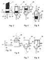
- Figs. 3 through 8 illustrate a first example of a process and apparatus according to the invention. It is observed that drainage columns are known in various embodiments. The invention is not limited to the use with one specific type of drainage column or drainage apparatus.
- Fig. 3 shows a curd block 9 cut from a curd column 30, received within a transfer vessel 31 with a bottom 32 that can be moved up and down by means of a cylinder 5, in a similar manner as described above for the known technique.
- the transfer vessel 31 unlike the above-described case or sliding cartridge, has a bottom 32, which, true, can be moved up and down like the supporting member 6, but which in the lowest position remains coupled to the transfer vessel, in the sense that the bottom, together with the rest of the vessel and the curd block contained therein, can be moved from the piston 33 of the cylinder 5 and sidewards over a supporting surface 34, as indicated by an arrow 35 in Fig. 3.
- the bottom side of the curd block now does not itself slide over a supporting surface and is therefore not damaged.
- the transfer vessel may have perforated or unperforated walls and/or a perforated or unperforated bottom.
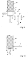
- the walls may further be smooth at the inner side or be provided with grooves. If desired, the walls may be provided at the lower side with means for preventing the bottom from falling out of the vessel. To this end, the walls could be provided e.g . with a narrow inwardly directed flange, as indicated by 40 in Fig. 9, on which the bottom 32 rests.
- the bottom may be provided with a circumferential shoulder 41 so as to form a smooth bottom side of the transfer vessel. However, the bottom may also be loose in the transfer vessel without being connected to the transfer vessel. It is important that the curd block is moved while lying on the bottom.
- the transfer vessel filled with a curd block is slid according to the invention into a reversing device 36.
- the reversing device 36 comprises a cylinder 37, which can act on the bottom 32 of the vessel, when the vessel is in a transfer position on a platform 38 of the reversing device, as shown in the right-hand part of Fig. 3. In the transfer position the transfer vessel 31 is above the cylinder 37 and below a reversed cheese vessel 39.
- the bottom 32 of the vessel 31 is now moved up by the cylinder 37 until the curd block 9 is completely or largely in the reversed cheese vessel 39, as shown in Fig. 4.
- the complete reversing device 36 is now rotated about a horizontal axis through 180°, as diagrammatically indicated by 43 with a curved arrow 44.
- the reversed position of the reversing device 36 is shown in Fig. 5.
- the curd block already begins to slide into the cheese vessel 39 after a rotation through 90° or more.
- the curd block completely sinks into the cheese vessel which is now in the normal position and can be discharged as indicated by an arrow 45 in Fig. 5.
- the piston may be connectable to the bottom by vacuum or mechanically.
- the piston may be provided e.g . with a suction cup that can be energized by reduced pressure or e.g . with parts of a bayonet catch, which cooperate with counterparts at the bottom.
- the bottom e.g . with lateral projections or the like, which prevent the bottom from falling out of the cheese vessel.
- the reversing device can be rotated into the starting position again.
- the bottom is then also moved again to the lower side of the transfer vessel by the cylinder 37. This may take place during and/or preceding and/or following the rotating-back movement.
- the bottom is withdrawn first (Fig. 6).
- Fig. 7 shows the reversing device 36 in the rotated-back position, in which the transfer vessel is in the usual position again. From the position shown in Fig. 7 the transfer vessel can be slid back by known per se means, not shown, to under the drainage column, whether or not via a bypass and/or a cleaning station. Subsequently, the reversing device 36 is provided again with a reversed cheese vessel 39 (Fig. 8), and the cycle can be repeated.
- the transfer vessel 31 must be temporarily coupled to the reversing device in order not to fall out of the reversing device in the reversed position.
- the cheese vessel 39 must be temporarily coupled to the reversing device.
- the reversing device may be provided with mechanical clamping means or with clamping means operating by vacuum. Also, use could be made of e.g . flanges at the transfer vessel and/or the reversing vessel, which engage the platform 38 or the carrier 47 for the cheese vessels under strips or the like.
- the reversing device may be arranged to transfer the contents of more than one transfer vessel simultaneously to a corresponding number of cheese vessels.
- Figs. 9 through 12 diagrammatically show a second example of a process and apparatus according to the invention.
- Fig. 9 diagrammatically shows the lowermost end of a drainage column 2 of a curd drainage apparatus.
- the drainage column contains a curd column 50.
- the curd column 50 rests on a guillotine blade 3, which closes the drainage column 2 and can be moved forward and backward in the manner indicated by an arrow 51 to close or release the drainage column and to cut off the lowermost part of a curd column 50 sunk from the drainage column, in a similar manner as described above.
- Fig. 9 the situation is such that the guillotine blade is in the closed position and that an empty transfer vessel 52 is present under the guillotine blade.
- the movable bottom 53 is moved up in the usual manner by means of a cylinder 5.
- the guillotine blade can be withdrawn, as soon as the drainage process of the curd column 50 has meanwhile made sufficient progress.
- the curd column 50 is supported by the bottom 53, which then sinks in the known manner (Fig. 10) until a cheese block of the desired height can be cut off.
- the guillotine blade is then brought into the closed position again, in which a cheese block 55 is cut off and the bottom 53 sinks further until it is at the height of the lower edge of the transfer vessel, as shown in Fig. 11.
- the transfer vessel 52 may then be moved sidewards to above a cheese vessel 54.
- the bottom 53 is supported by the piston 57, which then sinks, as indicated by an arrow 58, until the bottom 53 and the cheese block 55 are in the cheese vessel 54 and the situation shown in Fig. 12 has been realized.
- the filled cheese vessel is discharged by means of suitable discharge means (not shown) and an empty cheese vessel 54 conveyed into the position of the filled cheese vessel shown in Fig. 12.
- the movable bottom 53 is moved up by means of the cylinder 56 until a level corresponding to the lower side of the transfer vessel which is still (or again) in the place shown in Fig.
- the cheese vessels have a bottom that can be moved up and down, while the transfer vessel has no bottom of its own.
- the bottoms of the cheese vessels that can be moved up and down each time function as a temporary bottom for the transfer vessel.
- the temporary bottom can move sidewards with the transfer vessel.
- the movable bottom 53 is indicated by broken lines in the position in which the movable bottom cooperates with the transfer vessel. In the position indicated by full lines, the bottom 53 forms the bottom of the cheese vessel 54.
- diagrammatically shown at 56 is a cylinder with piston 57 for moving the bottom up and down.
- the bottom 52 must be able to pass the lower edge of the transfer vessel without hindrance.
- the cheese vessels 54 may be arranged in a manner such that the bottom 53 can be supported at the level of the lower edge of the cheese vessel.
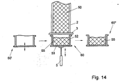
- Fig. 14 shows a drainage column 2 with a curd column 50 therein.
- a case 52 with a bottom 53 that can be moved up and down.
- the case 52 is not a part of a transfer vessel, but the case forms the side wall of a cheese vessel 60 which has a movable bottom 53.
- an empty cheese vessel 60' Positioned to the left of the cheese vessel 60 is an empty cheese vessel 60', which can take the place of the cheese vessel 60, as soon as the cheese vessel 60 has been moved from under the drainage column, e.g. into the position indicated at 60".
- a difference between a transfer vessel and a cheese vessel is that the cheese in a cheese vessel is subjected to a subsequent treatment, e.g . is pressed, that from a structural viewpoint a cheese vessel therefore must comply with more stringent requirements than a transfer vessel.
- the cheese vessels can be supplied with a supply conveyor and discharged with a discharge conveyor.
- push cylinders may be provided, similar to e.g . the cylinder 10 of Fig. 9, to place the cheese vessels under the drainage column and/or move them from under the drainage column.
- an intermittently driven continuous conveyor provided that the conveyor offers possibilities, e.g . openings in the conveyor surface, to allow the cylinder 5 to cooperate with the movable bottoms of the cheese vessels.
Landscapes
- Life Sciences & Earth Sciences (AREA)
- Animal Husbandry (AREA)
- Environmental Sciences (AREA)
- Dairy Products (AREA)
- Beans For Foods Or Fodder (AREA)
- Noodles (AREA)
Claims (27)
- Verfahren zum Übertragen eines aus einer Entwässerungskolonne erhaltenen Molkeblockes zu einem Käsefass, wobei das Verfahren das periodische Absenken einer in der Entwässerungskolonne vorhandenen Molkesäule in einen Behälter mittels eines Aufnahmeelementes, das Abschneiden eines Molkeblockes auf der Unterseite der Molkesäule, und das Seitwärtsbewegen des Behälters mit dem darin befindlichen Molkeblock aufweist,
gekennzeichnet, durch die Verwendung eines Aufnahmeelementes, welches einen Boden aufweist, der aufwärts und abwärts bewegt werden kann, welches mit dem Behälter derart zusammenwirkt, dass der Behälter nach der Füllung mit dem Molkeblock seitwärts bewegt werden kann, während der Molkeblock auf dem beweglichen Boden während der Bewegung verbleibt. - Verfahren nach Anspruch 1,
dadurch gekennzeichnet, dass der Behälter ein Übertragungsfass mit einem Boden ist, der aufwärts und abwärts bewegt werden kann und das Übertragungsfass nach der Füllung mit dem Molkeblock seitwärts in eine Übertragungsposition in einer Übertragungsstation bewegt wird, wobei der Molkeblock während der Bewegung auf dem beweglichen Boden verbleibt. - Verfahren nach Anspruch 2,
dadurch gekennzeichnet,dass die Übertragungsstation eine Umkehrstation ist, unddass in der Umkehrstation oberhalb der Übertragungsposition des Übertragungsfasses ein Käsefass in der Umkehrposition platziert ist,dass der Boden des Übertragungsfasses aufwärts bewegt wird bis der Molkeblock sich wenigstens teilweise in das Käsefass erstreckt,dass anschließend die Umkehrstation um ihre horizontale Achse gedreht wird, bis das Käsefass in der Normalstellung ist, worauf danach dass Käsefass entladen wird, unddass die Umkehrstation und der Boden des Übertragungsfasses wieder in die Startposition zurückgeführt werden, unddass letztlich das Übertragungsfass aus der Umkehrstation entfernt wird. - Verfahren nach Anspruch 2 oder 3,
dadurch gekennzeichnet, dass das Übertragungsfass zu einer Entwässerungskolonne mittels eines Nebenweges aus der Umkehrstation zurückgeführt wird. - Verfahren nach Anspruch 2,
dadurch gekennzeichnet,dass in der Übertragungsstation der auf dem beweglichen Boden liegende Molkeblock zu einem bereiten Käsefass übertragen wird, unddass das Käsefass mit dem darin auf dem beweglichen Boden liegenden Molkeblock dann aus der Übertragungsstation entlassen wird und das Übertragungsfass dann zur Entwässerungskolonne zurückgeführt wird. - Verfahren nach Anspruch 5,
dadurch gekennzeichnet, dass der bewegliche Boden zum Übertragen des Molkeblockes aus dem Übertragungsfass zu einem Käsefass abwärts aus dem Übertragungsfass in ein bodenfreies Käsefass bewegt wird, das sich unter dem Übertragungsfass befindet. - Verfahren nach Anspruch 1,
dadurch gekennzeichnet, dass der verwendete Behälter ein Käsefass mit einem beweglichen Boden ist, welches mit einem Molkeblock direkt unter der Entwässerungskolonne gefüllt ist, wobei das Käsefass einen Teil einer Anzahl von ähnlichen Käsefässern bildet, die aufeinanderfolgend zu einer Entwässerungskolonne zugeführt werden und welche nach der Füllung mit einem Molkeblock jeweils mittels geeigneter Fördereinrichtungen zu wenigstens einer Übertragungsstation zur weiteren Verarbeitung des Molkeblockes befördert werden, wobei der Molkeblock stets von dem beweglichen Boden des Käsefasses unterstützt verbleibt. - Vorrichtung zur Übertragung eines aus einer Entwässerungskolonne erhaltenen Molkeblocks zu einem Käsefass, welche das periodische Absenken einer in der Entwässerungskolonne vorhandenen Molkesäule in einen Behälter mittels eines Unterstützungselementes, das Abschneiden eines Molkeblockes von der Unterseite der Molkesäule, und das Seitwärtsbewegen des Behälters mit dem darin befindlichen Molkeblock aufweist,
dadurch gekennzeichnet,dass das Aufnahmeelement einen Boden aufweist, der mittels eines Messzylinders aufwärts und abwärts bewegt werden kann, unddass eine Einrichtung zum Seitwärtsbewegen eines gefüllten Behälters zusammen mit dem beweglichen Boden und einem darauf liegenden Molkeblock vorgesehen ist. - Vorrichtung nach Anspruch 8,
dadurch gekennzeichnet,dass der Behälter ein Übertragungsfass mit einem Boden ist, der aufwärts und abwärts bewegt werden kann unddass die Einrichtung zum Seitwärtsbewegen angeordnet ist, um den Behälter zusammen mit dem beweglichen Boden und einem darauf liegenden Molkeblock seitwärts in eine Übertragungsposition in einer Übertragungsstation zu bewegen, die wenigstens eine Übertragungsposition aufweist. - Vorrichtung nach Anspruch 9,
dadurch gekennzeichnet,dass die Übertragungsstation eine Umkehrstation ist, welche eine Einrichtung zum Platzieren eines Käsefasses in der Umkehrposition oberhalb der Übertragungsposition aufweist,dass die Umkehrstation außerdem eine Einrichtung aufweist, um den Boden des Übertragungsfasses mit einem Molkeblock darauf aufwärts zu bewegen, bis der Molkeblock wenigstens teilweise sich in das Käsefass erstreckt, unddass eine Rotationseinrichtung vorgesehen ist, um die Umkehrstation in die Umkehrposition mit dem Käsefass unten und dem Übertragungsfass darüber zu bringen, so dass der Molkeblock in das Käsefass gleiten kann. - Vorrichtung nach Anspruch 10,
dadurch gekennzeichnet, dass die Einrichtung zum Aufwärtsbewegen des Bodens des Übertragungsfasses einen in der Umkehrstation befestigten Zylinder mit einem Kolben aufweist, der auf den Boden des Übertragungsfasses wirkt. - Vorrichtung nach Anspruch 11,
dadurch gekennzeichnet, dass der Kolben eine Kopplungseinrichtung zum Bewirken eines temporären Koppelns mit dem Boden des Übertragungsfasses aufweist. - Vorrichtung nach Anspruch 12,
dadurch gekennzeichnet, dass die Kopplungseinrichtung mittels Vakuum arbeitet. - Vorrichtung nach Anspruch 12,
dadurch gekennzeichnet, dass die Kopplungseinrichtung eine temporäre mechanische Kopplung bewirkt. - Vorrichtung nach Anspruch 14,
dadurch gekennzeichnet, dass die Kopplungseinrichtung einen Bajonettverschluss bewirkt. - Vorrichtung nach einem der Ansprüche 10 bis 15,
dadurch gekennzeichnet, dass die Umkehrstation zum Drehen um eine horizontale Achse angeordnet ist. - Vorrichtung nach einem der Ansprüche 10 bis 16,
dadurch gekennzeichnet, dass die Umkehrstation eine Rückhalteeinrichtung für ein Käsefass und für ein Übertragungsfass aufweist. - Vorrichtung nach Anspruch 17,
dadurch gekennzeichnet, dass die Rückhalteeinrichtung eine Klemmeinrichtung aufweist. - Vorrichtung nach Anspruch 17 oder 18,
dadurch gekennzeichnet, dass die Rückhalteeinrichtung schienenähnliche Elemente aufweist, die um Flansche eines Käsefasses und/oder eines Übertragungsfasses greifen können. - Vorrichtung nach Anspruch 9,
dadurch gekennzeichnet, dass eine Übertragungseinrichtung zum Entfernen des beweglichen Bodens mit dem daraufliegenden Molkeblock von einem Übertragungsfass und zum Platzieren in einem Käsefass angeordnet ist. - Vorrichtung nach Anspruch 20,
dadurch gekennzeichnet, dass die Übertragungseinrichtung einen Zylinder aufweist, der mit einem Kolben versehen ist, wobei der Zylinder angeordnet ist, um den beweglichen Boden zu stützen und um ihn von dem Übertragungsfass in ein Käsefass herunter zu bewegen, das unter dem Übertragungsfass platziert ist. - Vorrichtung nach Anspruch 21,
dadurch gekennzeichnet, dass der bewegliche Boden nach der Übertragung zu einem Käsefass den Boden des Käsefasses bildet. - Vorrichtung zum Bilden von Molkenblöcken und zum Entladen derselben in Käsefässer, aufweisend eine Trocknungseinrichtung mit einer oder mehreren Entwässerungskolonnen, welche jeweils eine oder mehrere Entwässerungsröhren aufweisen,
gekennzeichnet durch eine Vorrichtung zum Übertragen von Molkenblöcken nach einem der Ansprüche 8 bis 22. - Vorrichtung nach Anspruch 23,
dadurch gekennzeichnet, dass ein Nebenweg zum Zurückführen geleerter Übertragungsfässer vorgesehen ist. - Vorrichtung nach Anspruch 24,
dadurch gekennzeichnet, dass der Nebenweg über eine Reinigungsstation führt. - Vorrichtung nach Anspruch 8,
dadurch gekennzeichnet, dass der Behälter ein Käsefass mit einem beweglichen Boden ist, welches Käsefass einen Teil einer Anzahl von ähnlichen Käsefässern bildet, die aufeinanderfolgend zu einer Entwässerungskolonne mittels einer geeigneten Zuführeinrichtung zugeführt werden, um jedes mit einem Molkeblock direkt unter der Entwässerungskolonne gefüllt zu werden, und welche nachdem sie gefüllt sind jeweils mittels einer geeigneten Entladeeinrichtung zu wenigstens einer Verarbeitungsstation zum weiteren Bearbeiten des Molkeblockes gefördert werden, während der Molkeblock in dem Käsefass auf dem beweglichen Boden des Käsefasses liegt. - Vorrichtung nach Anspruch 26,
dadurch gekennzeichnet, dass die Zuführeinrichtung und die Entladeeinrichtung durch ein kontinuierliches Fördermittel gebildet werden.
Applications Claiming Priority (2)
| Application Number | Priority Date | Filing Date | Title |
|---|---|---|---|
| NL1008151 | 1998-01-28 | ||
| NL1008151A NL1008151C2 (nl) | 1998-01-28 | 1998-01-28 | Werkwijze en inrichting voor het overbrengen van een uit een drainagekolom verkregen wrongelblok naar een kaasvat. |
Publications (2)
| Publication Number | Publication Date |
|---|---|
| EP0931453A1 EP0931453A1 (de) | 1999-07-28 |
| EP0931453B1 true EP0931453B1 (de) | 2002-05-15 |
Family
ID=19766431
Family Applications (1)
| Application Number | Title | Priority Date | Filing Date |
|---|---|---|---|
| EP99200238A Expired - Lifetime EP0931453B1 (de) | 1998-01-28 | 1999-01-27 | Verfahren und Vorrichtung zum Übertragen eines durch eine Entwässerungskolonne hergestellten Molkenblockes zu einem Käsefass |
Country Status (9)
| Country | Link |
|---|---|
| EP (1) | EP0931453B1 (de) |
| AT (1) | ATE217479T1 (de) |
| AU (1) | AU740376B2 (de) |
| DE (1) | DE69901464T2 (de) |
| DK (1) | DK0931453T3 (de) |
| ES (1) | ES2177195T3 (de) |
| NL (1) | NL1008151C2 (de) |
| NO (1) | NO314531B1 (de) |
| NZ (1) | NZ333933A (de) |
Families Citing this family (1)
| Publication number | Priority date | Publication date | Assignee | Title |
|---|---|---|---|---|
| NL2002041C (nl) * | 2008-09-30 | 2010-03-31 | Tetra Laval Holdings & Finance | Kaasbereidingsinrichting met vertikale draineerkolom en doseerinrichting. |
Family Cites Families (3)
| Publication number | Priority date | Publication date | Assignee | Title |
|---|---|---|---|---|
| GB2125674B (en) * | 1982-08-24 | 1985-11-27 | Alfa Laval Cheddar Systems Ltd | Cheese block former |
| NL8600551A (nl) * | 1986-03-04 | 1987-10-01 | Stork Friesland Bv | Werkwijze en inrichting voor het bij de kaasbereiding transporteren van wrongelporties vanuit een wrongeldoseerkolom naar een kaasvorm op een afvoerbaan. |
| GB8807761D0 (en) * | 1988-03-31 | 1988-05-05 | Alfa Laval Cheese Systems | Method & apparatus for producing moulded cheese blocks |
-
1998
- 1998-01-28 NL NL1008151A patent/NL1008151C2/nl not_active IP Right Cessation
-
1999
- 1999-01-27 NZ NZ333933A patent/NZ333933A/xx not_active IP Right Cessation
- 1999-01-27 DE DE69901464T patent/DE69901464T2/de not_active Expired - Lifetime
- 1999-01-27 EP EP99200238A patent/EP0931453B1/de not_active Expired - Lifetime
- 1999-01-27 AT AT99200238T patent/ATE217479T1/de not_active IP Right Cessation
- 1999-01-27 NO NO19990376A patent/NO314531B1/no not_active IP Right Cessation
- 1999-01-27 AU AU13218/99A patent/AU740376B2/en not_active Ceased
- 1999-01-27 ES ES99200238T patent/ES2177195T3/es not_active Expired - Lifetime
- 1999-01-27 DK DK99200238T patent/DK0931453T3/da active
Also Published As
| Publication number | Publication date |
|---|---|
| NO990376L (no) | 1999-07-29 |
| AU740376B2 (en) | 2001-11-01 |
| NZ333933A (en) | 2000-03-27 |
| ES2177195T3 (es) | 2002-12-01 |
| EP0931453A1 (de) | 1999-07-28 |
| DE69901464T2 (de) | 2003-01-16 |
| ATE217479T1 (de) | 2002-06-15 |
| NL1008151C2 (nl) | 1999-07-29 |
| AU1321899A (en) | 1999-08-19 |
| NO990376D0 (no) | 1999-01-27 |
| NO314531B1 (no) | 2003-04-07 |
| DK0931453T3 (da) | 2002-08-19 |
| DE69901464D1 (de) | 2002-06-20 |
Similar Documents
| Publication | Publication Date | Title |
|---|---|---|
| US5553988A (en) | Method of and apparatus for manipulating containers for cigarette trays | |
| US4850257A (en) | Apparatus for cutting stacks of sheets | |
| EP0259342B1 (de) | Vorrichtung zum auspressen und formen von käsebruch | |
| US20020152859A1 (en) | Method and apparatus to remove pieces cut from a bar-shaped workpiece with a cutting machine | |
| US6219996B1 (en) | Systems for filling non-round containers, especially frozen dessert containers | |
| US5634344A (en) | Method for producing ice vessel and apparatus therefor | |
| US5146845A (en) | Continuous cheese former for bulk cheese | |
| EP0596183B1 (de) | Unterwasseranlage zum Befüllen von Behältern | |
| EP0931453B1 (de) | Verfahren und Vorrichtung zum Übertragen eines durch eine Entwässerungskolonne hergestellten Molkenblockes zu einem Käsefass | |
| US3643822A (en) | Can palletizer | |
| EP0367353B1 (de) | Verfahren zur zyklischen Zubereitung von Käsemassensträngen und Vorrichtung zur Ausführung dieses Verfahrens | |
| WO1982003209A1 (en) | A method of grouping,orienting,and packing objects and a system for carrying out the method | |
| EP0088258A1 (de) | Produktionsanlage für Asphaltblöcke | |
| EP0235867A1 (de) | Verfahren und Vorrichtung zum Befördern von Käsebruch von einem Käseformrohr in eine Käseform auf einer Entladebahn während der Käseherstellung | |
| US6413568B1 (en) | Method and apparatus for producing cut fresh curd blocks | |
| US3823826A (en) | Horizontal filter press | |
| EP0395288B1 (de) | Verfahren und Vorrichtung zum Entladen von Kisten oder dgl. | |
| CA2254177C (en) | Method and apparatus for producing cut fresh curd blocks | |
| EP0916257B1 (de) | Verfahren und Vorrichtung zum Herstellen von verpackten frischen Bruchblöcken | |
| EP0592612B1 (de) | Vorrichtung und verfahren zur herstellung von käseblöcken | |
| GB2120198A (en) | Pallet loading apparatus | |
| PL221167B1 (pl) | Linia do produkcji twarogu, zwłaszcza typu krajanka | |
| US3159896A (en) | Machine for handling clay pipe | |
| EP2348820B1 (de) | Käseherstellungsvorrichtung mit vertikaler abführsäule und dosiervorrichtung | |
| SU1611550A1 (ru) | Формовочный автомат дл изготовлени вакуумно-пленочных форм |
Legal Events
| Date | Code | Title | Description |
|---|---|---|---|
| PUAI | Public reference made under article 153(3) epc to a published international application that has entered the european phase |
Free format text: ORIGINAL CODE: 0009012 |
|
| AK | Designated contracting states |
Kind code of ref document: A1 Designated state(s): AT BE CH DE DK ES FR GB IT LI NL SE |
|
| AX | Request for extension of the european patent |
Free format text: AL;LT;LV;MK;RO;SI |
|
| 17P | Request for examination filed |
Effective date: 19991014 |
|
| AKX | Designation fees paid |
Free format text: AT BE CH DE DK ES FR GB IT LI NL SE |
|
| GRAG | Despatch of communication of intention to grant |
Free format text: ORIGINAL CODE: EPIDOS AGRA |
|
| 17Q | First examination report despatched |
Effective date: 20011129 |
|
| GRAG | Despatch of communication of intention to grant |
Free format text: ORIGINAL CODE: EPIDOS AGRA |
|
| GRAH | Despatch of communication of intention to grant a patent |
Free format text: ORIGINAL CODE: EPIDOS IGRA |
|
| GRAH | Despatch of communication of intention to grant a patent |
Free format text: ORIGINAL CODE: EPIDOS IGRA |
|
| GRAA | (expected) grant |
Free format text: ORIGINAL CODE: 0009210 |
|
| AK | Designated contracting states |
Kind code of ref document: B1 Designated state(s): AT BE CH DE DK ES FR GB IT LI NL SE |
|
| REF | Corresponds to: |
Ref document number: 217479 Country of ref document: AT Date of ref document: 20020615 Kind code of ref document: T |
|
| REG | Reference to a national code |
Ref country code: GB Ref legal event code: FG4D Ref country code: CH Ref legal event code: EP |
|
| REF | Corresponds to: |
Ref document number: 69901464 Country of ref document: DE Date of ref document: 20020620 |
|
| REG | Reference to a national code |
Ref country code: DK Ref legal event code: T3 |
|
| REG | Reference to a national code |
Ref country code: CH Ref legal event code: NV Representative=s name: MICHELI & CIE INGENIEURS-CONSEILS |
|
| ET | Fr: translation filed | ||
| REG | Reference to a national code |
Ref country code: ES Ref legal event code: FG2A Ref document number: 2177195 Country of ref document: ES Kind code of ref document: T3 |
|
| PGFP | Annual fee paid to national office [announced via postgrant information from national office to epo] |
Ref country code: GB Payment date: 20030122 Year of fee payment: 5 |
|
| PGFP | Annual fee paid to national office [announced via postgrant information from national office to epo] |
Ref country code: AT Payment date: 20030123 Year of fee payment: 5 |
|
| PGFP | Annual fee paid to national office [announced via postgrant information from national office to epo] |
Ref country code: FR Payment date: 20030127 Year of fee payment: 5 |
|
| PGFP | Annual fee paid to national office [announced via postgrant information from national office to epo] |
Ref country code: BE Payment date: 20030214 Year of fee payment: 5 |
|
| PGFP | Annual fee paid to national office [announced via postgrant information from national office to epo] |
Ref country code: ES Payment date: 20030224 Year of fee payment: 5 |
|
| PLBE | No opposition filed within time limit |
Free format text: ORIGINAL CODE: 0009261 |
|
| STAA | Information on the status of an ep patent application or granted ep patent |
Free format text: STATUS: NO OPPOSITION FILED WITHIN TIME LIMIT |
|
| PGFP | Annual fee paid to national office [announced via postgrant information from national office to epo] |
Ref country code: CH Payment date: 20030402 Year of fee payment: 5 |
|
| 26N | No opposition filed |
Effective date: 20030218 |
|
| PG25 | Lapsed in a contracting state [announced via postgrant information from national office to epo] |
Ref country code: GB Free format text: LAPSE BECAUSE OF NON-PAYMENT OF DUE FEES Effective date: 20040127 Ref country code: AT Free format text: LAPSE BECAUSE OF NON-PAYMENT OF DUE FEES Effective date: 20040127 |
|
| PG25 | Lapsed in a contracting state [announced via postgrant information from national office to epo] |
Ref country code: ES Free format text: LAPSE BECAUSE OF NON-PAYMENT OF DUE FEES Effective date: 20040128 |
|
| PG25 | Lapsed in a contracting state [announced via postgrant information from national office to epo] |
Ref country code: LI Free format text: LAPSE BECAUSE OF NON-PAYMENT OF DUE FEES Effective date: 20040131 Ref country code: CH Free format text: LAPSE BECAUSE OF NON-PAYMENT OF DUE FEES Effective date: 20040131 Ref country code: BE Free format text: LAPSE BECAUSE OF NON-PAYMENT OF DUE FEES Effective date: 20040131 |
|
| BERE | Be: lapsed |
Owner name: S.A. *TETRA LAVAL HOLDINGS & FINANCE Effective date: 20040131 |
|
| GBPC | Gb: european patent ceased through non-payment of renewal fee |
Effective date: 20040127 |
|
| REG | Reference to a national code |
Ref country code: CH Ref legal event code: PL |
|
| PG25 | Lapsed in a contracting state [announced via postgrant information from national office to epo] |
Ref country code: FR Free format text: LAPSE BECAUSE OF NON-PAYMENT OF DUE FEES Effective date: 20040930 |
|
| REG | Reference to a national code |
Ref country code: FR Ref legal event code: ST |
|
| PG25 | Lapsed in a contracting state [announced via postgrant information from national office to epo] |
Ref country code: IT Free format text: LAPSE BECAUSE OF NON-PAYMENT OF DUE FEES;WARNING: LAPSES OF ITALIAN PATENTS WITH EFFECTIVE DATE BEFORE 2007 MAY HAVE OCCURRED AT ANY TIME BEFORE 2007. THE CORRECT EFFECTIVE DATE MAY BE DIFFERENT FROM THE ONE RECORDED. Effective date: 20050127 |
|
| REG | Reference to a national code |
Ref country code: ES Ref legal event code: FD2A Effective date: 20040128 |
|
| PGFP | Annual fee paid to national office [announced via postgrant information from national office to epo] |
Ref country code: NL Payment date: 20180115 Year of fee payment: 20 |
|
| PGFP | Annual fee paid to national office [announced via postgrant information from national office to epo] |
Ref country code: DE Payment date: 20180117 Year of fee payment: 20 Ref country code: DK Payment date: 20180110 Year of fee payment: 20 |
|
| PGFP | Annual fee paid to national office [announced via postgrant information from national office to epo] |
Ref country code: SE Payment date: 20180213 Year of fee payment: 20 |
|
| REG | Reference to a national code |
Ref country code: DE Ref legal event code: R071 Ref document number: 69901464 Country of ref document: DE |
|
| REG | Reference to a national code |
Ref country code: DK Ref legal event code: EUP Effective date: 20190127 |
|
| REG | Reference to a national code |
Ref country code: NL Ref legal event code: MK Effective date: 20190126 |