EP0932031B1 - Kraftstoffmesser für einen Kraftsofftank - Google Patents
Kraftstoffmesser für einen Kraftsofftank Download PDFInfo
- Publication number
- EP0932031B1 EP0932031B1 EP98124840A EP98124840A EP0932031B1 EP 0932031 B1 EP0932031 B1 EP 0932031B1 EP 98124840 A EP98124840 A EP 98124840A EP 98124840 A EP98124840 A EP 98124840A EP 0932031 B1 EP0932031 B1 EP 0932031B1
- Authority
- EP
- European Patent Office
- Prior art keywords
- fuel
- gauge
- fuel tank
- cover plate
- indicator
- Prior art date
- Legal status (The legal status is an assumption and is not a legal conclusion. Google has not performed a legal analysis and makes no representation as to the accuracy of the status listed.)
- Expired - Lifetime
Links
Images


Classifications
-
- G—PHYSICS
- G01—MEASURING; TESTING
- G01F—MEASURING VOLUME, VOLUME FLOW, MASS FLOW OR LIQUID LEVEL; METERING BY VOLUME
- G01F23/00—Indicating or measuring liquid level or level of fluent solid material, e.g. indicating in terms of volume or indicating by means of an alarm
- G01F23/30—Indicating or measuring liquid level or level of fluent solid material, e.g. indicating in terms of volume or indicating by means of an alarm by floats
- G01F23/32—Indicating or measuring liquid level or level of fluent solid material, e.g. indicating in terms of volume or indicating by means of an alarm by floats using rotatable arms or other pivotable transmission elements
- G01F23/34—Indicating or measuring liquid level or level of fluent solid material, e.g. indicating in terms of volume or indicating by means of an alarm by floats using rotatable arms or other pivotable transmission elements using mechanically actuated indicating means
Definitions
- This invention concerns a fuel gauge unit to provide a visual indication of the quantity of fuel in a fuel tank fixed on the top of a small multi-purpose single-cylinder engine.
- Figures 3 and 4 show the configuration of a prior art fuel gauge unit which is used in small multi-purpose single-cylinder engines (hereinafter called simply "engines").
- Figure 3 is a plan view showing the main components;
- Figure 4 is a cross section taken along line A-A in Figure 3.
- 1 is the fuel tank installed on top of the engine; it is made of synthetic resin, i.e. plastic, and welded.
- a fuel inlet On the top of the fuel tank 1 are a fuel inlet, which has a cap 2 and a fuel filter 3, and a fuel gauge unit 4.
- the fuel gauge unit 4 comprises cover plate 6, which is made of a flat material; a gauge body 7, formed from molded resin, which has a transparent window 7a; a guide cylinder 11, which has a long hole in its bottom to guide the arm of indicator 12a; a cylindrical packing 8, which seals the guide cylinder; a shaft 9, which extends through both the aforesaid gauge body 7 and the guide cylinder 11 and holds both in place; and an indicator bearing 12, which is supported by the shaft 9 so that it is free to rotate, and to which are fixed the indicator 12a and the float 12b, which sits on the surface of the fuel in fuel tank 1.
- fuel gauge unit 4 must be cylindrical so that it can be sealed against the fuel, and the seal is constructed using packing 8 or O rings. Thus, when the fuel gauge unit 4 is installed on fuel tank 1, there is no way to control the direction of rotation of the gauge with respect to the fuel tank.
- the prior art fuel gauge must have a fuel scale (the aforesaid "F” or "E") engraved or printed on the top of gauge body 7 or a separate plate with a scale must be made and installed. This drives up the cost of constructing the fuel gauge.
- the gauge unit disclosed in US-4,790,184 is specifically adapted for mounting to the side wall of the tank, below the fuel level.
- a fuel gauge unit for mounting in the top wall of a fuel tank is disclosed in US-4,574,631.
- the fuel gauge has a bearing for an indicator connected to a float that sits atop the fuel in the fuel tank and the bearing is supported by the gauge so that it is free to rotate.
- the indicator connected to the bearing moves back and forth horizontally.
- the position of the indicator is correlated with a fuel scale, so that the quantity of fuel in the fuel tank can be ascertained visually.
- This fuel gauge is distinguished by the fact that there is a transparent window in the upper portion of the aforesaid gauge which protrudes upward, and by the fact that there is a hole in the cover plate affixed to the fuel tank in which the protruding portion of the gauge fits.
- the surface of the protruding portion and the hole in which it fits may be square or elongated.
- a second preferred fuel gauge embodiment according to the invention is a fuel gauge as described for the foregoing first preferred embodiment, but in which the fuel scale is provided on the cover plate, so that it corresponds to the position of the fuel indicator as viewed through the window.
- the protruding portion of the gauge fits into the hole in the cover plate.
- the protruding portion and the hole together form a rotation stopper.
- the rotational position of the gauge that is, of the fuel gauge with'respect to the fuel tank (or rather to the cover plate), is determined by itself, and they function as a rotation stopper.
- the cover plate When the rest of the protruding portion of the gauge, i.e. the part of it not occupied by the window, is masked by the cover plate, it is easy to read the indicator, which improves the handling qualities of the gauge.
- Figure 1 is a cross section of the essential parts near the mounting of a fuel gauge for a fuel tank which constitutes a preferred embodiment of this invention.
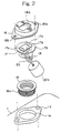
- Figure 2 is an exploded perspective drawing of the fuel gauge of Figure 1.
- 1 is a molded resin fuel tank which is mounted on top of an engine.
- a fuel supply inlet with a cap 2 and a fuel filter 3 and a fuel gauge unit 14.
- the fuel gauge unit 14 comprises a cover plate 16, which is a molded plate; a gauge body 17, which is formed from a transparent synthetic resin and which has a window 17a; an interior guide cylinder 21, which fits into the gauge body 17, and which has a long hole in its raised bottom to guide the arm of indicator 22a; a cylindrical packing 18, which seals the gauge against the fuel; a shaft 19, which extends through the gauge body 17 and the interior guide cylinder 21, and whose ends are anchored in place; and an indicator bearing 22, which is supported by the shaft 19 in such a way that it is free to rotate, and to which is fixed float 22b, which sits on the surface of the fuel in fuel tank 1.
- a protruding rectangular portion 17b On the upper surface 17d of gauge body 17 is a protruding rectangular portion 17b, which is elevated above the upper surface 17d by a fixed amount.
- the protruding rectangular portion 17b has dimensions which allow it to fit exactly into the rectangular hole 16a in the cover plate 16. The engagement of protruding rectangular portion 17b in hole 16a determines the rotational angle of the gauge body 17 and forms a rotational position.
- the indicator is easier to see. And because a scale which goes from "E” to "F” is engraved on the cover plate, no extra plate for markings on it is needed. This also contributes to lowering the cost of the gauge.
Landscapes
- Physics & Mathematics (AREA)
- Fluid Mechanics (AREA)
- General Physics & Mathematics (AREA)
- Level Indicators Using A Float (AREA)
- Cooling, Air Intake And Gas Exhaust, And Fuel Tank Arrangements In Propulsion Units (AREA)
Claims (4)
- Kraftstoff-Meßeinheit (14) zur visuellen Anzeige einer Kraftstoffmenge in einem Kraftstofftank (1), aufweisend:dadurch gekennzeichnet, daßeinen Meßkörper (17) mit einem durchsichtigen Fenster (17a),einen drehbar vom Meßkörper (17) getragenen und durch das Fenster (17a) sichtbaren Zeiger (22a),einen mit dem Zeiger (22a) verbundenen Schwimmer (22b) zum Schwimmen auf dem Kraftstoff im Kraftstofftank (1), undeine Abdeckplatte (16) zur Befestigung am Kraftstofftank (1), die den Meßkörper (17) abdeckt und eine das Fenster (17a) freigebende Öffnung (16a) aufweist,
das durchsichtige Fenster (17a) von einem nach oben vorstehenden oberen Abschnitt (17b) des Meßkörpers (17) gebildet ist, der in die Öffnung (16a) so eingreift, daß der Kraftstoff-Meßkörper (17) an einer Drehung relativ zur Abdeckplatte (16) gehindert wird. - Einheit nach Anspruch 1 mit einer zylindrischen Dichtung (18) zum Dichten des Meßkörpers (17) in einem Befestigungsloch (1a) des Kraftstofftanks (1) gegenüber dem Kraftstoff.
- Einheit nach Anspruch 1 oder 2 mit einem inneren Führungszylinder (21), der in den Meßkörper (17) paßt und ein längliches Loch zur Führung des Zeigers (22a) aufweist.
- Einheit nach einem der Ansprüche 1 bis 3, wobei die Abdeckplatte (16) mit einer Kraftstoffskala und das durchsichtige Fenster (17a) mit einer der Kraftstoffskala entsprechenden Pegellinie (17c) versehen ist.
Applications Claiming Priority (2)
| Application Number | Priority Date | Filing Date | Title |
|---|---|---|---|
| JP02916398A JP3969820B2 (ja) | 1998-01-27 | 1998-01-27 | 燃料タンクの燃料ゲージ装置 |
| JP2916398 | 1998-01-27 |
Publications (2)
| Publication Number | Publication Date |
|---|---|
| EP0932031A1 EP0932031A1 (de) | 1999-07-28 |
| EP0932031B1 true EP0932031B1 (de) | 2001-09-26 |
Family
ID=12268590
Family Applications (1)
| Application Number | Title | Priority Date | Filing Date |
|---|---|---|---|
| EP98124840A Expired - Lifetime EP0932031B1 (de) | 1998-01-27 | 1998-12-29 | Kraftstoffmesser für einen Kraftsofftank |
Country Status (6)
| Country | Link |
|---|---|
| US (1) | US6341524B1 (de) |
| EP (1) | EP0932031B1 (de) |
| JP (1) | JP3969820B2 (de) |
| CN (1) | CN1174226C (de) |
| DE (1) | DE69801804T2 (de) |
| TW (1) | TW438689B (de) |
Cited By (1)
| Publication number | Priority date | Publication date | Assignee | Title |
|---|---|---|---|---|
| AU2012203010B2 (en) * | 2011-11-11 | 2014-07-31 | Hansen Developments Limited | Liquid Level Indicator Mounting Device |
Families Citing this family (11)
| Publication number | Priority date | Publication date | Assignee | Title |
|---|---|---|---|---|
| US6415618B1 (en) * | 2000-08-30 | 2002-07-09 | Lg Electronics Inc. | Device for detecting full dehumidifier water tank |
| JP2005222710A (ja) * | 2004-02-03 | 2005-08-18 | Fujitsu Component Ltd | 液体燃料電池装置 |
| DE102004043717B4 (de) | 2004-09-09 | 2007-11-29 | Siemens Ag | Vorrichtung zur Erfassung eines Füllstandes |
| JP4657167B2 (ja) * | 2006-08-01 | 2011-03-23 | 本田技研工業株式会社 | 燃料ゲージ |
| KR100939016B1 (ko) | 2007-10-01 | 2010-01-27 | 주식회사 캐놀 | 압력용기용 플로트 게이지 모듈 |
| US20100089306A1 (en) * | 2008-09-04 | 2010-04-15 | Stant Manufacturing Inc. | Portable fuel gauge for fuel tank |
| US20130146494A1 (en) * | 2011-12-12 | 2013-06-13 | Briggs & Stratton Corporation | Fuel filling system |
| CN104417890B (zh) * | 2013-08-20 | 2018-05-18 | 珠海格力电器股份有限公司 | 水箱及包括该水箱的除湿机 |
| JP6497517B2 (ja) * | 2015-07-13 | 2019-04-10 | 株式会社日本ロック | 液面検出装置 |
| CN105784072B (zh) * | 2016-03-28 | 2018-10-19 | 海信(广东)空调有限公司 | 一种除湿机用水满报警装置 |
| CN109751940B (zh) * | 2019-01-30 | 2024-04-19 | 南京栖霞科技产业发展有限公司 | 一种加油口盖的锁扣舌检测装置 |
Family Cites Families (10)
| Publication number | Priority date | Publication date | Assignee | Title |
|---|---|---|---|---|
| US943868A (en) * | 1909-07-19 | 1909-12-21 | Arthur S Garlick | Liquid-gage. |
| US1020785A (en) * | 1911-05-05 | 1912-03-19 | Perry E Tanner | Tank-gage. |
| US1202854A (en) * | 1914-11-05 | 1916-10-31 | William C Knight | Fluid-gage. |
| CH286162A (de) * | 1950-11-25 | 1952-10-15 | Noethiger Wullschleger & Cie A | Vorrichtung an Flüssigkeitsbehälter zum Anzeigen des Flüssigkeitsniveaus. |
| US4441364A (en) * | 1981-05-22 | 1984-04-10 | Thomas G. Faria Corp. | Liquid-level transducer/indicator |
| US4574631A (en) * | 1985-08-12 | 1986-03-11 | Johnson Jr Stanley A | Liquid level molded indicating gage portions |
| JPS6251030A (ja) | 1985-08-30 | 1987-03-05 | Hitachi Ltd | 磁気デイスクの製造方法 |
| JPH0697177B2 (ja) * | 1986-06-13 | 1994-11-30 | 株式会社トヨトミ | カ−トリツジ油タンクの油量計 |
| US5025764A (en) * | 1990-04-12 | 1991-06-25 | Mitsubishi Jukogyo Kabushiki Kaisha | Lubricant oil amount detector of a vertical shaft type engine |
| JP3333805B2 (ja) * | 1996-02-16 | 2002-10-15 | 株式会社クボタ | レベルゲージ付きタンク |
-
1998
- 1998-01-27 JP JP02916398A patent/JP3969820B2/ja not_active Expired - Lifetime
- 1998-12-29 EP EP98124840A patent/EP0932031B1/de not_active Expired - Lifetime
- 1998-12-29 DE DE69801804T patent/DE69801804T2/de not_active Expired - Fee Related
-
1999
- 1999-01-20 CN CNB991012313A patent/CN1174226C/zh not_active Expired - Fee Related
- 1999-01-22 TW TW088100994A patent/TW438689B/zh not_active IP Right Cessation
- 1999-01-27 US US09/238,063 patent/US6341524B1/en not_active Expired - Fee Related
Cited By (1)
| Publication number | Priority date | Publication date | Assignee | Title |
|---|---|---|---|---|
| AU2012203010B2 (en) * | 2011-11-11 | 2014-07-31 | Hansen Developments Limited | Liquid Level Indicator Mounting Device |
Also Published As
| Publication number | Publication date |
|---|---|
| JP3969820B2 (ja) | 2007-09-05 |
| TW438689B (en) | 2001-06-07 |
| EP0932031A1 (de) | 1999-07-28 |
| CN1229912A (zh) | 1999-09-29 |
| JPH11208295A (ja) | 1999-08-03 |
| CN1174226C (zh) | 2004-11-03 |
| DE69801804D1 (de) | 2001-10-31 |
| DE69801804T2 (de) | 2002-05-29 |
| US6341524B1 (en) | 2002-01-29 |
Similar Documents
| Publication | Publication Date | Title |
|---|---|---|
| AU782859B2 (en) | Liquid level gauge with removable hall device | |
| EP0932031A1 (de) | Kraftstoffmesser für einen Kraftsofftank | |
| CA1158454A (en) | Differential pressure gauge | |
| US2473581A (en) | Indicating instrument with magnetic | |
| CN1536586B (zh) | 刻度盘显示式测量器及转动不足一周的刻度盘量具 | |
| US20100089306A1 (en) | Portable fuel gauge for fuel tank | |
| US4574631A (en) | Liquid level molded indicating gage portions | |
| US2255310A (en) | Oil gauge | |
| US3659457A (en) | Register box and lid for meters | |
| JPS62294916A (ja) | カ−トリツジ油タンクの油量計 | |
| US20110041600A1 (en) | Wiper assembly for fuel level indication | |
| JP4657167B2 (ja) | 燃料ゲージ | |
| EP0292060A1 (de) | Füllstandsanzeiger mit stirnseitiger Ablesung | |
| JPH0234587Y2 (de) | ||
| AU2004222795B2 (en) | Liquid level gauge with removable hall device | |
| KR100679489B1 (ko) | 제수밸브용 인디케이터 | |
| JPH0523957Y2 (de) | ||
| JPH0533937Y2 (de) | ||
| JP3038222U (ja) | 燃料油タンクのゲージ取付構造 | |
| JP4345998B2 (ja) | 乾式水道メータ | |
| JP3110267U (ja) | 燃料油タンクのゲージの取付示標 | |
| US1648731A (en) | Liquid gauge | |
| JPH0127845Y2 (de) | ||
| JPS606739Y2 (ja) | 車輛用マスタシリンダの油槽 | |
| JPS5817222Y2 (ja) | 液量表示装置 |
Legal Events
| Date | Code | Title | Description |
|---|---|---|---|
| PUAI | Public reference made under article 153(3) epc to a published international application that has entered the european phase |
Free format text: ORIGINAL CODE: 0009012 |
|
| AK | Designated contracting states |
Kind code of ref document: A1 Designated state(s): DE FR GB IT |
|
| AX | Request for extension of the european patent |
Free format text: AL;LT;LV;MK;RO;SI |
|
| 17P | Request for examination filed |
Effective date: 20000112 |
|
| AKX | Designation fees paid |
Free format text: DE FR GB IT |
|
| 17Q | First examination report despatched |
Effective date: 20000727 |
|
| GRAG | Despatch of communication of intention to grant |
Free format text: ORIGINAL CODE: EPIDOS AGRA |
|
| GRAG | Despatch of communication of intention to grant |
Free format text: ORIGINAL CODE: EPIDOS AGRA |
|
| GRAH | Despatch of communication of intention to grant a patent |
Free format text: ORIGINAL CODE: EPIDOS IGRA |
|
| GRAH | Despatch of communication of intention to grant a patent |
Free format text: ORIGINAL CODE: EPIDOS IGRA |
|
| GRAA | (expected) grant |
Free format text: ORIGINAL CODE: 0009210 |
|
| AK | Designated contracting states |
Kind code of ref document: B1 Designated state(s): DE FR GB IT |
|
| REF | Corresponds to: |
Ref document number: 69801804 Country of ref document: DE Date of ref document: 20011031 |
|
| REG | Reference to a national code |
Ref country code: GB Ref legal event code: IF02 |
|
| ET | Fr: translation filed | ||
| PLBE | No opposition filed within time limit |
Free format text: ORIGINAL CODE: 0009261 |
|
| STAA | Information on the status of an ep patent application or granted ep patent |
Free format text: STATUS: NO OPPOSITION FILED WITHIN TIME LIMIT |
|
| 26N | No opposition filed | ||
| PGFP | Annual fee paid to national office [announced via postgrant information from national office to epo] |
Ref country code: FR Payment date: 20061208 Year of fee payment: 9 |
|
| PGFP | Annual fee paid to national office [announced via postgrant information from national office to epo] |
Ref country code: DE Payment date: 20061221 Year of fee payment: 9 |
|
| PGFP | Annual fee paid to national office [announced via postgrant information from national office to epo] |
Ref country code: GB Payment date: 20061227 Year of fee payment: 9 |
|
| PGFP | Annual fee paid to national office [announced via postgrant information from national office to epo] |
Ref country code: IT Payment date: 20061231 Year of fee payment: 9 |
|
| GBPC | Gb: european patent ceased through non-payment of renewal fee |
Effective date: 20071229 |
|
| PG25 | Lapsed in a contracting state [announced via postgrant information from national office to epo] |
Ref country code: DE Free format text: LAPSE BECAUSE OF NON-PAYMENT OF DUE FEES Effective date: 20080701 |
|
| REG | Reference to a national code |
Ref country code: FR Ref legal event code: ST Effective date: 20081020 |
|
| PG25 | Lapsed in a contracting state [announced via postgrant information from national office to epo] |
Ref country code: GB Free format text: LAPSE BECAUSE OF NON-PAYMENT OF DUE FEES Effective date: 20071229 |
|
| PG25 | Lapsed in a contracting state [announced via postgrant information from national office to epo] |
Ref country code: FR Free format text: LAPSE BECAUSE OF NON-PAYMENT OF DUE FEES Effective date: 20071231 |
|
| PG25 | Lapsed in a contracting state [announced via postgrant information from national office to epo] |
Ref country code: IT Free format text: LAPSE BECAUSE OF NON-PAYMENT OF DUE FEES Effective date: 20071229 |