EP0932095A2 - Struktur eines Schalthebels für eine Fahrspielmaschine - Google Patents
Struktur eines Schalthebels für eine Fahrspielmaschine Download PDFInfo
- Publication number
- EP0932095A2 EP0932095A2 EP99101046A EP99101046A EP0932095A2 EP 0932095 A2 EP0932095 A2 EP 0932095A2 EP 99101046 A EP99101046 A EP 99101046A EP 99101046 A EP99101046 A EP 99101046A EP 0932095 A2 EP0932095 A2 EP 0932095A2
- Authority
- EP
- European Patent Office
- Prior art keywords
- shift lever
- car
- player
- game machine
- driving game
- Prior art date
- Legal status (The legal status is an assumption and is not a legal conclusion. Google has not performed a legal analysis and makes no representation as to the accuracy of the status listed.)
- Granted
Links
- 230000004044 response Effects 0.000 claims abstract description 12
- 238000000034 method Methods 0.000 description 8
- 230000008569 process Effects 0.000 description 8
- 230000008859 change Effects 0.000 description 5
- 238000010586 diagram Methods 0.000 description 3
- 230000006870 function Effects 0.000 description 3
- 230000006399 behavior Effects 0.000 description 2
- 230000000881 depressing effect Effects 0.000 description 2
- 230000009471 action Effects 0.000 description 1
- 230000006835 compression Effects 0.000 description 1
- 238000007906 compression Methods 0.000 description 1
- 230000003247 decreasing effect Effects 0.000 description 1
- 230000001934 delay Effects 0.000 description 1
- 230000004048 modification Effects 0.000 description 1
- 238000012986 modification Methods 0.000 description 1
- 230000009467 reduction Effects 0.000 description 1
- 238000009877 rendering Methods 0.000 description 1
- 230000000284 resting effect Effects 0.000 description 1
- 230000000717 retained effect Effects 0.000 description 1
- 238000004088 simulation Methods 0.000 description 1
- XLYOFNOQVPJJNP-UHFFFAOYSA-N water Substances O XLYOFNOQVPJJNP-UHFFFAOYSA-N 0.000 description 1
Images


Classifications
-
- G—PHYSICS
- G05—CONTROLLING; REGULATING
- G05G—CONTROL DEVICES OR SYSTEMS INSOFAR AS CHARACTERISED BY MECHANICAL FEATURES ONLY
- G05G7/00—Manually-actuated control mechanisms provided with one single controlling member co-operating with one single controlled member; Details thereof
- G05G7/02—Manually-actuated control mechanisms provided with one single controlling member co-operating with one single controlled member; Details thereof characterised by special provisions for conveying or converting motion, or for acting at a distance
-
- A—HUMAN NECESSITIES
- A63—SPORTS; GAMES; AMUSEMENTS
- A63F—CARD, BOARD, OR ROULETTE GAMES; INDOOR GAMES USING SMALL MOVING PLAYING BODIES; VIDEO GAMES; GAMES NOT OTHERWISE PROVIDED FOR
- A63F2300/00—Features of games using an electronically generated display having two or more dimensions, e.g. on a television screen, showing representations related to the game
- A63F2300/10—Features of games using an electronically generated display having two or more dimensions, e.g. on a television screen, showing representations related to the game characterized by input arrangements for converting player-generated signals into game device control signals
- A63F2300/1062—Features of games using an electronically generated display having two or more dimensions, e.g. on a television screen, showing representations related to the game characterized by input arrangements for converting player-generated signals into game device control signals being specially adapted to a type of game, e.g. steering wheel
-
- A—HUMAN NECESSITIES
- A63—SPORTS; GAMES; AMUSEMENTS
- A63F—CARD, BOARD, OR ROULETTE GAMES; INDOOR GAMES USING SMALL MOVING PLAYING BODIES; VIDEO GAMES; GAMES NOT OTHERWISE PROVIDED FOR
- A63F2300/00—Features of games using an electronically generated display having two or more dimensions, e.g. on a television screen, showing representations related to the game
- A63F2300/80—Features of games using an electronically generated display having two or more dimensions, e.g. on a television screen, showing representations related to the game specially adapted for executing a specific type of game
- A63F2300/8017—Driving on land or water; Flying
Definitions
- the present invention relates to a shift lever structure suited for use in a driving game machine in which movement of a moving object is simulated in a moving space displayed on an image monitor by a simulated driving operation of a player.
- a driving game machine in which a player performs a simulated driving operation while viewing an image of a running space displayed on an image monitor so that a car (the player's car) runs within the running space according to the simulated driving operation and competes with another car (the opponent car) in the simulated running.
- This driving game machine is provided with a simulated driver's seat that simulates a driver's seat of an actual car.
- An accelerator pedal and a brake pedal are disposed at the feet of the player sitting on the simulated driver's seat, and a shift lever is disposed on the side of the player so as to switch between advancing and reversing of the car.
- the image monitor is placed to face the front of the player.
- a running space of the car including roads, buildings, etc. is displayed as a three-dimensional image. Shown in the field of view of the player are the player's car that the player is driving, and an opponent car driven by a computer or a player at another driving game machine. The player competes with the opponent car in a predetermined game while operating operation means, such as a steering wheel, pedals, and a shift lever.
- a racing game in which a competition for precedence is made in driving on a road with a number of branches in a virtual city.
- high-speed running is performed by shifting the shift lever.
- the shift lever is allowed to be shifted to a reverse position.
- the shift lever can be switched between an advancing position for advancing the car, and a reverse position for reversing the car.
- the player's car In a game played with such a driving game machine, the player's car is mainly advanced and is sometimes reversed according to the circumstances. Moreover, from the viewpoint of the characteristics of the game, it is preferable to advance the player's car immediately after being reversed. In switching the conventional shift lever from reverse to advance, however, the player must grip the shift lever again, and shift the shift lever from the reverse position to the advance position. The shift change operation takes much time, which delays the timing of advance, and diminishes the interest.
- the present invention has been made to solve the above problems. It is accordingly an object of the present invention to provide a shift lever structure of a driving game machine in which prompt switching is possible from a reversing state to an advancing state, thereby making a driving game more interesting.
- a shift lever structure of a driving game machine in which a moving object displayed on an image monitor advances or reverses in a simulated running space in response to a control signal from a control section according to a simulated driving operation of a player
- the shift lever structure including: a shift lever capable of changing its position between an advance position for advancing the moving object and a reverse position for reversing the moving object; a position detecting means for detecting the shift lever being placed in the positions; and a first urging means for urging the shift lever toward the advance position.
- the shift lever since the shift lever is usually placed in the advance position because of the urging force of the first urging means, the player can enjoy a driving game while advancing the moving object with his or her attention focused on the operation of a steering wheel, an accelerator pedal, and the like, without paying attention to the shift lever during the driving game. Only when reversing the moving object, the player grips the shift lever and applies force to the shift lever from the advance position toward the reverse position, whereby the position of the shift lever is changed to the reverse position against the urging force of the first urging means, and the moving object is allowed to reverse. It is not very difficult to perform a reversing operation while gripping the shift lever in one hand and steering by the other hand, and the reversing operation is not performed for a long time, which does not produce a difficult feeling in operation.
- a second urging means is provided to give a tactile response to an operation for changing the drive position of the shift lever.
- the player reliably realizes, from the tactile response given by the second urging means, that the shift lever has been shifted from the advance position to the reverse position. This eliminates the need for troublesome operations, for example, visually checking the position of the shift lever, and allows the player to be absorbed in the game.
- the position detecting means is a limit switch.
- the position change between the advance position and the reverse position can be reliably detected, although the limit switch is a simple and inexpensive component. It is thereby possible to reduce component cost and to detect the position more reliably. While the limit switch may be disposed at both the advance and reverse positions, even when it is disposed at one of the positions, both the positions can be detected.
- the first urging means is a coil spring.
- the coil spring elastically deforms in the longitudinal direction by a greater length than other springs, such as a leaf spring and a V-spring, and thereby applies stable urging force to the shift lever.
- control section informs the moving object of the traveling speed corresponding to the degree of depression of the accelerator, and exerts control so that the maximum speed when the shift lever is placed in the reverse position is lower than when the shift lever is placed in the advance position.
- a second image monitor is provided to display a simulated moving space behind the moving object at least when the shift lever is placed in the reverse position.
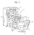
- FIG. 1 is a perspective view of the driving game machine.
- a driving game machine 1 has a basic configuration comprising a simulated driver's seat 2, disposed on the rear part of a base B placed on a floor F, that simulates a driver's seat of a car; a panel board section 3 disposed on the front part of the base B; and an image monitor device 4 placed on the floor F further ahead of the panel board section 3.
- the simulated driver's seat 2 and the panel board section 3 are placed on the base B so as to face each other in the longitudinal direction. Accordingly, a player sitting on the simulated driver's seat 2 faces the panel board section 3 and the image monitor device 4.
- the rear part of the simulated driver's seat 2 is surrounded by a rear fence member 21 that is U-shaped in plan view, and the left side thereof is guarded by a side fence member 22. Thereby, a driving space separated from the outside space is formed at the simulated driver's seat 2, and the player sitting on the simulated driver's seat 2 can have a realistic feeling similar to that of riding in an actual car.
- the side fence member 22 is composed of a box member 23 that is hollow inside and is elongated in the longitudinal direction, and a top plate 24 for covering a top opening of the box member 23.
- the height of the box member 23 is set such that the player sitting on the simulated driver's seat 2 can rest his or her elbow thereon.
- a slot 24a is cut extending in the longitudinal direction so as to allow a shift lever 51 of the present invention, which will be described later, to protrude therethrough to the outside.
- the position at which the slot 24a is cut is set so that the player can grip the shift lever 51 with his or her elbow resting on the top plate 24.
- the panel board section 3 comprises a pair of widthwise side plates 31, a ceiling plate 32 laid between the upper edges of these side plates 31, and a front plate 33 disposed at the front ends of the side plates 31 and the ceiling plate 32.
- a panel board 34 is fitted in a section surrounded by the rear ends of the side plates 31 and the ceiling plate 32 so that it faces the player.
- Such a panel board 34 is provided, at its center, with a steering shaft 34a that inclines upward to the rear side.
- a steering wheel 34b that serves as a steering tool is mounted at the rear end of the steering shaft 34a, and instruments 34c, such as a speedometer, are disposed on the right and left sides of the steering wheel 34b.
- instruments 34c such as a speedometer
- a start button 34d to be operated at the beginning of a game is disposed on the upper left side of the steering wheel 34b.
- An accelerator pedal 33a and a brake pedal 33b are provided in the rear of the front plate 33 and at the feet of the player sitting on the simulated driver's seat 2.
- the side fence member 22 on the left side is provided with a shift lever structure 5 including the shift lever 51 of the present invention, which will be described later.
- the image monitor device 4 comprises a box-shaped casing 41, a control means and an image forming means disposed inside the casing 41, which are not shown, and a flat monitor screen 42 on which three-dimensional images are projected by the image forming means.
- a virtual running space (moving space) for a car including roads and buildings is shown as a three-dimensional image under the control of the control means.
- Shown in the field of view of the player are a player's car (moving object) C1 that the player is driving, and an opponent car C2 driven by a computer or a player at another driving game machine.
- the player drives his or her own car C1 by manipulating the steering wheel 34b, the accelerator pedal 33a, the brake pedal 33b, and the shift lever 51, thereby competing with the opponent car C2 in a predetermined game.
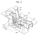
- the shift lever structure 5 comprises the shift lever 51 for switching between the advance and reversing of the player's car C1, a box-shaped casing 52 for housing the base end of the shift lever 51, the casing 52 being open at its top, a limit switch 53 disposed inside the casing 52, and a coil spring (first urging means) 54 for urging the shift lever 51 in a direction that tilts the shift lever 51 forward.
- a shift lever 51 is structured to switch the position thereof between an advance position for advancing the player's car C1, where the shift lever 51 tilts forward, and a reverse position for reversing the car C1.
- the shift lever 51 is composed of a sticklike lever body 51a, a fulcrum member 51b shaped like a rectangular parallelepiped and formed at a position somewhat lower than the vertical center of the lever body 5la, and a ball-shaped grip 51c disposed at the top of the lever body 51a.
- An annular groove 51d is formed in an annular and concave manner at the bottom of the lever body 51a, and retains one end of the first coil spring 54.
- the fulcrum member 51b has a through hole 51e bored to extend in the widthwise direction, and a support shaft 55, which supports the shift lever 51 and serves as a pivot center, is passed through the through hole 51e in sliding contact therewith.
- the casing 52 has a pair of longitudinal wings 52a that extend from the front and rear upper ends thereof in a direction in which they separate from each other.
- the wings 52a are fixed to the frame 25 by screwing or the like, whereby the casing 52 is embedded in the top center of the side fence member 22.
- Mounting holes are bored in proximity to the centers of a pair of widthwise side plates of the casing 52 so that the support shaft 55 is passed therethrough.
- the support shaft 55 is passed through the mounting holes of the casing 52 and the through hole 51e of the fulcrum member 51b, and both ends thereof are subjected to caulking or the like, which allows the shift lever 51 to pivot about the support shaft 55.
- the length of the slot 24a cut in the top plate 24 is set corresponding to the pivot range of the shift lever 51, so that the front and rear edges of the slot 24a function as stoppers when the shift lever 51 pivots within the range.
- a retaining hole 52b is bored in the rear wall of the casing 52.
- the first coil spring 54 is retained by the retaining hole 52b at the rear end, and by the annular groove 51d of the shift lever 51 at the front end, whereby the lever body 51a is urged in a direction to tilt the grip 51c forward, and the shift lever 51 is usually in a forward tilting position, as shown in FIGS. 2 and 3A.
- the limit switch 53 is of a normally-open type (that outputs an open signal in the open state), which is composed of a switch body 53a fixed at an appropriate position of the front wall of the casing 52 and having a fixed contact piece inside thereof, and a long movable arm 53b extending from an appropriate lower position of the switch body 53a toward the rear top, mounted at its lower end pivotally about the fulcrum, and urged by an urging means (not shown) from the switch body 53a in a standing (backward tilting) direction.
- a normally-open type that outputs an open signal in the open state
- the limit switch 53 outputs a close signal indicating a closed state when the movable arm 53b is pressed toward the switch body 53a into contact with the fixed contact piece. Moreover, the limit switch 53 is positioned so as to interfere with the lower end of the shift lever 51 when the shift lever 51 pivots.
- the movable arm 53b When the shift lever 51 is in the forward tilting position, the movable arm 53b is in an open position, as shown in FIG. 3A, and therefore, an open signal is output.
- the shift lever 51 is brought into the backward tilting position against the urging force of the first coil spring 54, as shown in FIG. 3B, the movable arm 53b is abutted against the lower end of the shift lever 51 and is pressed toward the switch body 53a, and therefore, a closed signal is output.
- FIGS. 4A and 4B are cross-sectional views of a shift lever structure 5a according to another embodiment of the present invention, as viewed from the side, respectively showing a state in which the shift lever 51 is placed in the advance position, and a state in which the shift lever 51 is placed in the reverse position.
- a second coil spring (second urging means) 56 formed of what is called a compression spring, which is used to exert urging force in the expanding direction, is interposed between the lower end of the lever body 51a and the inner bottom face of the casing 52.
- the urging force of the second coil spring 56 is set to be smaller than that of the first coil spring 54 that urges the shift lever 51 toward the advance position.
- the lower end of the second coil spring 56 is positioned directly below the axial center of the support shaft 55.
- Other structures are similar to those in the above embodiment.
- the shift lever 51 in the state shown in FIG. 4A, the shift lever 51 is positioned in the advance position by the urging force of the second coil spring 56 in addition to the urging force of the first coil spring 54.
- the urging force of the second coil spring 56 acts in the direction that tilts the shift lever 51 forward until the shift lever 51 stands upright.
- the shift lever 51 is pulled further back beyond the upright position, since the urging force of the second coil spring 56 acts in the direction that tilts the shift lever 51 backward, as shown in FIG. 4B, the operation of the shift lever 51 is rapidly eased. At this time, the player receives a tactile response, and can know that the shift lever 51 is placed in the reverse position.
- the shift lever 51 pivots counterclockwise about the support shaft 55 by the action of the first coil spring 54 having a larger urging force than that of the second coil spring 56, and returns to the advance position.
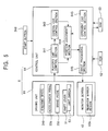
- FIG. 5 is a block diagram showing a control system for the driving game.
- a control system 6 is incorporated in the image monitor device 4, and comprises a driving unit 61 including the steering wheel 34b, the accelerator pedal 33a, the brake pedal 33b, and the shift lever 51, a ROM 62 that serves as a read-only memory medium for storing a basic program and the like, a RAM 63 that is a random-access memory medium for temporarily storing data that is being processed, as necessary, a control unit 64 for controlling the driving of the player's car Cl and the opponent car C2 according to a game program in response to an input signal from the driving unit 61, the monitor screen 42, and the start button 34d.
- a driving unit 61 including the steering wheel 34b, the accelerator pedal 33a, the brake pedal 33b, and the shift lever 51
- a ROM 62 that serves as a read-only memory medium for storing a basic program and the like
- a RAM 63 that is a random-access memory medium for temporarily storing
- the ROM 62 stores behavior programs of the player's car Cl and the opponent car C2, coordinate data on roads, obstacles, and the like, in the running space of the game, etc. These data are read into the control unit 64 in response to an operation signal from the driving unit 61 produced by operating the steering wheel 34b or the like, and are subjected to a simulation process in accordance with automotive engineering, whereby images on the monitor screen 42 are sequentially renewed.
- a rearview mirror region 42a is provided as a second image monitor.
- This rearview mirror region 42a corresponds to a rearview mirror that is virtually provided in the player's car Cl, and displays images in the rear of the player's car C1 that can be regarded as being optically reflected in the virtual rearview mirror from the point of view of a virtual driver of the car C1.
- the player can check the running space behind the car C1 by viewing images in the rearview mirror region 42a. By doing this, the player can reverse the car while checking the rear view, which ensures a good reversing operation.
- the control unit 64 comprises a player's car control section 641, a general car control section 642, an opponent car control section 643, a position judgement section 644, and an image processing section 645.
- the player's car control section 641 controls the running of the player's car C1 by using operation signals sent from the driving unit 61, that is, operation signals from the steering wheel 34b, the accelerator pedal 33a, the brake pedal 33b, and the shift lever 51, which serve as operation means, and the car behavior program based on automotive engineering that is stored in the ROM 62.
- Images in front of the player's car Cl projected on the monitor screen 42 and images behind the player's car C1 projected on the rearview mirror region 42a change moment by moment, centered on the player's car C1, in response to the operations of the operation means.
- the player's car control section 641 includes a judging means for judging the state of a signal from the limit switch 53.
- the judging means directs the player's car C1 to advance, in response to this open signal, and calculates and sets the running speed for advancing in accordance with the degree of depression of the accelerator pedal 33a.
- the judging means directs the player's car C1 to reverse, in response to this close signal, and calculates and sets the running speed for reversing in accordance with the degree of depression of the accelerator pedal 33a. This allows the player's car Cl to reliably move in the forward and backward directions within the running space, corresponding to the set position of the shift lever 51.
- the player's car control section 641 is also programmed so as to inform the player's car C1 of the traveling speed corresponding to the degree of depression of the accelerator pedal 33a. Therefore, when the player strongly depresses the accelerator pedal 33a, the player's car C1 on the monitor screen 42 runs at a corresponding high speed. When the degree of depression is small, the speed of the player's car C1 is decreased correspondingly. In this embodiment, the rate of change of speed to the degree of depression varies depending on the set position of the shift lever 51.
- the player's car control section 641 is programmed so as to output a command signal for commanding that the traveling speed of the player's car C1 when the shift lever 51 is placed in the reverse position is lower than when the shift lever 51 is placed in the advance position.
- the degree of depression of the accelerator pedal 33a for reversing the player's car C1 is the same as for advancing, the reversing speed of the player's car C1 is lower than the advancing speed. Therefore, it is possible to reliably perform a reversing operation, which is more difficult than advancing.
- the traveling speed may be fixed, regardless of the degree of depression of the accelerator pedal 33a.
- the general car control section 642 controls the running of one or a predetermined number of general cars, other than the player's car C1 and the opponent car C2, within the running space on the monitor screen 42. These general cars function as obstacles in the driving game.
- the opponent car control section 643 controls the running of the opponent car C2 that competes with the player's car C1, and subjects the opponent car C2 to a predetermined running process in connection with the player's car control section 641.
- the position judgement section 644 searches for all cars existing within a preset field of view, based on coordinate data on the player's car C1, the opponent car C2, and general cars that are sent from the player's car control section 641, the general car control section 642, and the opponent car control section 643, and outputs data on the search result to the image processing section 645.
- the position judgment section 644 also judges the positional relationship between the player's car C1, and the opponent car C2 and general cars, such as a collision including a minor collision, the positional relationship between the player's car C1 and a fixed obstacle, and the like.
- the position judgement section 644 sends a collision signal to the image processing section 645. Furthermore, the position judgment section 644 has the functions of determining a "tagger” car carrying the time bomb Q, and of exchanging the "tagger” between the player's car C1 and the opponent car C2 when the cars touch.
- the image processing section 645 subjects all the cars searched by the position judgement section 644 and specific views (roads, buildings, etc.) in the running space within the field of view, to a well-known three-dimensional image process such as a geometric process or a rendering process. A three-dimensional image produced as the result of the process is displayed on the monitor screen 42.
- the image processing section 645 also counts the time that elapsed from the beginning of the game, and displays on the monitor screen 42 an image of the exploding time bomb Q, when a preset time has elapsed.
- a predetermined initial image first appears on the monitor screen 42.
- an operation signal is input to the player's car control section 641, and a predetermined process is executed.
- a process signal is input to the position judgment section 644, and time-varying views in the running space centered on the player's car C1 are shown on the monitor screen 42.
- the opponent car C2 also runs under the control of the opponent car control section 643, and the driving game proceeds in which the player's car C1 and the opponent car C2 chase each other.
- the time bomb Q carried by one of the player's car C1 and the opponent car C2 is transferred to the other car by a contact therebetween and the preset time elapses, the time bomb Q explodes, thereby finishing the game.
- FIGS. 3A and 3B are cross-sectional views of the shift lever structure 5 shown in FIG. 2, as viewed from the side, respectively showing a state in which the shift lever 51 is placed in the advance position, and a state in which the shift lever 51 is placed in the reverse position.
- the shift lever 51 is usually placed in the advance position because of the urging force of the first coil spring 54. Therefore, when the player depresses the accelerator pedal 33a to move the player's car C1, the car C1 advances.
- the shift lever 51 is usually placed in the advance position by the urging force of the first coil spring 54, and the player's car C1 can be reversed only when the shift lever 51 is moved to the reverse position against the urging force of the first coil spring 54 and is held in this position. Even if the shift lever 51 is moved to the reverse position, it is automatically returned to the advance position only by removing the hand from the grip 51c. Therefore, even when the player's car C1 is tactically reversed during the driving game, it is possible to greatly shorten the operation time until the player's car C1 advances, compared with the conventional art in which the shift lever is forcibly switched to the advance position while gripping the grip 51c. Even when the car temporarily reverses, the driving game, which mainly deals with advancing, can be made more interesting.
Landscapes
- Physics & Mathematics (AREA)
- General Physics & Mathematics (AREA)
- Engineering & Computer Science (AREA)
- Automation & Control Theory (AREA)
- Mechanical Control Devices (AREA)
Applications Claiming Priority (2)
| Application Number | Priority Date | Filing Date | Title |
|---|---|---|---|
| JP01111098A JP3167973B2 (ja) | 1998-01-23 | 1998-01-23 | ドライビングゲーム機のシフトレバー構造 |
| JP1111098 | 1998-01-23 |
Publications (3)
| Publication Number | Publication Date |
|---|---|
| EP0932095A2 true EP0932095A2 (de) | 1999-07-28 |
| EP0932095A3 EP0932095A3 (de) | 1999-12-01 |
| EP0932095B1 EP0932095B1 (de) | 2006-03-29 |
Family
ID=11768881
Family Applications (1)
| Application Number | Title | Priority Date | Filing Date |
|---|---|---|---|
| EP99101046A Expired - Lifetime EP0932095B1 (de) | 1998-01-23 | 1999-01-22 | Struktur eines Schalthebels für eine Fahrspielmaschine |
Country Status (3)
| Country | Link |
|---|---|
| EP (1) | EP0932095B1 (de) |
| JP (1) | JP3167973B2 (de) |
| DE (1) | DE69930563T2 (de) |
Cited By (1)
| Publication number | Priority date | Publication date | Assignee | Title |
|---|---|---|---|---|
| CN115223417A (zh) * | 2021-04-19 | 2022-10-21 | 速模实业(深圳)有限公司 | 一种交互式模拟赛车序列档 |
Families Citing this family (2)
| Publication number | Priority date | Publication date | Assignee | Title |
|---|---|---|---|---|
| JP6281169B1 (ja) * | 2017-02-28 | 2018-02-21 | 株式会社サンセイアールアンドディ | 遊技機 |
| JP6462767B2 (ja) * | 2017-05-19 | 2019-01-30 | 株式会社タイトー | ゲーム機 |
Family Cites Families (2)
| Publication number | Priority date | Publication date | Assignee | Title |
|---|---|---|---|---|
| US5140313A (en) * | 1991-01-17 | 1992-08-18 | O Che Wen | Joy stick assembly |
| JP2740145B2 (ja) * | 1995-09-12 | 1998-04-15 | コナミ株式会社 | 多方向操作スイッチ及びこれを用いたドライビングゲーム機 |
-
1998
- 1998-01-23 JP JP01111098A patent/JP3167973B2/ja not_active Expired - Lifetime
-
1999
- 1999-01-22 DE DE69930563T patent/DE69930563T2/de not_active Expired - Lifetime
- 1999-01-22 EP EP99101046A patent/EP0932095B1/de not_active Expired - Lifetime
Non-Patent Citations (1)
| Title |
|---|
| None |
Cited By (1)
| Publication number | Priority date | Publication date | Assignee | Title |
|---|---|---|---|---|
| CN115223417A (zh) * | 2021-04-19 | 2022-10-21 | 速模实业(深圳)有限公司 | 一种交互式模拟赛车序列档 |
Also Published As
| Publication number | Publication date |
|---|---|
| EP0932095B1 (de) | 2006-03-29 |
| JPH11207030A (ja) | 1999-08-03 |
| JP3167973B2 (ja) | 2001-05-21 |
| DE69930563T2 (de) | 2007-04-05 |
| DE69930563D1 (de) | 2006-05-18 |
| EP0932095A3 (de) | 1999-12-01 |
| HK1019645A1 (en) | 2000-02-18 |
Similar Documents
| Publication | Publication Date | Title |
|---|---|---|
| JP2740145B2 (ja) | 多方向操作スイッチ及びこれを用いたドライビングゲーム機 | |
| JP2667656B2 (ja) | ドライビングゲーム機 | |
| JP3001038B2 (ja) | シミュレータ | |
| JP2935659B2 (ja) | 競争ゲーム装置 | |
| US6409597B1 (en) | Video game machine, screen display method for video game, and recording medium containing screen display program | |
| KR100648539B1 (ko) | 게임 장치 | |
| JP2828956B2 (ja) | シミュレーション装置のシート支持装置 | |
| US20070265074A1 (en) | Game program and game apparatus | |
| JP4189315B2 (ja) | ゲーム装置およびゲームプログラム | |
| US6417856B1 (en) | Image generation device and information storage medium | |
| JPH10307633A (ja) | 多方向切替操作装置 | |
| JP3384978B2 (ja) | 課題解決型乗り物ゲーム装置 | |
| EP0932095B1 (de) | Struktur eines Schalthebels für eine Fahrspielmaschine | |
| JP2005058383A (ja) | ゲーム情報処理装置及びそのコンピュータプログラム | |
| JP3523544B2 (ja) | 自動車競技ゲームのプログラムを記録した記憶媒体 | |
| JPH10261346A (ja) | 入力装置 | |
| JP4774191B2 (ja) | 操作レバー装置 | |
| HK1019645B (en) | Shift lever structure of driving game machine | |
| JPH07213740A (ja) | 操作体を用いたゲーム機械 | |
| JP2747427B2 (ja) | ゲーム装置及びその衝突判定方法 | |
| JP3403505B2 (ja) | ゲーム装置およびその移動体制御方法 | |
| JP2003340144A (ja) | ゲーム装置、ゲーム制御方法、ゲームプログラム、および記録媒体 | |
| JPH0732672U (ja) | 体感シュミレート自動車およびサーキット | |
| JPH07222864A (ja) | 体感型ビデオゲーム機 | |
| JPS62286490A (ja) | 動画表示遊戯機 |
Legal Events
| Date | Code | Title | Description |
|---|---|---|---|
| PUAI | Public reference made under article 153(3) epc to a published international application that has entered the european phase |
Free format text: ORIGINAL CODE: 0009012 |
|
| AK | Designated contracting states |
Kind code of ref document: A2 Designated state(s): DE ES FR GB IT |
|
| AX | Request for extension of the european patent |
Free format text: AL;LT;LV;MK;RO;SI |
|
| PUAL | Search report despatched |
Free format text: ORIGINAL CODE: 0009013 |
|
| AK | Designated contracting states |
Kind code of ref document: A3 Designated state(s): AT BE CH CY DE DK ES FI FR GB GR IE IT LI LU MC NL PT SE |
|
| AX | Request for extension of the european patent |
Free format text: AL;LT;LV;MK;RO;SI |
|
| RIC1 | Information provided on ipc code assigned before grant |
Free format text: 6G 05G 7/02 A, 6G 05G 9/047 B |
|
| 17P | Request for examination filed |
Effective date: 20000518 |
|
| AKX | Designation fees paid |
Free format text: DE ES FR GB IT |
|
| 17Q | First examination report despatched |
Effective date: 20031114 |
|
| GRAP | Despatch of communication of intention to grant a patent |
Free format text: ORIGINAL CODE: EPIDOSNIGR1 |
|
| GRAS | Grant fee paid |
Free format text: ORIGINAL CODE: EPIDOSNIGR3 |
|
| GRAA | (expected) grant |
Free format text: ORIGINAL CODE: 0009210 |
|
| AK | Designated contracting states |
Kind code of ref document: B1 Designated state(s): DE ES FR GB IT |
|
| PG25 | Lapsed in a contracting state [announced via postgrant information from national office to epo] |
Ref country code: IT Free format text: LAPSE BECAUSE OF FAILURE TO SUBMIT A TRANSLATION OF THE DESCRIPTION OR TO PAY THE FEE WITHIN THE PRESCRIBED TIME-LIMIT;WARNING: LAPSES OF ITALIAN PATENTS WITH EFFECTIVE DATE BEFORE 2007 MAY HAVE OCCURRED AT ANY TIME BEFORE 2007. THE CORRECT EFFECTIVE DATE MAY BE DIFFERENT FROM THE ONE RECORDED. Effective date: 20060329 |
|
| REG | Reference to a national code |
Ref country code: GB Ref legal event code: FG4D |
|
| REF | Corresponds to: |
Ref document number: 69930563 Country of ref document: DE Date of ref document: 20060518 Kind code of ref document: P |
|
| PG25 | Lapsed in a contracting state [announced via postgrant information from national office to epo] |
Ref country code: ES Free format text: LAPSE BECAUSE OF FAILURE TO SUBMIT A TRANSLATION OF THE DESCRIPTION OR TO PAY THE FEE WITHIN THE PRESCRIBED TIME-LIMIT Effective date: 20060710 |
|
| REG | Reference to a national code |
Ref country code: HK Ref legal event code: GR Ref document number: 1019645 Country of ref document: HK |
|
| ET | Fr: translation filed | ||
| PLBE | No opposition filed within time limit |
Free format text: ORIGINAL CODE: 0009261 |
|
| STAA | Information on the status of an ep patent application or granted ep patent |
Free format text: STATUS: NO OPPOSITION FILED WITHIN TIME LIMIT |
|
| 26N | No opposition filed |
Effective date: 20070102 |
|
| REG | Reference to a national code |
Ref country code: GB Ref legal event code: 732E Free format text: REGISTERED BETWEEN 20090514 AND 20090520 |
|
| REG | Reference to a national code |
Ref country code: FR Ref legal event code: TP Ref country code: FR Ref legal event code: CD Ref country code: FR Ref legal event code: CA |
|
| PGFP | Annual fee paid to national office [announced via postgrant information from national office to epo] |
Ref country code: IT Payment date: 20100118 Year of fee payment: 12 Ref country code: FR Payment date: 20100208 Year of fee payment: 12 |
|
| REG | Reference to a national code |
Ref country code: FR Ref legal event code: ST Effective date: 20110930 |
|
| PG25 | Lapsed in a contracting state [announced via postgrant information from national office to epo] |
Ref country code: FR Free format text: LAPSE BECAUSE OF NON-PAYMENT OF DUE FEES Effective date: 20110131 |
|
| PG25 | Lapsed in a contracting state [announced via postgrant information from national office to epo] |
Ref country code: IT Free format text: LAPSE BECAUSE OF NON-PAYMENT OF DUE FEES Effective date: 20110122 |
|
| PGFP | Annual fee paid to national office [announced via postgrant information from national office to epo] |
Ref country code: GB Payment date: 20130122 Year of fee payment: 15 Ref country code: DE Payment date: 20130122 Year of fee payment: 15 |
|
| REG | Reference to a national code |
Ref country code: DE Ref legal event code: R119 Ref document number: 69930563 Country of ref document: DE |
|
| GBPC | Gb: european patent ceased through non-payment of renewal fee |
Effective date: 20140122 |
|
| PG25 | Lapsed in a contracting state [announced via postgrant information from national office to epo] |
Ref country code: DE Free format text: LAPSE BECAUSE OF NON-PAYMENT OF DUE FEES Effective date: 20140801 |
|
| REG | Reference to a national code |
Ref country code: DE Ref legal event code: R119 Ref document number: 69930563 Country of ref document: DE Effective date: 20140801 |
|
| PG25 | Lapsed in a contracting state [announced via postgrant information from national office to epo] |
Ref country code: GB Free format text: LAPSE BECAUSE OF NON-PAYMENT OF DUE FEES Effective date: 20140122 |