EP0932325B1 - Vorrichtung und Verfahren zur Schallbildlokalisierung - Google Patents
Vorrichtung und Verfahren zur Schallbildlokalisierung Download PDFInfo
- Publication number
- EP0932325B1 EP0932325B1 EP99300468A EP99300468A EP0932325B1 EP 0932325 B1 EP0932325 B1 EP 0932325B1 EP 99300468 A EP99300468 A EP 99300468A EP 99300468 A EP99300468 A EP 99300468A EP 0932325 B1 EP0932325 B1 EP 0932325B1
- Authority
- EP
- European Patent Office
- Prior art keywords
- coefficient
- signal
- sound image
- listener
- localisation
- Prior art date
- Legal status (The legal status is an assumption and is not a legal conclusion. Google has not performed a legal analysis and makes no representation as to the accuracy of the status listed.)
- Expired - Lifetime
Links
- 238000000034 method Methods 0.000 title description 18
- 230000004807 localization Effects 0.000 description 31
- 238000001914 filtration Methods 0.000 description 26
- 230000006870 function Effects 0.000 description 20
- 230000005236 sound signal Effects 0.000 description 12
- 238000010586 diagram Methods 0.000 description 8
- 230000010354 integration Effects 0.000 description 6
- 238000004519 manufacturing process Methods 0.000 description 3
- 239000011159 matrix material Substances 0.000 description 3
- 238000001228 spectrum Methods 0.000 description 3
- 210000005069 ears Anatomy 0.000 description 2
- 230000003068 static effect Effects 0.000 description 2
- 230000001934 delay Effects 0.000 description 1
- 238000012986 modification Methods 0.000 description 1
- 230000004048 modification Effects 0.000 description 1
- 238000005070 sampling Methods 0.000 description 1
Images


Classifications
-
- H—ELECTRICITY
- H04—ELECTRIC COMMUNICATION TECHNIQUE
- H04S—STEREOPHONIC SYSTEMS
- H04S1/00—Two-channel systems
- H04S1/007—Two-channel systems in which the audio signals are in digital form
Definitions
- the present invention relates to an apparatus and a method of localizing a sound image.
- a home television (TV) set capable of performing a stereophonic audio reproduction includes a pair of speakers (i.e., a left speaker and a right speaker).
- a TV set has a limited width for installing the speakers therein, it is not possible to enjoy stereophonic audio reproduction at satisfactory level.
- a TV set employs a "surround system", it is often difficult to provide surround speakers.
- audio signals are subjected to a sound image localisation treatment (e.g., by using a head-related transfer function (HRTF)) and the treated signals are supplied to the speakers, so as to localise the sound image (i.e., virtual speakers) at positions where speakers are not actually arranged.
- HRTF head-related transfer function
- the virtual speakers make a listener feel that the distance between the actually arranged speakers is wider, or feel that the reproduced sound is coming from the side or rear even though actually only two frontal speakers are arranged in front of the listener.
- the technique includes producing (i) a first processed signal for localising the sound image at a first localisation position located at an angle ⁇ 1 in a circumferential direction away from the front of the listener wherein ⁇ 1 ⁇ ⁇ , and (ii) a second processed signal for localising the sound image at a second localisation position located at an angle ⁇ 2 in the circumferential direction away from the front of the listener wherein ⁇ 2 > ⁇ ; and alternately supplying the first and the second processed signals to the speakers, so as to alternately localise the sound image at the first and the second localisation positions for making the listener recognise the sound image at the predetermined position.
- the method of the present invention like a method known previously from Japanese Laid Open Patent Application JP-A-04030700 and Patent Abstracts of Japan Vol. 016 No. 200 (E-7201) 13 th May 1992, includes the following steps of providing a left speaker and a right speaker in front of a listener; subjecting an audio signal to a sound image localisation treatment by producing a first processed signal which localises the sound image at a first localisation position and a second processed signal which localises the sound image at a second localisation position; multiplying one of the first and the second processed signals by a coefficient k which varies in a range of 0 to 1; multiplying the other one of the first and the second processed signals by a coefficient 1-k; and adding the processed signal multiplied by the coefficient k and the process signal multiplied by the coefficient 1-k; and supplying the processed signal to the left and the right speakers, so as to localise the sound image at a predetermined position; wherein, when the predetermined position is located at an angle ⁇ in a
- the method aforesaid is, in accordance with the present invention, characterised in that the step of multiplying by the coefficient k is performed using as the coefficient a coefficient which varies in the range of 0 to 1 at random.
- a spectrum of the coefficient k has 1/f characteristics.
- a production of the coefficient k includes outputting a random signal having rectangular pulse shape, height of 1, and random pulse width and pitch, and integrating the random signal in an integration circuit.
- a production of the coefficient k includes squaring the audio signal by a squaring circuit, and processing the squared signal through a low pass filter.
- the audio signal is a 2-channel stereophonic signal
- a signal for producing the coefficient is selected from a signal of one of the channels, an added signal of the both channel, or a differential signal of the both channel.
- an apparatus for localising a sound image of the kind such as known from JP-A-04030700, which includes: left and right speakers to be provided in front of a listener; a means for subjecting an audio signal to a sound image localisation treatment comprised of a means for producing a first processed signal which localises the sound image at a first localisation position, and a means for producing a second processed signal which localises sound image at a second localisation position; a means for producing a coefficient k which varies in the range of 0 to 1; a means for multiplying one of the first and the second processed signals by the coefficient k; a means for multiplying the other signal by a coefficient 1-k; and a means for adding the processed signal multiplied by the coefficient k and the processed signal multiplied by the coefficient 1-k and supplying the added signal to the left and the right speakers so as to localise the sound image at a predetermined position; wherein, when the predetermined position is located at an
- the apparatus aforesaid is, in accordance with the present invention, characterised in that the means for producing the coefficient k is a means (PR, SC1, SK, L; SE, SQ ,SC2, LPF) that produces, as the coefficient k, a coefficient which varies in the range of 0 to 1 at random.
- an audio signal processor as defined in claim 7 of the claims appended hereto.
- the invention described herein makes possible the advantages of: (1) providing an apparatus for localising a sound image which provides a natural feeling of hearing; and (2) a method of localising a sound image which provides a natural feeling of hearing.
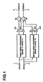
- FIG. 1 is a block diagram illustrating an apparatus according to this embodiment.
- the sound image localisation apparatus (the virtual speaker treatment apparatus) includes first and second input terminals 1 and 2 to which an audio signal is input, a first output terminal 3 connected to a left speaker SPL and a second output terminal 4 connected to a right speaker SPR.
- a 2-channel stereophonic signal is exemplarily shown as an audio signal in Figure 1, the audio signal instead may be a monophonic signal.
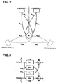
- Figure 2 shows an arrangement of the speakers SPL and SPR.
- a pair of speakers i.e., a left speaker SPL and a right speaker SPR .
- the sound image localization apparatus makes a listener M recognize a sound image at the predetermined position P.
- the position P is located away at an angle ⁇ in a circumferential direction (i.e., counter-clockwise) from the front F of the listener M
- this embodiment of the present invention includes (1) localizing sound image (a virtual speaker) at a first localization a position P1 which is in the vicinity of the predetermined position P and located at an angle ⁇ 1 in the circumferential direction away from the front F of the listener wherein ⁇ 1 ⁇ ⁇ ; and (2) localizing a sound image (a virtual speaker) at a second localization position P2 which is in the vicinity of the predetermined position P and located at an angle ⁇ 2 in the circumferential direction away from the front F of the listener wherein ⁇ 2 > ⁇ .
- this embodiment of the present invention when the position P is located at an angle - ⁇ in another circumferential direction (i.e., clockwise) away from the front F of the listener, this embodiment of the present invention includes (1) localizing a sound image (a virtual speaker) at a first localization position P1 which is in the vicinity of the predetermined position P and located at an angle - ⁇ 1 in the circumferential direction away from the front F of the listener; and (2) localizing sound image (a virtual speaker) at a second localization position P2 which is in the vicinity of the predetermined position P and located at an angle - ⁇ 2 in the circumferential direction away from the front F of the listener.
- a sound image a virtual speaker
- the difference between ⁇ and ⁇ 1 and the difference between ⁇ and ⁇ 2 may be the same or different.
- the difference between ⁇ and ⁇ 1 or between ⁇ and ⁇ 2 may be any suitable amount of angle, and typically, it may be about 30 degrees or less.
- the sound image localization apparatus includes a first signal-processing means (a first virtual speaker treatment means) 11 and a second signal-processing means (a second virtual speaker treatment means) 12 .
- the first and the second means are connected to input terminals 1 and 2 .
- the first signal-processing means 11 is used for localising the sound image at a first localization position P1 and outputs a first L-signal for a left speaker SPL and a first R-signal for a right speaker SPR .
- the second signal-processing means 12 is used for localizing the sound image at a second localisation position P2 and outputs a second L-signal for a left speaker SPL and a second R-signal for a right speaker SPR .
- the first and the second signal-processing means 11 and 12 are typically signal-processing circuits.
- the means 11 and 12 may be a "lattice type” filter or a "shuffler type” filter.
- the sound image localization apparatus may include a pair of lattice type filters or a pair of shuffler type filters.
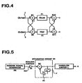
- a lattice type filter includes: (i) a first L-filtering portion (a first L-signal-processing portion) F1L , which is connected to a first input terminal 1 and outputs an output signal for a left speaker SPL; (ii) a first R-filtering portion (a first R-signal-processing portion) F1R, which is connected td a first input terminal 1 and outputs an output signal for a right speaker SPR; (iii) a second L-filtering portion (a second L-signal-processing portion) F2L, which is connected to a second input terminal 2 and outputs an output signal for a left speaker SPL; (iv) a second R-filtering portion (a second R-signal-processing portion) F2R, which is connected to a second input terminal 2 and outputs an output signal for a right speaker SPR; (v) an adding means M8 which adds output signals of a first and a second L-filtering portions F1L
- a transfer function of a first L-filtering portion F1L, a first R-filtering portion F1R, a second L-filtering portion F2L and a second R-filtering portion F2R is defined as H 11, H 12 , H 21 and H 22 , respectively. The details of the transfer function are described below.
- transfer functions H 11 , H 12 , H 21 and H 22 of the first L-filtering portion F1L, the first R-filtering portion F1R, the second L-filtering portion F2L and the second R-filtering portion F2R are obtained by using head-related transfer functions h LL , h LR , h RL , h RR , h L'L , h L'R , h R'L and h R'R .
- h LL is a head-related transfer function from the left speaker SPL to a left ear of the listener M
- h LR is a head-related transfer function from the left speaker SPL to a right ear of the listener M
- h RL is a head-related transfer function from the right speaker SPR to a left ear of the listener M
- h RR is a head-related transfer function from the right speaker SPR to a right ear of the listener M
- h L'L is a head-related transfer function from the virtual left speaker ZL to a left ear of the listener M
- h L'R is a head-related transfer function from the virtual left speaker ZL to a right ear of the listener M
- h R'L is a head-related transfer function from the virtual right speaker ZR to a left ear of the listener M
- h R'R is a head-related transfer function from the virtual right speaker ZR to a right ear of the listener M
- a matrix [h] of the head-related transfer functions from the speakers SPL and SPR to the ears of the listener M a matrix [h'] of the head-related transfer functions from the virtual speakers ZL and ZR to the ears of the listener M, and a matrix [H] of the lattice type filter.
- a shuffler type filter includes: a first filtering portion (a first signal-processing portion) F1 ; a second filtering portion (a second signal-processing portion) F2 ; an adding means M1 which adds audio signals input to the first and second terminals 1 and 2 and inputs the added signal to the first filtering portion F1 ; a subtract means M2 which calculates a differential signal of the audio signals input to the first and second terminals 1 and 2 and inputs the differential signal to the second filtering portion F2 ; an adding means M10 which adds output signals of the first and the second filtering portions F1 and F2 so as to produce a first L-processed signal or a second L-processed signal; a subtract means M11 which subtracts output signal of the second filtering portion F2 from that of the first filtering portion F1 so as to produce a first R-processed signal or a second R-processed signal.
- the shuffler type filter is used in the case where the left and the right speakers SPL and SPR and the left and the right sound image (virtual speakers) ZL and ZR are symmetrically arranged with respect to the listener M.
- transfer functions H SUM and H DIF of the first and the second filtering portions F1 and F2 will be described.
- the transfer functions H SUM and H DIF can be obtained by using the above-mentioned head-related transfer functions h LL , h LR , h RL , h RR , h L'L , h L'R , h R'L and h R'R as follows:
- H SUM (h a' +h b' ) / (h a +h b )
- H DIF (h a' -h b' ) / (h a -h b )
- K1L and K1R respectively denotes a first L-coefficient multiplying means and a first R-coefficient multiplying means.
- the first L- and R-coefficient multiplying means K1L and K1R respectively multiplies the first L-processed signal and the first R-processed signal (which signals are from the first signal-processing means 11 ) by a coefficient k.
- the coefficient k arbitrarily varies in the range of 0 to 1.
- K2L and K2R respectively denotes a second L-coefficient multiplying means and a second R-coefficient multiplying means.
- the second L- and R-coefficient multiplying means K2L and K2R respectively multiplies the second L-processed signal and the second R-processed signal (which signals are from the second signal-processing means 12 ) by a coefficient 1-k.
- a spectrum of the coefficient k has 1/f characteristics. Since the 1/f characteristics provides a physiological nature, an unnatural feeling of a listener can be eliminated by using the coefficient having 1/f characteristics. A method for producing the coefficient having 1/f characteristics will be described below.
- the method includes outputting as a random signal an M-sequence signal from a random signal generator (e.g., a digital signal processor) PR.
- the signal is formed to be a pulse having rectangular shape, height of 1, and random width and pitch.
- the M-sequence signal is multiplied by a coefficient a o in a scaling portion SC1 so as to reduce a possibility that an output value in the succeeding step exceeds 1, and then, as shown in Figure 6B , integrated with respect to time in an integration circuit SK .
- the integration circuit SK includes: a delay circuit J which delays an input signal by one sampling period; a coefficient multiplying means K4 which multiplies an output of the circuit J by a coefficient b 1 ; an adding means (e.g., mixer) M4 which adds an output of the coefficient multiplying means K4 to the input signal to the integration circuit SK .
- the output signal from the integration circuit SK is supplied to an overflow limiter L having a maximum limit value of 1, so as to produce a coefficient k.
- the scaling portion SC1 and the overflow limiter L can be omitted.
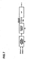
- the method includes supplying an audio signal (2-channel stereophonic signal in Figure 7) to a signal-selecting circuit (e.g., an adding and subtracting circuit) SE and selecting a signal for producing a coefficient from a signal of one of the channels, an added signal of the both channel, or a differential signal of the both channel. Then, the selected signal (shown in Figure 8A ) is squared by a squaring circuit SQ as shown in Figure 8B.
- a signal-selecting circuit e.g., an adding and subtracting circuit
- the squared signal is multiplied by an appropriate coefficient in a scaling portion SC2 so as to reduce a possibility that an output value in the succeeding step exceeds 1. Then, an output signal from the scaling portion SC2 is processed through a low pass filter LPF having a cut-off frequency of about 10 Hz so as to produce a coefficient k ( Figure 8C ).
- M6 and M7 respectively denotes an adding means (e.g., a mixer).
- the adding means M6 adds the first L-processed signal and the second L-processed signal both of which have been multiplied by the coefficient, and supplies the added signal to the left speaker SPL.
- the adding means M7 adds the first R-processed signal and the second R-processed signal both of which have been multiplied by the coefficient, and supplies the added signal to the right speaker SPR.
- this embodiment of the present invention includes producing, by the first signal-processing means 11, the first L-processed signal and the first R-processed signal for localising the sound image at the first localization position P1 which is in the vicinity of the predetermined position P and located at an angle ⁇ 1 (e.g., 90 degrees) counter-clockwise away from the front F of the listener; and producing, by the second signal-processing means 12, the second L-processed signal and the second R-processed signal for localizing the sound image at the second localization position P2 which is in the vicinity of the predetermined position P and located at an angle ⁇ 2 (e.g., 150 degrees) counter-clockwise away from the front F of the listener.
- ⁇ 1 e.g. 90 degrees
- the first L-processed signal and the first R-processed signal are multiplied by a coefficient k (which randomly varies in the range of 0 to 1), and simultaneously the second L-processed signal and the second R-processed signal are multiplied by a coefficient 1-k.
- the multiplied first L-processed signal and the multiplied second L-processed signal are added by the adding means M6 so as to be supplied to the left speaker SPL, and simultaneously the multiplied first R-processed signal and the multiplied second R-processed signal are added by the adding means M7 so as to be supplied to the right speaker SPR.
- the first and the second L-processed signals added in a random ratio are supplied to the left speaker SPL
- the first and the second R-processed signals added in a random ratio are supplied to the right speaker SPR
- the speakers SPL and SPR output a sound wave.
- sound image is localized at a first and a second localization positions P1 and P2.
- a sound volume from the first and the second localization positions P1 and P2 is randomly varied.
- the coefficient k has 1/f characteristics
- the sound volume variation from the first and the second localisation positions P1 and P2 is physiologically natural, thereby providing the listener M with a further natural feeling.
- an apparatus and a method for localising sound image which make a listener clearly recognise that the sound image is at the predetermined position and provide a listener with a natural feeling, can be obtained.
Landscapes
- Engineering & Computer Science (AREA)
- Multimedia (AREA)
- Physics & Mathematics (AREA)
- Acoustics & Sound (AREA)
- Signal Processing (AREA)
- Stereophonic System (AREA)
Claims (7)
- Ein Verfahren zur Lokalisierung eines Schallbildes, mit den folgenden Schritten:wobei wenn die vorgegebene Position sich in einem Winkel in umlaufender Richtung weg von der Vorderseite (F) des Hörers (M) befindet, dann ist die erste Lokalisierungsposition (P1) in der Nähe der vorgegebenen Position (P) und befindet sich in einem Winkel 1 in umlaufender Richtung weg von der Vorderseite (F) des Hörers (M), wobei 1 < , und die zweite Lokalisierungsposition (P2) ist in der Nähe der vorgegebenen Position (P) und befindet sich in einem Winkel 2 in umlaufender Richtung weg von der Vorderseite (F) des Hörers (M), wobei 2 > ,Anordnen eines linken Lautsprechers (SPL) und eines rechten Lautsprechers (SPR) vor einem Hörer;Ausführen eines Schallbildlokalisierungsprozess an einem Audiosignals, durch Herstellen eines ersten verarbeiteten Signals, welches das Schallbild an einer ersten Lokalisierungsposition (P1) lokalisiert, und eines zweiten verarbeiteten Signals, welches das Schallbild an einer zweiten Lokalisierungsposition (P2) lokalisiert;Multiplizieren eines der ersten und zweiten verarbeiteten Signale mit einem Koeffizienten k, der in einem Bereich von 0 bis 1 variiert;Multiplizieren des anderen der ersten und zweiten verarbeiteten Signale mit einem Koeffizienten 1-k;Addieren des verarbeiteten Signals, das mit dem Koeffizienten k multipliziert wurde, und des verarbeiteten Signals, das mit dem Koeffizienten 1-k multipliziert wurde; undZuführen des verarbeiteten Signals zum linken und rechten Lautsprecher (SPL, SPR), um das Schallbild an einer vorgegebenen Position (P) zu lokalisieren;
das Verfahren dadurch gekennzeichnet, dass:der Schritt zur Multiplikation mit dem Koeffizienten k durchgeführt wird mit einem Koeffizienten der zufallsbedingt im Bereich 0 bis 1 variiert. - Verfahren nach Anspruch 1, wobei das Spektrum des Koeffizienten k eine 1/f-Charakteristik hat.
- Verfahren nach Anspruch 1, ferner umfassend die Herstellung des Koeffizienten k durch Erzeugung eines Zufallssignals mit rechteckiger Pulsform, gleichförmiger Höhe und zufälliger Pulsweite und -abstand, und Integrieren des Zufallssignals in einem Integrationsschaltkreis (SK: J, K4, M4).
- Verfahren nach Anspruch 1, ferner umfassend die Herstellung des Koeffizienten k durch das Quadrieren des Audiosignals mit einem Quadrierer (SQ), und Filtern des quadrierten Signals mit einem Tiefpassfilter (LPF).
- Verfahren nach Anspruch 4, ferner umfassend einen Schritt zum Herstellen des Koeffizienten k unter Verwendung eines Signals, wobei das Audiosignal ein stereophones Zweikanalsignal ist, und das Signal zum Herstellen des Koeffizienten k ausgewählt ist von dem einen oder dem anderen der Kanalsignale, der Summe der beiden Kanalsignale und der Differenz der beiden Kanalsignale.
- Eine Vorrichtung zur Lokalisierung eines Schallbildes, umfassend:wobei wenn die vorgegebene Position (P) sich in einem Winkel in einer umlaufender Richtung weg von der Vorderseite (F) des Hörers (M) befindet, dann ist die erste Lokalisierungsposition (P1) in der Nähe der vorgegebenen Position und befindet sich in einem Winkel 1 in der umlaufenden Richtung weg von der Vorderseite (F) des Hörers (M), wobei 1 < , und die zweite Lokalisierungsposition (P2) ist in der Nähe der vorgegebenen Position (P) und befindet sich in einem Winkel 2 in umlaufender Richtung weg von der Vorderseite (F) des Hörers (M), wobei 2 > ,einen linken und einem rechten Lautsprecher (SPL, SPR), die vor einem Hörer anzuordnen sind;Mittel (11, 12) zur Durchführung eines Schallbildlokalisierungsprozesses an einem Audiosignals, umfassend Mittel (11) zum Herstellen eines ersten verarbeiteten Signals, welches das Schallbild an einer ersten Lokalisierungsposition (P1) lokalisiert, und Mittel (12) zum Herstellen eines zweiten verarbeiteten Signals, welches das Schallbild an einer zweiten Lokalisierungsposition (P2) lokalisiert;Mittel zum Herstellen eines Koeffizienten k, der in einem Bereich von 0 bis 1 variiert;Mittel (K1L, K1R) zum Multiplizieren eines der ersten und zweiten verarbeiteten Signale mit dem Koeffizienten k;Mittel (K2L, K2R) zum Multiplizieren des anderen der ersten und zweiten verarbeiteten Signale mit einem Koeffizienten 1-k;Mittel (M6, M7) zum Addieren des verarbeiteten Signals, das mit dem Koeffizienten k multipliziert wurde, mit dem verarbeiteten Signal, das mit dem Koeffizienten 1-k multipliziert wurde, und zum Zuführen des addierten Signals zum den linken und rechten Lautsprechern (SPL, SPR), um das Schallbild an einer vorgegebenen Position (P) zu lokalisieren;
die Vorrichtung dadurch gekennzeichnet, dass:die Mittel zum Herstellen eines Koeffizienten k Mittel (PR, SC1, SK, L; SE, SQ, SC2, LPF) sind, die als Koeffizienten k einen Koffizienten herstellen, der zufallsbedingt im Bereich von 0 bis 1 variiert. - Audiosignalprozessor, umfassend:wobei die Prozessormittel umfassen:Prozessormittel (11, 12, K1L-K2R, M6, M7) zur Durchführung eines Schallbildlokalisierungsprozesses an einem Audiosignals, um ein verarbeitetes Signal herzustellen; undZuführungsmittel (3, 4) zum Zuführen des verarbeiteten Signals zu linken und rechten Lautsprechern (SPL, SPR), um ein lokalisiertes Schallbild an einer vorgegebenen Position (P) herzustellen;wobei, wenn die vorgegebene Position (P) sich in einem Winkel in einer umlaufender Richtung weg von der Vorderseite (F) des Hörers (M) befindet, dann ist die erste Lokalisierungsposition (P1) in der Nähe der vorgegebenen Position und befindet sich in einem Winkel 1 in der umlaufenden Richtung weg von der Vorderseite (F) des Hörers (M), wobei 1 < , und die zweite Lokalisierungsposition (P2) ist in der Nähe der vorgegebenen Position (P) und befindet sich in einem Winkel 2 in umlaufender Richtung weg von der Vorderseite (F) des Hörers (M), wobei 2 >;Mittel (11) zum Herstellen eines ersten verarbeiteten Signals, welches ein lokalisiertes Schallbild an einer ersten Lokalisierungsposition (P1) lokalisiert;Mittel (12) zum Herstellen eines zweiten verarbeiteten Signals, welches ein lokalisiertes Schallbild an einer zweiten Lokalisierungsposition (P2) lokalisiert;Mittel (K1L, K1R) zum Multiplizieren eines der ersten und zweiten verarbeiteten Signale mit einem Koeffizienten k;Mittel (K2L, K2R) zum Multiplizieren des anderen Signals mit einem Koeffizienten 1-k;Mittel (M6, M7) zum Addieren des verarbeiteten Signals, das mit dem Koeffizienten k multipliziert wurde, mit dem verarbeiteten Signal, das mit dem Koeffizienten 1-k multipliziert wurde, und zum Ausgeben des addierten Signals als das verarbeitete Signal an die Zuführungsmittel (3, 4);
der Audiosignalprozessor dadurch gekennzeichnet, durch:Mittel (PR, SC1, SK, L; SE, SQ, SC2, LPF) zum Herstellen des Koeffizienten k als Koeffizienten k, der zufallsbedingt im Bereich von 0 bis 1 variiert.
Applications Claiming Priority (4)
| Application Number | Priority Date | Filing Date | Title |
|---|---|---|---|
| JP2651298 | 1998-01-23 | ||
| JP02651298A JP3233275B2 (ja) | 1998-01-23 | 1998-01-23 | 音像定位処理方法及びその装置 |
| JP3430198 | 1998-01-30 | ||
| JP10034301A JPH11220800A (ja) | 1998-01-30 | 1998-01-30 | 音像移動方法及びその装置 |
Publications (3)
| Publication Number | Publication Date |
|---|---|
| EP0932325A2 EP0932325A2 (de) | 1999-07-28 |
| EP0932325A3 EP0932325A3 (de) | 2000-11-29 |
| EP0932325B1 true EP0932325B1 (de) | 2005-04-27 |
Family
ID=26364297
Family Applications (1)
| Application Number | Title | Priority Date | Filing Date |
|---|---|---|---|
| EP99300468A Expired - Lifetime EP0932325B1 (de) | 1998-01-23 | 1999-01-22 | Vorrichtung und Verfahren zur Schallbildlokalisierung |
Country Status (4)
| Country | Link |
|---|---|
| US (1) | US6504934B1 (de) |
| EP (1) | EP0932325B1 (de) |
| CN (1) | CN1151704C (de) |
| DE (1) | DE69924896T2 (de) |
Families Citing this family (45)
| Publication number | Priority date | Publication date | Assignee | Title |
|---|---|---|---|---|
| US7242782B1 (en) * | 1998-07-31 | 2007-07-10 | Onkyo Kk | Audio signal processing circuit |
| JP3624805B2 (ja) * | 2000-07-21 | 2005-03-02 | ヤマハ株式会社 | 音像定位装置 |
| CN1993002B (zh) * | 2005-12-28 | 2010-06-16 | 雅马哈株式会社 | 声像定位设备 |
| US8041057B2 (en) * | 2006-06-07 | 2011-10-18 | Qualcomm Incorporated | Mixing techniques for mixing audio |
| JP5214920B2 (ja) * | 2007-07-24 | 2013-06-19 | 株式会社東芝 | 超音波診断装置及び超音波診断装置の音響出力方法 |
| US8498667B2 (en) * | 2007-11-21 | 2013-07-30 | Qualcomm Incorporated | System and method for mixing audio with ringtone data |
| US8660280B2 (en) * | 2007-11-28 | 2014-02-25 | Qualcomm Incorporated | Methods and apparatus for providing a distinct perceptual location for an audio source within an audio mixture |
| US8515106B2 (en) * | 2007-11-28 | 2013-08-20 | Qualcomm Incorporated | Methods and apparatus for providing an interface to a processing engine that utilizes intelligent audio mixing techniques |
| US8572513B2 (en) | 2009-03-16 | 2013-10-29 | Apple Inc. | Device, method, and graphical user interface for moving a current position in content at a variable scrubbing rate |
| JP2011010276A (ja) * | 2009-05-22 | 2011-01-13 | Sanyo Electric Co Ltd | 画像再生装置及び撮像装置 |
| US9100766B2 (en) * | 2009-10-05 | 2015-08-04 | Harman International Industries, Inc. | Multichannel audio system having audio channel compensation |
| KR101844511B1 (ko) | 2010-03-19 | 2018-05-18 | 삼성전자주식회사 | 입체 음향 재생 방법 및 장치 |
| KR101764175B1 (ko) | 2010-05-04 | 2017-08-14 | 삼성전자주식회사 | 입체 음향 재생 방법 및 장치 |
| US10706096B2 (en) | 2011-08-18 | 2020-07-07 | Apple Inc. | Management of local and remote media items |
| US9002322B2 (en) | 2011-09-29 | 2015-04-07 | Apple Inc. | Authentication with secondary approver |
| WO2013103256A1 (ko) * | 2012-01-05 | 2013-07-11 | 삼성전자 주식회사 | 다채널 음향 신호의 정위 방법 및 장치 |
| BR112015013154B1 (pt) | 2012-12-04 | 2022-04-26 | Samsung Electronics Co., Ltd | Aparelho fornecedor de áudio, e método fornecedor de áudio |
| WO2014143776A2 (en) | 2013-03-15 | 2014-09-18 | Bodhi Technology Ventures Llc | Providing remote interactions with host device using a wireless device |
| WO2015183366A1 (en) | 2014-05-30 | 2015-12-03 | Apple, Inc. | Continuity |
| US10339293B2 (en) | 2014-08-15 | 2019-07-02 | Apple Inc. | Authenticated device used to unlock another device |
| WO2016036510A1 (en) | 2014-09-02 | 2016-03-10 | Apple Inc. | Music user interface |
| US20170257721A1 (en) * | 2014-09-12 | 2017-09-07 | Sony Semiconductor Solutions Corporation | Audio processing device and method |
| CN107251578B (zh) * | 2015-02-25 | 2018-11-06 | 株式会社索思未来 | 信号处理装置 |
| DK179186B1 (en) | 2016-05-19 | 2018-01-15 | Apple Inc | REMOTE AUTHORIZATION TO CONTINUE WITH AN ACTION |
| DK201670622A1 (en) | 2016-06-12 | 2018-02-12 | Apple Inc | User interfaces for transactions |
| US10992795B2 (en) | 2017-05-16 | 2021-04-27 | Apple Inc. | Methods and interfaces for home media control |
| US11431836B2 (en) | 2017-05-02 | 2022-08-30 | Apple Inc. | Methods and interfaces for initiating media playback |
| US10928980B2 (en) | 2017-05-12 | 2021-02-23 | Apple Inc. | User interfaces for playing and managing audio items |
| CN111343060B (zh) | 2017-05-16 | 2022-02-11 | 苹果公司 | 用于家庭媒体控制的方法和界面 |
| US12526361B2 (en) | 2017-05-16 | 2026-01-13 | Apple Inc. | Methods for outputting an audio output in accordance with a user being within a range of a device |
| CN109065010A (zh) * | 2018-08-23 | 2018-12-21 | 张德明 | 一种具同台联唱模式的k歌系统和k歌方法 |
| CA3131489A1 (en) | 2019-02-27 | 2020-09-03 | Louisiana-Pacific Corporation | Fire-resistant manufactured-wood based siding |
| US11010121B2 (en) | 2019-05-31 | 2021-05-18 | Apple Inc. | User interfaces for audio media control |
| KR102436985B1 (ko) | 2019-05-31 | 2022-08-29 | 애플 인크. | 오디오 미디어 제어를 위한 사용자 인터페이스 |
| US10904029B2 (en) | 2019-05-31 | 2021-01-26 | Apple Inc. | User interfaces for managing controllable external devices |
| DK201970533A1 (en) | 2019-05-31 | 2021-02-15 | Apple Inc | Methods and user interfaces for sharing audio |
| US11079913B1 (en) | 2020-05-11 | 2021-08-03 | Apple Inc. | User interface for status indicators |
| US11392291B2 (en) | 2020-09-25 | 2022-07-19 | Apple Inc. | Methods and interfaces for media control with dynamic feedback |
| EP4334811B1 (de) | 2021-06-06 | 2025-11-19 | Apple Inc. | Benutzerschnittstellen für audiorouting |
| US11847378B2 (en) | 2021-06-06 | 2023-12-19 | Apple Inc. | User interfaces for audio routing |
| US12596520B2 (en) | 2021-09-24 | 2026-04-07 | Apple Inc. | Media controls user interface |
| US12563299B2 (en) | 2022-04-04 | 2026-02-24 | Apple Inc. | User interfaces for camera sharing |
| US12379827B2 (en) | 2022-06-03 | 2025-08-05 | Apple Inc. | User interfaces for managing accessories |
| US12321574B2 (en) | 2022-09-02 | 2025-06-03 | Apple Inc. | Content output devices and user interfaces |
| US12615491B2 (en) | 2022-09-06 | 2026-04-28 | Apple Inc. | Interfaces for device interactions |
Family Cites Families (6)
| Publication number | Priority date | Publication date | Assignee | Title |
|---|---|---|---|---|
| JP3059191B2 (ja) | 1990-05-24 | 2000-07-04 | ローランド株式会社 | 音像定位装置 |
| US5274708A (en) * | 1992-06-01 | 1993-12-28 | Fusan Labs, Inc. | Digital stereo sound enhancement unit and method |
| DE69433258T2 (de) | 1993-07-30 | 2004-07-01 | Victor Company of Japan, Ltd., Yokohama | Raumklangsignalverarbeitungsvorrichtung |
| US5440638A (en) * | 1993-09-03 | 1995-08-08 | Q Sound Ltd. | Stereo enhancement system |
| BE1008027A3 (nl) * | 1994-01-17 | 1995-12-12 | Philips Electronics Nv | Signaalcombinatieschakeling, signaalbewerkingsschakeling voorzien van de signaalcombinatieschakeling, stereofonische audioweergave-inrichting voorzien de signaalbewerkingsschakeling, alsmede een audio-visuele weergave-inrichting voorzien van de stereofonische audioweergave-inrichting. |
| JP3367625B2 (ja) | 1995-01-26 | 2003-01-14 | 日本ビクター株式会社 | 音像定位制御装置 |
-
1999
- 1999-01-22 DE DE69924896T patent/DE69924896T2/de not_active Expired - Lifetime
- 1999-01-22 CN CNB991013662A patent/CN1151704C/zh not_active Expired - Fee Related
- 1999-01-22 US US09/235,483 patent/US6504934B1/en not_active Expired - Fee Related
- 1999-01-22 EP EP99300468A patent/EP0932325B1/de not_active Expired - Lifetime
Also Published As
| Publication number | Publication date |
|---|---|
| CN1235505A (zh) | 1999-11-17 |
| DE69924896T2 (de) | 2005-09-29 |
| EP0932325A3 (de) | 2000-11-29 |
| DE69924896D1 (de) | 2005-06-02 |
| CN1151704C (zh) | 2004-05-26 |
| EP0932325A2 (de) | 1999-07-28 |
| US6504934B1 (en) | 2003-01-07 |
Similar Documents
| Publication | Publication Date | Title |
|---|---|---|
| EP0932325B1 (de) | Vorrichtung und Verfahren zur Schallbildlokalisierung | |
| US7177431B2 (en) | Dynamic decorrelator for audio signals | |
| US6111958A (en) | Audio spatial enhancement apparatus and methods | |
| US7440575B2 (en) | Equalization of the output in a stereo widening network | |
| EP0977464B1 (de) | Tonsignalverarbeitungsschaltung | |
| EP0858243B1 (de) | Raumklangkanal, Kodierung und Dekodierung | |
| US6577736B1 (en) | Method of synthesizing a three dimensional sound-field | |
| EP1194007A2 (de) | Verfahren und Signalverarbeitungsgerät zur Umwandlung von Stereosignalen für Kopfhörer | |
| EP0991298A2 (de) | Verfahren zur Lokalisierung von Schallbild aus von Zuhörerkopf mit einem Kopfhörer | |
| US6504933B1 (en) | Three-dimensional sound system and method using head related transfer function | |
| JP2000050400A (ja) | 左,右両耳用のオーディオ信号を音像定位させるための処理方法 | |
| US5844993A (en) | Surround signal processing apparatus | |
| EP0917400B1 (de) | Vorrichtung und Verfahren zur Schallbildlokalisierung | |
| US8064607B2 (en) | Method for producing more than two electric time signals from one first and one second electric time signal | |
| KR20120062727A (ko) | 스테레오포닉 또는 슈도-스테레오포닉 오디오 신호의 개선 장치 및 방법 | |
| KR100437174B1 (ko) | 스테레오음향시스템 | |
| EP1054574A1 (de) | Vorrichtung zur schallbildlokalisierung | |
| JP3547813B2 (ja) | 音場生成装置 | |
| JP2956545B2 (ja) | 音場制御装置 | |
| US5604810A (en) | Sound field control system for a multi-speaker system | |
| US20060008100A1 (en) | Apparatus and method for producing 3D sound | |
| JP4540290B2 (ja) | 入力信号を音像定位させて三次元空間を移動させる方法 | |
| JP3233275B2 (ja) | 音像定位処理方法及びその装置 | |
| JP4371622B2 (ja) | 疑似ステレオ回路 | |
| KR100741302B1 (ko) | 사운드들을 발생시키기 위한 시스템 |
Legal Events
| Date | Code | Title | Description |
|---|---|---|---|
| PUAI | Public reference made under article 153(3) epc to a published international application that has entered the european phase |
Free format text: ORIGINAL CODE: 0009012 |
|
| AK | Designated contracting states |
Kind code of ref document: A2 Designated state(s): DE FR GB |
|
| AX | Request for extension of the european patent |
Free format text: AL;LT;LV;MK;RO;SI |
|
| PUAL | Search report despatched |
Free format text: ORIGINAL CODE: 0009013 |
|
| AK | Designated contracting states |
Kind code of ref document: A3 Designated state(s): AT BE CH CY DE DK ES FI FR GB GR IE IT LI LU MC NL PT SE |
|
| AX | Request for extension of the european patent |
Free format text: AL;LT;LV;MK;RO;SI |
|
| 17P | Request for examination filed |
Effective date: 20001204 |
|
| AKX | Designation fees paid |
Free format text: DE FR GB NL |
|
| RBV | Designated contracting states (corrected) |
Designated state(s): DE FR GB |
|
| 17Q | First examination report despatched |
Effective date: 20031229 |
|
| GRAP | Despatch of communication of intention to grant a patent |
Free format text: ORIGINAL CODE: EPIDOSNIGR1 |
|
| RBV | Designated contracting states (corrected) |
Designated state(s): DE FR GB NL |
|
| GRAS | Grant fee paid |
Free format text: ORIGINAL CODE: EPIDOSNIGR3 |
|
| GRAA | (expected) grant |
Free format text: ORIGINAL CODE: 0009210 |
|
| AK | Designated contracting states |
Kind code of ref document: B1 Designated state(s): DE FR GB NL |
|
| PG25 | Lapsed in a contracting state [announced via postgrant information from national office to epo] |
Ref country code: NL Free format text: LAPSE BECAUSE OF FAILURE TO SUBMIT A TRANSLATION OF THE DESCRIPTION OR TO PAY THE FEE WITHIN THE PRESCRIBED TIME-LIMIT Effective date: 20050427 |
|
| REG | Reference to a national code |
Ref country code: GB Ref legal event code: FG4D |
|
| REF | Corresponds to: |
Ref document number: 69924896 Country of ref document: DE Date of ref document: 20050602 Kind code of ref document: P |
|
| NLV1 | Nl: lapsed or annulled due to failure to fulfill the requirements of art. 29p and 29m of the patents act | ||
| PLBE | No opposition filed within time limit |
Free format text: ORIGINAL CODE: 0009261 |
|
| STAA | Information on the status of an ep patent application or granted ep patent |
Free format text: STATUS: NO OPPOSITION FILED WITHIN TIME LIMIT |
|
| 26N | No opposition filed |
Effective date: 20060130 |
|
| EN | Fr: translation not filed | ||
| PG25 | Lapsed in a contracting state [announced via postgrant information from national office to epo] |
Ref country code: FR Free format text: LAPSE BECAUSE OF FAILURE TO SUBMIT A TRANSLATION OF THE DESCRIPTION OR TO PAY THE FEE WITHIN THE PRESCRIBED TIME-LIMIT Effective date: 20050427 |
|
| REG | Reference to a national code |
Ref country code: DE Ref legal event code: R081 Ref document number: 69924896 Country of ref document: DE Owner name: ONKYO CORP., NEYAGAWA-SHI, JP Free format text: FORMER OWNER: ONKYO CORP., NEYAGAWA, OSAKA, JP Effective date: 20110302 |
|
| REG | Reference to a national code |
Ref country code: DE Ref legal event code: R082 Ref document number: 69924896 Country of ref document: DE |
|
| PGFP | Annual fee paid to national office [announced via postgrant information from national office to epo] |
Ref country code: GB Payment date: 20121228 Year of fee payment: 15 |
|
| PGFP | Annual fee paid to national office [announced via postgrant information from national office to epo] |
Ref country code: DE Payment date: 20130131 Year of fee payment: 15 |
|
| REG | Reference to a national code |
Ref country code: DE Ref legal event code: R119 Ref document number: 69924896 Country of ref document: DE |
|
| GBPC | Gb: european patent ceased through non-payment of renewal fee |
Effective date: 20140122 |
|
| REG | Reference to a national code |
Ref country code: DE Ref legal event code: R119 Ref document number: 69924896 Country of ref document: DE Effective date: 20140801 |
|
| PG25 | Lapsed in a contracting state [announced via postgrant information from national office to epo] |
Ref country code: DE Free format text: LAPSE BECAUSE OF NON-PAYMENT OF DUE FEES Effective date: 20140801 |
|
| PG25 | Lapsed in a contracting state [announced via postgrant information from national office to epo] |
Ref country code: GB Free format text: LAPSE BECAUSE OF NON-PAYMENT OF DUE FEES Effective date: 20140122 |