EP0932327A1 - Appareil de chauffage par hyperfrequences et procede de liaison dans lequel ledit appareil est utilise - Google Patents
Appareil de chauffage par hyperfrequences et procede de liaison dans lequel ledit appareil est utilise Download PDFInfo
- Publication number
- EP0932327A1 EP0932327A1 EP98936703A EP98936703A EP0932327A1 EP 0932327 A1 EP0932327 A1 EP 0932327A1 EP 98936703 A EP98936703 A EP 98936703A EP 98936703 A EP98936703 A EP 98936703A EP 0932327 A1 EP0932327 A1 EP 0932327A1
- Authority
- EP
- European Patent Office
- Prior art keywords
- bonded
- heating apparatus
- generating means
- heat generating
- microwave
- Prior art date
- Legal status (The legal status is an assumption and is not a legal conclusion. Google has not performed a legal analysis and makes no representation as to the accuracy of the status listed.)
- Withdrawn
Links
Images


Classifications
-
- H—ELECTRICITY
- H05—ELECTRIC TECHNIQUES NOT OTHERWISE PROVIDED FOR
- H05B—ELECTRIC HEATING; ELECTRIC LIGHT SOURCES NOT OTHERWISE PROVIDED FOR; CIRCUIT ARRANGEMENTS FOR ELECTRIC LIGHT SOURCES, IN GENERAL
- H05B6/00—Heating by electric, magnetic or electromagnetic fields
- H05B6/64—Heating using microwaves
- H05B6/70—Feed lines
- H05B6/705—Feed lines using microwave tuning
-
- H—ELECTRICITY
- H05—ELECTRIC TECHNIQUES NOT OTHERWISE PROVIDED FOR
- H05B—ELECTRIC HEATING; ELECTRIC LIGHT SOURCES NOT OTHERWISE PROVIDED FOR; CIRCUIT ARRANGEMENTS FOR ELECTRIC LIGHT SOURCES, IN GENERAL
- H05B6/00—Heating by electric, magnetic or electromagnetic fields
- H05B6/64—Heating using microwaves
-
- C—CHEMISTRY; METALLURGY
- C03—GLASS; MINERAL OR SLAG WOOL
- C03C—CHEMICAL COMPOSITION OF GLASSES, GLAZES OR VITREOUS ENAMELS; SURFACE TREATMENT OF GLASS; SURFACE TREATMENT OF FIBRES OR FILAMENTS MADE FROM GLASS, MINERALS OR SLAGS; JOINING GLASS TO GLASS OR OTHER MATERIALS
- C03C27/00—Joining pieces of glass to pieces of other inorganic material; Joining glass to glass other than by fusing
- C03C27/02—Joining pieces of glass to pieces of other inorganic material; Joining glass to glass other than by fusing by fusing glass directly to metal
-
- C—CHEMISTRY; METALLURGY
- C04—CEMENTS; CONCRETE; ARTIFICIAL STONE; CERAMICS; REFRACTORIES
- C04B—LIME, MAGNESIA; SLAG; CEMENTS; COMPOSITIONS THEREOF, e.g. MORTARS, CONCRETE OR LIKE BUILDING MATERIALS; ARTIFICIAL STONE; CERAMICS; REFRACTORIES; TREATMENT OF NATURAL STONE
- C04B37/00—Joining burned ceramic articles with other burned ceramic articles or other articles by heating
- C04B37/001—Joining burned ceramic articles with other burned ceramic articles or other articles by heating directly with other burned ceramic articles
-
- C—CHEMISTRY; METALLURGY
- C04—CEMENTS; CONCRETE; ARTIFICIAL STONE; CERAMICS; REFRACTORIES
- C04B—LIME, MAGNESIA; SLAG; CEMENTS; COMPOSITIONS THEREOF, e.g. MORTARS, CONCRETE OR LIKE BUILDING MATERIALS; ARTIFICIAL STONE; CERAMICS; REFRACTORIES; TREATMENT OF NATURAL STONE
- C04B37/00—Joining burned ceramic articles with other burned ceramic articles or other articles by heating
- C04B37/003—Joining burned ceramic articles with other burned ceramic articles or other articles by heating by means of an interlayer consisting of a combination of materials selected from glass, or ceramic material with metals, metal oxides or metal salts
- C04B37/005—Joining burned ceramic articles with other burned ceramic articles or other articles by heating by means of an interlayer consisting of a combination of materials selected from glass, or ceramic material with metals, metal oxides or metal salts consisting of glass or ceramic material
-
- H—ELECTRICITY
- H05—ELECTRIC TECHNIQUES NOT OTHERWISE PROVIDED FOR
- H05B—ELECTRIC HEATING; ELECTRIC LIGHT SOURCES NOT OTHERWISE PROVIDED FOR; CIRCUIT ARRANGEMENTS FOR ELECTRIC LIGHT SOURCES, IN GENERAL
- H05B6/00—Heating by electric, magnetic or electromagnetic fields
- H05B6/64—Heating using microwaves
- H05B6/647—Aspects related to microwave heating combined with other heating techniques
- H05B6/6491—Aspects related to microwave heating combined with other heating techniques combined with the use of susceptors
-
- H—ELECTRICITY
- H05—ELECTRIC TECHNIQUES NOT OTHERWISE PROVIDED FOR
- H05B—ELECTRIC HEATING; ELECTRIC LIGHT SOURCES NOT OTHERWISE PROVIDED FOR; CIRCUIT ARRANGEMENTS FOR ELECTRIC LIGHT SOURCES, IN GENERAL
- H05B6/00—Heating by electric, magnetic or electromagnetic fields
- H05B6/64—Heating using microwaves
- H05B6/70—Feed lines
-
- H—ELECTRICITY
- H05—ELECTRIC TECHNIQUES NOT OTHERWISE PROVIDED FOR
- H05B—ELECTRIC HEATING; ELECTRIC LIGHT SOURCES NOT OTHERWISE PROVIDED FOR; CIRCUIT ARRANGEMENTS FOR ELECTRIC LIGHT SOURCES, IN GENERAL
- H05B6/00—Heating by electric, magnetic or electromagnetic fields
- H05B6/64—Heating using microwaves
- H05B6/80—Apparatus for specific applications
-
- C—CHEMISTRY; METALLURGY
- C04—CEMENTS; CONCRETE; ARTIFICIAL STONE; CERAMICS; REFRACTORIES
- C04B—LIME, MAGNESIA; SLAG; CEMENTS; COMPOSITIONS THEREOF, e.g. MORTARS, CONCRETE OR LIKE BUILDING MATERIALS; ARTIFICIAL STONE; CERAMICS; REFRACTORIES; TREATMENT OF NATURAL STONE
- C04B2235/00—Aspects relating to ceramic starting mixtures or sintered ceramic products
- C04B2235/65—Aspects relating to heat treatments of ceramic bodies such as green ceramics or pre-sintered ceramics, e.g. burning, sintering or melting processes
- C04B2235/66—Specific sintering techniques, e.g. centrifugal sintering
- C04B2235/667—Sintering using wave energy, e.g. microwave sintering
-
- C—CHEMISTRY; METALLURGY
- C04—CEMENTS; CONCRETE; ARTIFICIAL STONE; CERAMICS; REFRACTORIES
- C04B—LIME, MAGNESIA; SLAG; CEMENTS; COMPOSITIONS THEREOF, e.g. MORTARS, CONCRETE OR LIKE BUILDING MATERIALS; ARTIFICIAL STONE; CERAMICS; REFRACTORIES; TREATMENT OF NATURAL STONE
- C04B2237/00—Aspects relating to ceramic laminates or to joining of ceramic articles with other articles by heating
- C04B2237/02—Aspects relating to interlayers, e.g. used to join ceramic articles with other articles by heating
- C04B2237/10—Glass interlayers, e.g. frit or flux
-
- C—CHEMISTRY; METALLURGY
- C04—CEMENTS; CONCRETE; ARTIFICIAL STONE; CERAMICS; REFRACTORIES
- C04B—LIME, MAGNESIA; SLAG; CEMENTS; COMPOSITIONS THEREOF, e.g. MORTARS, CONCRETE OR LIKE BUILDING MATERIALS; ARTIFICIAL STONE; CERAMICS; REFRACTORIES; TREATMENT OF NATURAL STONE
- C04B2237/00—Aspects relating to ceramic laminates or to joining of ceramic articles with other articles by heating
- C04B2237/30—Composition of layers of ceramic laminates or of ceramic or metallic articles to be joined by heating, e.g. Si substrates
- C04B2237/32—Ceramic
-
- C—CHEMISTRY; METALLURGY
- C04—CEMENTS; CONCRETE; ARTIFICIAL STONE; CERAMICS; REFRACTORIES
- C04B—LIME, MAGNESIA; SLAG; CEMENTS; COMPOSITIONS THEREOF, e.g. MORTARS, CONCRETE OR LIKE BUILDING MATERIALS; ARTIFICIAL STONE; CERAMICS; REFRACTORIES; TREATMENT OF NATURAL STONE
- C04B2237/00—Aspects relating to ceramic laminates or to joining of ceramic articles with other articles by heating
- C04B2237/50—Processing aspects relating to ceramic laminates or to the joining of ceramic articles with other articles by heating
- C04B2237/78—Side-way connecting, e.g. connecting two plates through their sides
Definitions
- the present invention relates to a microwave heating apparatus and a method of bonding objects thereby
- a method of ceramic-to-ceramic bonding is used wherein an intermediate ceramic sealing material is sandwiched between two ceramic materials, the intermediate ceramic sealing material is directly heated by a microwave, and the intermediate ceramic sealing material is used as a bonding material to bond the two ceramic materials (Bonding Technology Data Handbook depending on Type of Material, by Science Forum Inc., Vol. 2 (Ceramic Material Bonding), Page 14).
- the bonding is carried out occasionally in an Ar gas atmosphere to prevent the metal from being oxidized.
- a glass material to be melted and used as an intermediate material is sandwiched between the metal and the ceramic material, the metal is heated by Ar arcs or high-frequency heating to melt the glass material, and the melted glass material is used as a bonding material to bond the metal and the ceramic material.
- the bonding is carried out in a condition wherein an intermediate ceramic sealing material is sandwiched between the two ceramic materials. Since an oxide constituting the intermediate ceramic sealing material is transparent for a microwave, the intermediate ceramic sealing material cannot be heated sufficiently, and the two ceramic materials cannot be bonded to each other, even if the intermediate ceramic sealing material is heated by using the microwave, unless a coupling material having a high resistance is included in the intermediate ceramic sealing material.
- the glass tube is made of glass having a low melting point just as in the case of borosilicate glass or lead glass, the glass tube having such a low melting point can be melted and sealed by an electric furnace.
- the glass tube is made of glass having a high melting point just as in the case of quartz glass, the glass tube having such a high melting point cannot be melted unless it is heated to about 2000°C or more. In order to melt the glass tube, it is necessary to use a special electric furnace capable of heating the glass tube to about 2000°C or more.
- a special electric furnace capable of heating the ceramic material to about 2000°C or more is required just as in the above-mentioned case of melting a glass tube made of quartz glass having a high melting point.
- the heat source can heat and melt a local portion of the glass tube and the like. Since the heat source generates a large amount of heat, it must be cooled. However, since the amount of heat generated by the heat source is large, it is very difficult to cool the heat source. In addition, energy loss generated at the time of the cooling becomes significant. For this reason, when such a tungsten heater or carbon heater is used as a heat source, its energy efficiency becomes extremely low.
- one object of the present invention is to provide a microwave heating apparatus capable of heating materials transparent for microwaves to high temperatures and to provide a method of bonding objects by using the apparatus.
- another object of the present invention is to provide a microwave heating apparatus capable of heating materials transparent for microwaves to high temperatures and to provide a method of bonding objects by using the apparatus in an atmosphere of a rare gas such as Ar gas or in a substantially vacuum condition.
- a microwave heating apparatus of the present invention comprises a microwave generating means for generating a microwave and a heat generating means for absorbing said microwave from said microwave generating means and for generating heat on the basis of said absorbed microwave and, wherein said heat generating means is disposed to substantially cover a predetermined position.
- a method of the present invention of bonding objects to be bonded is that with using a microwave heating apparatus of the present invention, objects to be bonded are disposed at a predetermined distance position from said heat generating means of said apparatus or at a position covered by said heat generating means, and said objects are bonded by using the heat from said heat generating means.
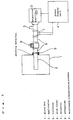
- FIG. 1 is a side view of the microwave heating apparatus in accordance with embodiment 1 of the present invention.
- FIG. 2, being supplementary to FIG. 1, is a side view of the glove box 1 of the microwave heating apparatus.
- the numeral 1 designates a substantially hermetically sealed chamber, that is, a glove box for substantially blocking the entry of outside air.
- the glove box 1 is charged with a predetermined amount of Ar gas.
- the Ar gas charged in the glove box 1 is circulated by a purifier to remove the moisture content in the Ar gas as much as possible, thereby to reduce the dew-point of the Ar gas.
- the numeral 2 designates an applicator, the major portion of which is disposed in the glove box 1.
- a microwave is introduced from a magnetron oscillator 3 described later into the glove box 1 via a waveguide 8 described later, and a standing wave of the microwave is generated to resonate the microwave.
- the numeral 3 designates the magnetron oscillator for generating a microwave.
- the numeral 4 designates a power supply unit for supplying electric power to the magnetron oscillator 3.
- the numeral 5 designates an isolator.
- the isolator 5 prevents the microwave from the magnetron oscillator 3 from returning to the magnetron oscillator 3 after the microwave is reflected by a reflection plate 12 with an adjustment rod described later and the like.
- the numeral 6 designates a stub tuner. This device performs tuning so that the energy of the microwave generated by the magnetron oscillator 3 can be supplied efficiently to the applicator 2.
- the numeral 7 is a detector for detecting energy supplied to the applicator 2 and energy reflected to the magnetron oscillator 3.
- the magnetron oscillator 3, the power supply unit 4, the isolator 5, the stub tuner 6 and the detector 7 are provided outside the glove box 1.
- the numeral 8 designates a waveguide for guiding the microwave from the magnetron oscillator 3 to the applicator 2.
- the numeral 9 designates a microwave transmission window disposed at the opening of the waveguide 8 on the side of the applicator 2 and formed of a high-purity alumina plate for allowing the microwave from the magnetron oscillator 3 to pass through.
- the waveguide 8 is connected to the applicator 2 via the microwave transmission window 9.
- the microwave transmission window 9 at the connection portion is disposed to close the openings of the waveguide 8 and the applicator 2, which are provided in face-to-face relationship. Therefore, the passage of the microwave from the magnetron oscillator 3 is shut off from the outside air.
- the numeral 10 designates a partially passing-through cylindrical susceptor (microwave absorbing material). This susceptor 10 is disposed at the resonance position of the microwave inside the applicator 2 in the glove box 1 so as to substantially cover a predetermined area as shown in FIG. 2, and is used as a means for absorbing the microwave from the magnetron oscillator 3 and for generating radiation heat on the basis of the energy of the absorbed microwave.
- the susceptor 10 is made of silicon carbide (SiC).
- the numeral 11 designates a thermal adiabatic material made of zirconia. This adiabatic material is disposed around the susceptor 10 inside the applicator 2 in the glove box 1 as shown in FIG. 2 to thermally adiabate the susceptor 10.
- an alumina block is also disposed as a thermal adiabatic material 11 so as to cover the thermal adiabatic material 11 made of zirconia, thereby to thermally adiabate the susceptor 10.
- the numeral 12 designates a reflection plate with an adjustment rod. As shown in FIG.
- the reflection plate 12 with the adjustment rod is disposed at one end of the applicator 2, that is, at the end of the applicator 2 on the opposite side of the magnetron oscillator 3, and is used to adjust the distance to the magnetron oscillator 3.
- the reflection plate 12 with the adjustment rod By the movement of the reflection plate 12 with the adjustment rod, the distance between the reflection plate 12 with the adjustment rod and the magnetron oscillator 3 is changed, the microwave becomes a standing wave inside the applicator 2, and the energy of the microwave from the magnetron oscillator 3 is concentrated on the susceptor 10.
- the two ceramic materials 13 When the two ceramic materials 13 are bonded to each other, they are disposed so that they are arranged substantially perpendicular to the straight line extending from the susceptor 10 to the magnetron oscillator 3 and so that the mutual bonding portions of the ceramic materials 13 are covered with the susceptor 10 at the passing-through portion of the susceptor 10 as shown in FIG. 2.
- an intermediate frit material 14 for bonding the two ceramic materials 13 is disposed between the two ceramic materials 13.
- the ceramic materials 13 and the intermediate frit material 14 are disposed so that the intermediate frit material 14 is sandwiched between the two ceramic materials 13.
- CaO-Al 2 O 3 having a melting point of about 1000 to 1500°C is used as the intermediate frit material 14.
- the magnetron oscillator 3 generates a microwave having a predetermined amount of energy.
- the microwave passes the waveguide 8, passes through the microwave transmission window 9, is introduced into the applicator 2, and is absorbed by the susceptor 10 comprising two segments.
- the reflection plate 12 with the adjustment rod has been adjusted so that the resonance portion of the microwave is aligned with the position of the susceptor 10, that is, so that the energy of the microwave becomes maximum at the position of the susceptor 10.
- FIG.5 shows a status before the adjustment
- FIG.6 shows a status where the maximum position of the electric field intensity 100 of a standing wave is disposed at a center of the susceptor 10.
- the susceptor 10 generates radiation heat on the basis of the energy of the absorbed microwave.
- the temperature of the intermediate frit material 14 is raised to a predetermined temperature, that is, the melting point of the intermediate frit material 14, in a short time of several seconds to several minutes.
- the intermediate frit material 14 is melted and used as a bonding material to bond the two ceramic materials 13.
- the intermediate frit material 14 is required to include an inorganic coupling agent for absorbing the microwave.
- the intermediate frit material 14 is made of CaO-Al 2 O 3 as described above and does not include any inorganic coupling agent. Nevertheless, since the intermediate frit material 14 in accordance with embodiment 1 absorbs radiation heat from the susceptor 10 and is heated to a high temperature, the frit material 14 can be melted even when the material does not include any inorganic coupling agent.
- the microwave transmission window 9 is formed of a high-purity alumina plate.
- the microwave transmission window 9 may be formed of a high-purity Teflon plate.
- the thermal adiabatic material 11 made of zirconia is used, and the alumina block is also disposed.
- the zirconia material and the alumina block for the thermal adiabatic materials 11 used as thermal adiabatic means in embodiment 1 may be disposed at places interchanged from each other.
- only the zirconia material or the alumina block may be used for the thermal adiabatic material 11 as the thermal adiabatic means.
- the intermediate frit material 14 is made of CaO-Al 2 O 3 .
- CaO-Al 2 O 3 -SiO 3 or MgO-Al 2 O 3 -SiO 3 may be used for the intermediate frit material 14 used as a sealing material to be melted.
- the intermediate frit material 14 is used and melted by radiation heat from the susceptor 10, and the ceramic materials 13 sandwiching the intermediate frit material 14 are bonded to each other by using the melted intermediate frit material 14.
- the connection portions of the two ceramic materials 13 used as materials to be bonded may be sintered by radiation heat from the susceptor 10 to bond the ceramic materials 13 to each other.
- embodiment 2 A main difference between embodiment 2 and embodiment 1 is that the objects to be bonded by using the above-mentioned heating apparatus of embodiment 1 differ from those to be bonded by the heating apparatus of embodiment 2.
- embodiment 2 only matters different from those in embodiment 1 will be described below.
- FIG. 3 is a side view of the glove box 1 of the microwave heating apparatus in accordance with embodiment 2 of the present invention.
- the applicator 2 has a through hole 16 passing through in the vertical direction in FIG. 3.
- the susceptor 10 is disposed so that the passing-through portion of the susceptor 10 coincides with the through hole 16.
- the microwave heating apparatus in accordance with embodiment 2 of the present invention is provided with an exhaust pipe 17 disposed at a predetermined position above the through hole 16.
- the metal halide to be hermetically sealed in the quartz glass tube 15 is prevented from being oxidized inside the glove box 1 charged with Ar gas, the metal halide is fed into the quartz glass tube 15 having been sealed in advance on one side thereof, and the quartz glass tube 15 is inserted into the through hole 16 with the sealed portion thereof directed downward. With the metal halide kept included, the quartz glass tube 15 is disposed so that its predetermined portion to be sealed is positioned at the portion passing through the susceptor 10. Next, the unsealed upper portion of the quartz glass tube 15 is connected to the exhaust pipe 17. The gas inside the quartz glass tube 15 is exhausted under reduced pressure by a vacuum pump disposed outside the glove box 1 and connected to the exhaust pipe 17.
- the magnetron oscillator 3 After this, the magnetron oscillator 3 generates a microwave having a predetermined amount of energy.
- the microwave passes the waveguide 8, passes through the microwave transmission window 9, is introduced into the applicator 2, and is absorbed by the susceptor 10.
- the susceptor 10 generates radiation heat on the basis of the energy of the absorbed microwave, the quartz glass tube 15 is softened and melted at the predetermined portion, and its softened and melted portion is bonded.
- the quartz glass tube 15 is softened and melted, its softened and melted portion tends to hang down by its own weight. Therefore, the energy of the microwave generated by the magnetron oscillator 3 must be set properly, and/or the time of supplying the energy to the susceptor 10 must be set at an appropriate time.
- the quartz glass tube 15 can be sealed in a short time.
- the amount of heat to be applied to the quartz glass tube 15, that is, the temperature distribution of the quartz glass tube 15 can be adjusted. For example, when the diameter of the through hole 16 in the applicator 2 is increased, and in accordance with this increase, the diameter of the passing-through portion of the susceptor 10 is also increased, the high temperature area of the quartz glass tube 15 becomes smaller and limited. When the clearance between the susceptor 10 and the quartz glass tube 15 is decreased, the high temperature area of the quartz glass tube 15 becomes larger. Therefore, by adjusting the clearance between the susceptor 10 and the quartz glass tube 15, the quartz glass tube 15 can be heated locally, and thermal effects to portions other than the heated portion can be reduced.
- an Ar arc generating Ar burner or the like has been used conventionally to hermetically seal the quartz glass tube 15.
- an Ar burner is used in the glove box 1 in this way, workability is lowered.
- the temperature of the entire glove box 1 increases, the pressure therein also increases. It is thus necessary to perform work efficiently to ensure safety.
- the quartz glass tube 15 is melted and bonded by using the Ar burner, large amounts of silica powder of quartz and very thin thread-like quartz are generated, and these must be removed. However, it is extremely difficult to perform the removal inside the glove box 1.
- the quartz glass tube 15 can be easily hermetically sealed inside the glove box 1 charged with Ar gas without using an Ar burner as described above.
- the microwave heating apparatus in accordance with embodiment 2 of the present invention the above-mentioned metal halide having a high vapor pressure can easily be hermetically sealed in the quartz glass tube 15, and materials extremely undesired to be oxidized can easily be bonded to and hermetically sealed in the quartz glass tube 15.
- the material to be hermetically sealed in the quartz glass tube 15 is a metal halide.
- the material to be hermetically sealed in the quartz glass tube 15 may be mercury, metal and/or metal halide.
- embodiment 3 A main difference between embodiment 3 and embodiment 1 or 2 is that the objects to be bonded by using the above-mentioned heating apparatuses differ from those to be bonded by the heating apparatus of embodiment 3.
- embodiment 3 only matters different from those in embodiment 1 or 2 will be described below.
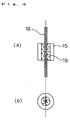
- FIGS. 4a and 4b are views showing the arrangement of the quartz glass tube 15, the metal rod 18 and a graded glass piece 19 when the metal rod 18 undesired to be oxidized is bonded to and sealed in the quartz glass tube 15 by using the microwave heating apparatus in accordance with embodiment 3 of the present invention.
- the graded glass piece 19 is a material to be used to bond the metal rod 18 to the quartz glass tube 15. Its thermal expansion coefficient varies gradually depending on its area; the thermal expansion coefficient on its one side making contact with the quartz glass tube 15 is (1 to 8) ⁇ 10 -7 /°C, and the thermal expansion coefficient on its other side making contact with the metal rod 18 is (10 to 100) ⁇ 10 -7 /°C.
- FIG. 4a is a sectional side view showing the arrangement of the quartz glass tube 15, the metal rod 18 and the graded glass piece 19 described above.
- FIG. 4b is a plan view showing the arrangement of the quartz glass tube 15, the metal rod 18 and the graded glass piece 19.
- the graded glass piece 19 is disposed in the quartz glass tube 15 as shown in FIG. 4a such that its one side having a smaller thermal expansion coefficient makes contact with the quartz glass tube 15 and such that its other side having a larger thermal expansion coefficient makes contact with the metal rod 18.
- the quartz glass tube 15 provided with the metal rod 18 and the graded glass piece 19 is disposed at the passing-through portion of the susceptor 10 of the microwave heating apparatus in accordance with embodiment 3 of the present invention.
- the microwave having a predetermined amount of energy and delivered from the magnetron oscillator 3 is absorbed by the susceptor 10.
- the susceptor 10 generates radiation heat on the basis of the energy of the absorbed microwave to soften and melt the graded glass piece 19.
- the metal rod 18 is bonded to and sealed in the quartz glass tube 15.
- the cylindrical metal rod 18 is used as a metal member of the present invention.
- the metal member of the present invention is not limited to the cylindrical metal rod 18.
- a prism-shaped metal rod or a plate-like metal piece may be used.
- the magnetron oscillator 3 is used as a microwave generating means
- the susceptor 10 is used as a heat generating means
- the thermal adiabatic material 11 is used as a thermal adiabatic means
- the glove box 1 is used as a sealing chamber.
- the intermediate frit material 14 is used in embodiment 1
- the graded glass piece 19 is used in embodiment 3.
- the two ceramic materials 13 are used in embodiment 1
- the quartz glass tube 15 is used in embodiment 2
- the quartz glass tube 15 and the metal rod 18 are used in embodiment 3.
- the glove box 1 is charged with a predetermined amount of Ar gas only.
- the glove box 1 used as a hermetic sealing chamber may be charged with a predetermined amount of a rare gas only, other than Ar gas.
- the two ceramic materials 13, the quartz glass tube 15, or the quartz glass tube 15 and the metal rod 18, used as an object or objects to be bonded, and the graded glass piece 19 used as a sealing material to be melted are disposed at their predetermined positions.
- the user of the microwave heating apparatus of the present invention may manually secure the object(s) to be bonded and/or the sealing material to be melted so that they are disposed at their predetermined positions by using the glove of the glove box 1 used as a sealing chamber.
- the object(s) to be bonded and/or the sealing material to be melted should only be disposed at their predetermined positions.
- the susceptor 10 has a partially passing-through cylindrical shape so as to substantially cover the predetermined position.
- the susceptor 10 used as a heat generating means of the present invention may have a plate-like shape or a shape of a vertically split cylinder.
- the susceptor 10 used as a heat generating means of the present invention should only be a means for absorbing the microwave from the magnetron oscillator 3 used as a microwave generating means and for generating radiation heat on the basis of the energy of the absorbed microwave.
- the shape is thus not limited to a cylindrical shape.
- the susceptor 10 used as the heat generating means of the present invention is not cylindrical, the object(s) to be bonded and/or the sealing material to be melted must be disposed at a predetermined distance position from the susceptor 10 wherein a predetermined amount of heat can be absorbed from the susceptor 10.
- the glove box 1 of the microwave heating apparatus of the present invention is charged with Ar gas, and the two ceramic materials 13 are bonded to each other in the Ar gas atmosphere, or the quartz glass tube 15 is hermetically sealed, or the metal rod 18 is bonded to and sealed in the quartz glass tube 15.
- the apparatus can be used even when the glove box 1 of the apparatus used as a hermetically sealed chamber is charged with a rare gas such as Ar gas, and metals of Mo, W and the like undesired to be oxidized are bonded metal-to-metal in the rare gas atmosphere.
- the above-mentioned metal-to-metal bonding may be carried out in a substantially vacuum condition in the glove box 1 used as a hermetically sealed chamber.
- the object to be bonded is not made of a material like a metal undesired to be oxidized but made of a material like the ceramic material 13 not required to be bonded in the atmosphere of a rare gas such an Ar gas or in a substantially vacuum condition, the object to be bonded is not required to be bonded in the atmosphere of the rare gas such as Ar gas or in the substantially vacuum condition.
- the objects to be bonded can be bonded properly by controlling the energy of the microwave generated by the magnetron oscillator 3, the shape of the susceptor 10 and/or the size of the thermal adiabatic material 11.
- the susceptor 10 is cooled every when one set of the objects to be bonded is bonded.
- FIG.8 shows one exmaple of the cooling method.
- a pipe 23 is inserted into the through hole 16 when cooling, and the above refrigerant or cool window goes through the pipe 23.
- the susceptor 10 which becomes too high temperature is cooled.
- a nozzle 24 is disposed direct under the pipe 23 and the refrigerant and so on is sent by using a valve for closing.
- the pressure in the globe box 1 is made a constant value by using a rotary pump 22 and an adjusting pressure valve 21.
- the reason why the susceptor is cooled every when the objects are bonded is that the heating apparatus of the present invention has high heat adiabatic efficiency and then when the sample is exchanged, the exchanging operation is difficult if the susceptor is too high temperature.
- the present invention can provide a microwave heating apparatus capable of heating materials transparent for microwaves to high temperatures, and can provide a method of bonding objects by using the apparatus.
- the present invention can provide a microwave heating apparatus capable of heating materials transparent for microwaves to high temperatures in an atmosphere of a rare gas, such as Ar gas or in a substantially vacuum condition, and can also provide a method of bonding objects by using the apparatus.
- a rare gas such as Ar gas or in a substantially vacuum condition
- ceramic-to-ceramic bonding, sealing of a quartz glass tube, metal-to-metal bonding of metals having high melting points and undesired to be oxidized, bonding of a metal to a ceramic material or a quartz glass tube, and the like can easily be carried out in an atmosphere of a rare gas, such as Ar gas or in a substantially vacuum condition.
Landscapes
- Chemical & Material Sciences (AREA)
- Engineering & Computer Science (AREA)
- Electromagnetism (AREA)
- Ceramic Engineering (AREA)
- Physics & Mathematics (AREA)
- Organic Chemistry (AREA)
- Materials Engineering (AREA)
- Structural Engineering (AREA)
- Life Sciences & Earth Sciences (AREA)
- Chemical Kinetics & Catalysis (AREA)
- General Chemical & Material Sciences (AREA)
- Geochemistry & Mineralogy (AREA)
- Constitution Of High-Frequency Heating (AREA)
- Ceramic Products (AREA)
Applications Claiming Priority (3)
| Application Number | Priority Date | Filing Date | Title |
|---|---|---|---|
| JP21724297 | 1997-08-12 | ||
| JP21724297 | 1997-08-12 | ||
| PCT/JP1998/003533 WO1999008487A1 (fr) | 1997-08-12 | 1998-08-07 | Appareil de chauffage par hyperfrequences et procede de liaison dans lequel ledit appareil est utilise |
Publications (1)
| Publication Number | Publication Date |
|---|---|
| EP0932327A1 true EP0932327A1 (fr) | 1999-07-28 |
Family
ID=16701089
Family Applications (1)
| Application Number | Title | Priority Date | Filing Date |
|---|---|---|---|
| EP98936703A Withdrawn EP0932327A1 (fr) | 1997-08-12 | 1998-08-07 | Appareil de chauffage par hyperfrequences et procede de liaison dans lequel ledit appareil est utilise |
Country Status (5)
| Country | Link |
|---|---|
| EP (1) | EP0932327A1 (fr) |
| KR (1) | KR20000068751A (fr) |
| CN (1) | CN1236533A (fr) |
| TW (1) | TW449575B (fr) |
| WO (1) | WO1999008487A1 (fr) |
Cited By (2)
| Publication number | Priority date | Publication date | Assignee | Title |
|---|---|---|---|---|
| US7022198B2 (en) * | 2003-03-07 | 2006-04-04 | The United States Of America As Represented By The Secretary Of The Navy | Microwave assisted reactive brazing of ceramic materials |
| US20140224789A1 (en) * | 2013-02-08 | 2014-08-14 | Letourneau University | Method for joining two dissimilar materials and a microwave system for accomplishing the same |
Family Cites Families (3)
| Publication number | Priority date | Publication date | Assignee | Title |
|---|---|---|---|---|
| JPS63239164A (ja) * | 1987-03-27 | 1988-10-05 | 工業技術院長 | セラミックスの接合方法 |
| JPH06174888A (ja) * | 1992-12-08 | 1994-06-24 | Power Reactor & Nuclear Fuel Dev Corp | 核燃料加熱処理装置 |
| JPH07254364A (ja) * | 1994-03-14 | 1995-10-03 | Harrison Denki Kk | 冷陰極放電灯の製造方法 |
-
1998
- 1998-08-07 KR KR1019997003150A patent/KR20000068751A/ko not_active Withdrawn
- 1998-08-07 CN CN98801144A patent/CN1236533A/zh active Pending
- 1998-08-07 WO PCT/JP1998/003533 patent/WO1999008487A1/fr not_active Ceased
- 1998-08-07 EP EP98936703A patent/EP0932327A1/fr not_active Withdrawn
- 1998-08-11 TW TW087113197A patent/TW449575B/zh active
Non-Patent Citations (1)
| Title |
|---|
| See references of WO9908487A1 * |
Cited By (3)
| Publication number | Priority date | Publication date | Assignee | Title |
|---|---|---|---|---|
| US7022198B2 (en) * | 2003-03-07 | 2006-04-04 | The United States Of America As Represented By The Secretary Of The Navy | Microwave assisted reactive brazing of ceramic materials |
| US20140224789A1 (en) * | 2013-02-08 | 2014-08-14 | Letourneau University | Method for joining two dissimilar materials and a microwave system for accomplishing the same |
| US9374853B2 (en) * | 2013-02-08 | 2016-06-21 | Letourneau University | Method for joining two dissimilar materials and a microwave system for accomplishing the same |
Also Published As
| Publication number | Publication date |
|---|---|
| CN1236533A (zh) | 1999-11-24 |
| KR20000068751A (ko) | 2000-11-25 |
| TW449575B (en) | 2001-08-11 |
| WO1999008487A1 (fr) | 1999-02-18 |
Similar Documents
| Publication | Publication Date | Title |
|---|---|---|
| US7226334B2 (en) | Apparatus for making high buffer gas pressure ceramic arc tube | |
| US7358666B2 (en) | System and method for sealing high intensity discharge lamps | |
| EP0932327A1 (fr) | Appareil de chauffage par hyperfrequences et procede de liaison dans lequel ledit appareil est utilise | |
| EP0786798B1 (fr) | Lampe à décharge à micro-ondes sans électrodes et procédé de fabrication d'une telle lampe | |
| JPH11135252A (ja) | マイクロ波を用いた加熱装置およびその装置による接合対象の接合方法 | |
| EP1018391A1 (fr) | Procede et dispositif d'union par fusion de materiaux a point de fusion eleve | |
| US3628846A (en) | Method of making a vapor discharge lamp | |
| HK1021470A (en) | Heater utilizing microwave and bonding method using it | |
| JP2000301371A (ja) | 高融点材料の溶融接合方法およびその装置 | |
| JP6379094B2 (ja) | Luwplのルツボ | |
| KR102416265B1 (ko) | 쿼츠 유리 앰플 실링장치 | |
| CN119136763A (zh) | 用于烧制或烧结工件的熔炉的加热元件和至少有一个此类加热元件的熔炉 | |
| JP3169846B2 (ja) | 無電極放電ランプとその製造方法 | |
| CN103918056B (zh) | 用于luwpl的坩埚 | |
| JPH10295561A (ja) | 真空構造体の排気装置 | |
| JP2002163982A (ja) | 蛍光放電管の製造方法 | |
| JPS62184758A (ja) | セラミツク放電灯 | |
| JPS62250939A (ja) | 原料供給装置 |
Legal Events
| Date | Code | Title | Description |
|---|---|---|---|
| PUAI | Public reference made under article 153(3) epc to a published international application that has entered the european phase |
Free format text: ORIGINAL CODE: 0009012 |
|
| 17P | Request for examination filed |
Effective date: 19990518 |
|
| AK | Designated contracting states |
Kind code of ref document: A1 Designated state(s): DE FR GB NL |
|
| STAA | Information on the status of an ep patent application or granted ep patent |
Free format text: STATUS: THE APPLICATION HAS BEEN WITHDRAWN |
|
| 18W | Application withdrawn |
Withdrawal date: 20011126 |
|
| REG | Reference to a national code |
Ref country code: HK Ref legal event code: WD Ref document number: 1021470 Country of ref document: HK |