EP0933018B1 - Ramasseuse-presse à piston - Google Patents
Ramasseuse-presse à piston Download PDFInfo
- Publication number
- EP0933018B1 EP0933018B1 EP99100906A EP99100906A EP0933018B1 EP 0933018 B1 EP0933018 B1 EP 0933018B1 EP 99100906 A EP99100906 A EP 99100906A EP 99100906 A EP99100906 A EP 99100906A EP 0933018 B1 EP0933018 B1 EP 0933018B1
- Authority
- EP
- European Patent Office
- Prior art keywords
- pick
- overrunning
- piston press
- press according
- conveying
- Prior art date
- Legal status (The legal status is an assumption and is not a legal conclusion. Google has not performed a legal analysis and makes no representation as to the accuracy of the status listed.)
- Expired - Lifetime
Links
Images


Classifications
-
- A—HUMAN NECESSITIES
- A01—AGRICULTURE; FORESTRY; ANIMAL HUSBANDRY; HUNTING; TRAPPING; FISHING
- A01F—PROCESSING OF HARVESTED PRODUCE; HAY OR STRAW PRESSES; DEVICES FOR STORING AGRICULTURAL OR HORTICULTURAL PRODUCE
- A01F15/00—Baling presses for straw, hay or the like
- A01F15/08—Details
- A01F15/0841—Drives for balers
-
- F—MECHANICAL ENGINEERING; LIGHTING; HEATING; WEAPONS; BLASTING
- F16—ENGINEERING ELEMENTS AND UNITS; GENERAL MEASURES FOR PRODUCING AND MAINTAINING EFFECTIVE FUNCTIONING OF MACHINES OR INSTALLATIONS; THERMAL INSULATION IN GENERAL
- F16D—COUPLINGS FOR TRANSMITTING ROTATION; CLUTCHES; BRAKES
- F16D41/00—Freewheels or freewheel clutches
- F16D41/12—Freewheels or freewheel clutches with hinged pawl co-operating with teeth, cogs, or the like
Definitions
- the invention relates to a pick-up piston press Production of rectangular bales from agricultural crops, such as hay, straw or withered greenery, according to the preamble of claim 1.
- Known collecting piston presses consist essentially of a pick-up drum for picking up the crop from the ground, to which a cutting rotor with a subordinate Conveyor rake connects, so that the crop one Press channel with one in this over a crank drive manufactured plunger can be supplied.
- a pick-up piston press can be, for example Agricultural farm tractor or the like. Tractor and drive machine be provided.
- the Cutting knife such in or on guides on the vehicle frame attached that they exceed a predetermined Cutting force can be adjusted via the cutting force itself.
- a pressure release switch reacts, which is electrically an electromagnetic Coupling to interrupt the drive of the conveyor and to turn on a second clutch for one Reverse gear and thus a reversal of the conveying direction the conveyor leads.
- these have conveyors several conveyor elements on the circumference of a conveyor drum distributed so that several successively Conveying elements arranged one behind the other in the conveying channel are and promote crops. The time at which one Cutting knife due to exceeding the predetermined Cutting force shifts, can therefore take place if the conveyor element at the top edge of the cutting knife slides past.
- WO-A-94 24 845 there is a self-propelled large baler disclosed.
- this large baler has in particular a power transmission device to drive a main gear.
- a crank mechanism branches off from the main transmission to drive one in a press room reciprocating press element in the Form of a piston designed like a stamp.
- Next to the A further branch takes place from the main gearbox of drive trains for a conveyor elements Intermediate conveyor and its control device and for a binding device associated with the pressing device Knotter and needle swing. From the intermediate conveyor to the press room the crop is fed.
- all output or drive connections of the branches made of fixed connecting parts such as gear units with housings with fixed connecting parts such as a wave to Torque transmission.
- the power transmission device is switchable and transmits the driving force of an internal combustion engine (stationary engine) on the main gearbox and a switchable branch Output on a conveyor and on a this upstream reception facility.
- the power transmission device consists of two pulleys over one Belts connected together and with the help of a pressure roller form a switchable transmission (belt transmission coupling).
- the gearbox thus formed enables a freewheel in the way that the pinch roller in the on state Power transmission device presses on the belt and this tensions while freewheel released by releasing the pressure becomes.
- the belt transmission described in the publication with pressure roller is referred to as a freewheel, however, it does not have the characteristics of a technical one Technical literature marked freewheel.
- a freewheel is a "directional clutch" according to the literature, that both when switched on (loaded) and when switched off (unloaded) state in one direction of rotation is unlocked or free running.
- One disclosed in WO-A-94 24 845 Freewheel type belt drive with pressure roller can be drive-wise with pick-up piston presses drive train branched off from a main transmission not for driving a conveyor and cutting rotor use, as this will cause the damage listed at the beginning of cutting knives when commissioning the pick-up piston press cannot be eliminated.
- Belt transmission have after Tensioning the pinch roller in no direction of rotation a freewheeling condition and are also not suitable for reverse operation, there when the direction of rotation is reversed, the pressure roller is loaded with the tensile force of the belt.
- round balers have pick-up piston presses a completely different pressing process.
- Round balers press in a rolling process and without a plunger.
- work with collecting piston presses - conditionally through an unbound remaining bale in the baling channel - reaction forces by turning the crop back onto the ram, which cause the drive connection to be reversed, which in turn damages the cutting knife of the cutting element to lead.
- a double freewheel with latch lock according to DE 295 14 322 U1 is at least in Range of a twist angle of approx.
- the collecting piston press is the solution to the task at hand of the type mentioned above by the in the claim 1 specified characteristics.
- Embodiment of the invention is based on claims 2 to 15 directed.
- a circuit arrangement provided which is preferably a Carriers provided sliding sleeve that with one with a toothing on the end face Freewheel clutch freewheel housing engaged is feasible.
- the circuit arrangement advantageously includes a shift lever assembly through which the Establishment of a positive connection between the Sliding sleeve and the freewheel housing can be selected.
- the cutting rotor can be operated manually by the Operator or by means of an auxiliary drive device take place, which preferably with a main gear upstream flywheel for the period of Turning back can be brought into engagement.
- the auxiliary drive device can do this in an advantageous manner and Way as an electrically or hydraulically powered Be trained.
- the pick-up piston press shown in Fig. 1 supports on wheels 1,2 down to the ground and is over a drawbar 3 with an agricultural, not shown Tractor and work machine connectable, the drive from the PTO of the tractor and machine from a cardan shaft 4.
- the Pick-up piston press has a holding device 5, through the swathing crop like for example straw, hay or withered greenery from a field or meadow area can be canceled.
- the reception facility 5 is in the illustrated embodiment as a pickup drum 7 equipped with prongs 6 known construction executed, which transverse screw 8.9 to reduce the width of the recorded Crop swaths are assigned.
- the crop Cutting device 10 which essentially consists of a Conveying and cutting rotor 11, cutting blades 12 and between the wipers 13 attached to the cutting blades 12 consists. Then the crop is harvested by the Effect of a conveyor designed as a rake conveyor 14 through a feed channel 15 and a press channel inlet opening 16 conveyed from below into the press channel 17, by a reciprocating plunger 18 the crop is compacted into firm rectangular bales. At the Reaching a preselected length of the rectangular bale they are bound with binding material. To do this only hinted needles 19 and knotters shown 20 available.
- the drive takes place the pick-up piston press from a PTO of the Switzerlandund Working machine from the PTO shaft 4, the via an overload safety device with a flywheel 21 and a main gear 22 is connected. From there the drive branches off to the individual work organs the pick-up piston press. To generate a back and forth movement of the plunger 18 in the press channel 17th a crank drive 23 is provided in the main transmission 22 of the pick-up piston press is mounted and this is driven out.
- the drive of the conveyor 14 for filling and emptying the feed channel 15 takes place in the illustrated embodiment by a drive connection, not shown, on the with respect to the travel and working direction F of the pick-up piston press left machine side and extends between the main gear 22 and the conveyor 14th
- an overrunning clutch 24 according to the invention containing drive train 25 from the main transmission 22 to Conveyor and cutting rotor 11 and is one angular gear 26 branching off the main gear 22, a transfer case 27 and one mounted therebetween Shaft connection 28 formed.
- the drive from the take-up drum 7 takes place and the transverse screw conveyor 8.9 existing receiving device 5 via suitable drive means such as chain drives or the like. From the conveying and cutting rotor 11.
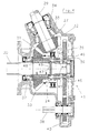
- FIGs 3 and 4 is a sectional view of the Transfer case 27 illustrated in more detail.
- the transfer case 27 essentially from an input shaft 29 and an output shaft 30, on which a bevel gear pair 31 forming bevel gears 32,33 are arranged.
- the output shaft 30 the transfer case 27 is, for example, via a Cardan shaft with a drive shaft of the conveyor and Cutting rotor 11 (Fig.1 and 2) connectable.
- the one-way clutch 24 as a connecting and fastening element form, which is between the bevel gear 33 and the output shaft 30 is located.
- Rolling bearing 34,35,36,37 provided for storage of the input shaft 29 and the output shaft 30.
- a redirect the drive of the conveyor and cutting rotor 11 to the receiving device 5 takes place by means of a further output shaft 38, the spur gears 39.40 with the output shaft 30 is connected.
- the one-way clutch 24 can be arranged and be designed as in DE 297 03 621 U1 is disclosed.
- the transfer case 27 has a circuit arrangement 41 assigned, which essentially consists of a sliding sleeve 42 and a shift lever arrangement 43 (see Fig. 5 and 6) is formed.
- the sliding sleeve 42 is a Serration or a similar positive Connection connected to the output shaft 30 and can thereby from the position shown in Fig. 3, in the the freewheeling state of the one-way clutch 24 is not canceled is in a freewheeling state shown in FIG overriding position and transferred back.
- the sliding sleeve 42 Via spring elements 44 and screws passing through them 45 connected to the spur gear 39 via nuts 46 are, the sliding sleeve 42 is resilient in one does not indicate the freewheeling state of the freewheel clutch 24 held canceling position.
- the sliding sleeve 42 has one or more Carrier 47 on with one on a freewheel housing 48 of the overrunning clutch 24 attached teeth 49 can be brought into engagement.
- FIG Figures 5 and 6 One embodiment of the shift lever assembly 43 is shown in FIG Figures 5 and 6 illustrated in more detail. Like from this Figures shows, includes the shift lever assembly essentially a shift lever 50 which with a Switch shaft 51 cooperates with one in one Groove 52 engaging pin 53 is provided. By a Rotary movement of the shift lever 50 about an axis 54 can now a switching process (cancellation the freewheeling state of the one-way clutch 24) be initiated. First, there is the possibility if the drivers 47 match the toothing 49 to perform the switching process directly, whereby a resilient locking pin 55 remains in a position in which a hub 56 of the Shift lever 50 and one connected to the shift shaft 51 Socket 57 are coupled together (Fig.6).
- the Socket 57 of the selector shaft 51 in a position in which the connection between the hub 56 and the socket 57 by the locking pin 55 also automatically again will be produced.
- the one-way clutch 24 can thereby be restored, that when reversing the direction of rotation from the reverse direction R in the working direction D by sliding of back tooth slopes 61.62 against each other the drivers 47 of the sliding sleeve 42 and the Teeth 49 of the freewheel housing 48 automatically except Intervention.
- the shift lever 50 of the shift lever assembly 43 also arrives automatically from the preset position back to the rest position.
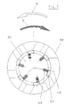
- FIG. 7 shows a possible embodiment of the one-way clutch 24 illustrates in a sectional view.
- Carriers 63 are provided, via which in the working direction D of the freewheel housing 48 a Connection between the output shaft 30 and the freewheel housing 48 is produced.
- the drivers 63 will supported by compression springs 64.
- In the reverse direction R of the freewheel housing 48 however, remains Output shaft 30 and thus the conveyor and cutting rotor 11 stand. Only through the engagement of the driver 47 of the Sliding sleeve 42 (Fig. 3 and 4) in the teeth 49 of Freewheel housing 48 is also in the reverse direction R a positive connection between the freewheel housing 48 and the output shaft 30 created.
- FIG. 65 Another possible exemplary embodiment is shown in FIG a circuit arrangement 65 according to the invention for cancellation of the one-way clutch 24 shown, which consists essentially of a sliding sleeve 66 and a shift lever arrangement 67 for introduction of a switching operation.
- a spring element 68 can be a shift lever 69 of the shift lever arrangement 67 in a preselection position are moved, with a further spring element 70 biased becomes. Due to the effect of this preload are drivers of the sliding sleeve 66 with the freewheel housing 48 engageable.
- Pushbutton 71 is provided, which is connected to the reversing lever 72 the biasing force of the spring element 70 is applied are.
- FIG. 9 illustrates a one according to the invention Reverse rotation of the conveyor and cutting rotor 11 manually or initiated by an auxiliary drive device 73 become. It is provided that the auxiliary drive device 73 so on the pick-up piston press to affix this preferably for the period the turning back of the conveyor and cutting rotor 11 with the flywheel 21 of the collecting piston press in engagement can be brought. According to the invention, the Auxiliary drive device 73 equally as an electric or hydraulically driven device his.
- the postponement of the drive motor 75 is, for example, by a hydraulic Piston-cylinder arrangement 77 reachable.
Landscapes
- Engineering & Computer Science (AREA)
- General Engineering & Computer Science (AREA)
- Mechanical Engineering (AREA)
- Life Sciences & Earth Sciences (AREA)
- Environmental Sciences (AREA)
- Mechanical Operated Clutches (AREA)
- Hydraulic Clutches, Magnetic Clutches, Fluid Clutches, And Fluid Joints (AREA)
- Transmission Devices (AREA)
- Apparatuses For Bulk Treatment Of Fruits And Vegetables And Apparatuses For Preparing Feeds (AREA)
Claims (15)
- Presse à balles comportant une installation de réception (5) pour recevoir des produits de récolte, agricoles, comprenant :caractérisée en ce queune transmission principale et un entraínement à manivelle (23) dérivant de celle-ci pour entraíner un piston (18) effectuant un mouvement de va et vient dans un canal de presse (17) ; etune ligne de transmission dérivant de la transmission principale (22) pour entraíner en commun une installation de transfert (14) pour remplir et vider un canal d'alimentation (15), en amont du canal de presse (17) et un rotor de transfert et de coupe (11) avec ou sans installation de réception (5), en aval dans la ligne d'entraínement ou pour l'entraínement seul d'un rotor de transfert et de coupe (11) avec ou sans installation de réception (5) en aval, dans le sens de l'entraínement ; etun embrayage à roue libre (24) interdisant tout mouvement de rotation dirigé dans le sens opposé du sens de rotation de travail prévu (D) du rotor de transfert et de coupe (11),
l'état de roue libre de l'embrayage à roue libre (24) prévu dans le sens de l'entraínement entre la transmission principale (22) et le rotor de transfert et de coupe (11), existe toujours pendant le fonctionnement normal de la presse, et ne peut être neutralisé que pour induire de manière précise un mouvement de rotation inverse du rotor de transfert et de coupe (11) pour éliminer une perturbation, par action manuelle à l'aide d'un dispositif de commutation (41, 65) et après élimination de la perturbation cet état se rétablit de nouveau par une inversion de sens de rotation (D) de la ligne d'entraínement passant en mode normal pour la presse. - Presse à balles selon la revendication 1,
caractérisée en ce que
l'opération de commutation du dispositif de commutation (41, 65) pour éliminer l'état de roue libre de l'embrayage (24) est présélectionnable. - Presse à balles selon la revendication 1 ou 2,
caractérisée en ce que
le dispositif de commutation (41, 65) pour éliminer l'état de roue libre de l'embrayage (24) comporte un manchon coulissant (42, 66) qui peut être mis en prise avec un boítier de roue libre (48) de l'embrayage (24) pour neutraliser l'état de roue libre. - Presse à balles selon l'une des revendications 1 à 3,
caractérisée en ce que
le dispositif de commutation (41, 65) comporte un dispositif à levier de commutation (43, 67) pour neutraliser l'état de roue libre de l'embrayage (24) qui présélectionne l'établissement d'une liaison par la forme entre le manchon coulissant (42, 66) et le boítier de roue libre (48). - Presse à balles selon la revendication 4,
caractérisée en ce qu'
un levier de commutation (50, 69) du dispositif à levier de commutation (43, 67) peut être mis dans une position présélectionnée et y être bloqué. - Presse à balles selon la revendication 5,
caractérisée en ce que
le levier de commutation (50, 69) du dispositif à levier de commutation (43, 67) peut être bloqué dans la position présélectionnée par des éléments d'encliquetage souples, élastiques. - Presse à balles selon l'une des revendications 1 à 6,
caractérisée en ce que
des organes d'entraínement (47) du manchon coulissant (42, 66) peuvent être mis en prise sous l'action d'une force de précontrainte appliquée par des éléments de ressort (60, 70), automatiquement avec une denture (49) du boítier de roue libre (48) si le levier de commutation (50, 69) du dispositif à levier de commutation (43, 67) se trouve en position de présélection. - Presse à balles selon l'une des revendications 1 à 7,
caractérisée en ce que
le mouvement de rotation inverse du rotor de transfert et de coupe (11) peut être lancé manuellement par un volant d'inertie (21) en amont de la transmission principale (22). - Presse à balles selon l'une des revendications 1 à 8,
caractérisée en ce qu'
elle comprend un dispositif d'entraínement auxiliaire (73) pour lancer le mouvement de rotation inverse du rotor de transfert et de coupe (11). - Presse à balles selon l'une des revendications 1 à 9,
caractérisée en ce qu'
elle comporte une installation d'entraínement auxiliaire (73) pour lancer le mouvement de rotation inverse du rotor de transfert et de coupe (11) sur le volant d'inertie (21). - Presse à balles selon la revendication 10,
caractérisée en ce que
pour lancer le mouvement de rotation inverse, l'installation d'entraínement auxiliaire (73) ne se met en prise avec le volant d'inertie (21) que pour la durée de rotation inverse du rotor de transfert et de coupe (11). - Presse à balles selon l'une des revendications 1 à 11,
caractérisée en ce que
le dispositif à levier de commutation (43, 67) est réalisé pour permettre un rétablissement automatique de l'état de roue libre de l'embrayage (24). - Presse à balles selon l'une des revendications 1 à 12,
caractérisée en ce que
le rétablissement automatique de l'état de roue libre de l'embrayage (24) est induit par une inversion de sens de rotation à partir du sens de rotation inverse (R) vers le sens de rotation de travail (D). - Presse à balles selon l'une des revendications 3 à 13,
caractérisée en ce que
le rétablissement automatique de l'état de roue libre est réalisé en faisant glisser des rampes de dents arrières de la denture (49) et des organes d'entraínement (47) du manchon coulissant (42, 66) les unes sur les autres. - Presse à balles selon l'une des revendications 3 à 14,
caractérisée ce qu'
elle comprend des éléments de ressort pour soutenir l'opération de séparation du manchon coulissant (42, 66) par rapport au boítier de roue libre (48) pour rétablir l'état de roue libre de l'embrayage (24).
Applications Claiming Priority (2)
| Application Number | Priority Date | Filing Date | Title |
|---|---|---|---|
| DE19803835A DE19803835C2 (de) | 1998-01-31 | 1998-01-31 | Aufsammelkolbenpresse |
| DE19803835 | 1998-01-31 |
Publications (3)
| Publication Number | Publication Date |
|---|---|
| EP0933018A2 EP0933018A2 (fr) | 1999-08-04 |
| EP0933018A3 EP0933018A3 (fr) | 2001-04-18 |
| EP0933018B1 true EP0933018B1 (fr) | 2002-11-27 |
Family
ID=7856283
Family Applications (1)
| Application Number | Title | Priority Date | Filing Date |
|---|---|---|---|
| EP99100906A Expired - Lifetime EP0933018B1 (fr) | 1998-01-31 | 1999-01-20 | Ramasseuse-presse à piston |
Country Status (2)
| Country | Link |
|---|---|
| EP (1) | EP0933018B1 (fr) |
| DE (2) | DE19803835C2 (fr) |
Families Citing this family (6)
| Publication number | Priority date | Publication date | Assignee | Title |
|---|---|---|---|---|
| DE20005965U1 (de) * | 2000-03-31 | 2000-08-10 | Kverneland Gottmadingen GmbH & Co. KG, 78244 Gottmadingen | Schneidwerk |
| DE102007015649B4 (de) * | 2007-03-31 | 2009-10-29 | Maschinenfabrik Bernard Krone Gmbh | Großballenpresse |
| BE1021131B1 (nl) * | 2013-02-20 | 2016-01-05 | Cnh Industrial Belgium Nv | Balenpers met opstartcontrolesysteem |
| NL2018436B1 (en) * | 2017-02-28 | 2018-09-19 | Lely Patent Nv | Bale forming apparatus and method with a free-wheel clutch |
| US10701866B2 (en) * | 2017-10-25 | 2020-07-07 | Deere & Company | Drive system for intermittent rotation output |
| DE202024102596U1 (de) | 2024-05-21 | 2024-07-01 | Kuhn-Geldrop B.V. | Landwirtschaftliche Ballenpresse |
Family Cites Families (7)
| Publication number | Priority date | Publication date | Assignee | Title |
|---|---|---|---|---|
| AT377675B (de) * | 1978-08-10 | 1985-04-25 | Poettinger Ohg Alois | Foerdervorrichtung fuer einen landwirtschaftlichen ladewagen |
| WO1994024845A2 (fr) * | 1993-05-05 | 1994-11-10 | Same S.P.A. | Machine agricole, notamment presse automotrice a faire des balles de grande dimension |
| DE29504531U1 (de) * | 1995-03-16 | 1995-06-08 | Claas OHG beschränkt haftende offene Handelsgesellschaft, 33428 Harsewinkel | Kolbensammelpresse für landwirtschaftliches Erntegut |
| DE29514322U1 (de) * | 1995-09-07 | 1996-10-10 | Welger GmbH, 38304 Wolfenbüttel | Aufsammelpresse für landwirtschaftliches Erntegut |
| DE19534138C1 (de) * | 1995-09-14 | 1996-10-31 | Claas Ohg | Ballenpresse für Erntegut |
| DE19627397A1 (de) * | 1996-07-06 | 1997-10-02 | Krone Bernhard Gmbh Maschf | Ballenpresse |
| DE29703621U1 (de) * | 1997-02-28 | 1998-04-02 | Maschinenfabriken Bernard Krone Gmbh, 48480 Spelle | Aufsammelkolbenpresse |
-
1998
- 1998-01-31 DE DE19803835A patent/DE19803835C2/de not_active Expired - Fee Related
-
1999
- 1999-01-20 EP EP99100906A patent/EP0933018B1/fr not_active Expired - Lifetime
- 1999-01-20 DE DE59903501T patent/DE59903501D1/de not_active Expired - Fee Related
Also Published As
| Publication number | Publication date |
|---|---|
| DE59903501D1 (de) | 2003-01-09 |
| DE19803835A1 (de) | 1999-08-12 |
| DE19803835C2 (de) | 2002-06-20 |
| EP0933018A3 (fr) | 2001-04-18 |
| EP0933018A2 (fr) | 1999-08-04 |
Similar Documents
| Publication | Publication Date | Title |
|---|---|---|
| EP0855134A1 (fr) | Presse à balles rondes pour produits agricoles | |
| EP2979535A2 (fr) | Dispositif de coupe pour moissonneuses agricoles | |
| DE1816910A1 (de) | Antrieb fuer Futter-Erntemaschinen (Feldhaecksler) | |
| DE19854562A1 (de) | Einrichtung zur Überwachung der Einzugsbaugruppe einer landwirtschaftlichen Erntemaschine | |
| DE2946098A1 (de) | Erntemaschine | |
| DE102021123867A1 (de) | Getriebeanordnung zum Antreiben eines Presskolbens einer Quaderballenpresse | |
| DE60219375T2 (de) | Presse mit einer Reversiereinrichtung für den Rotor | |
| EP3479674A1 (fr) | Moissonneuse agricole | |
| EP0771522B1 (fr) | Presse à balles | |
| DE19534138C1 (de) | Ballenpresse für Erntegut | |
| EP0933018B1 (fr) | Ramasseuse-presse à piston | |
| EP0819375B1 (fr) | Système d'entraínement pour presse à balles | |
| EP1864567B1 (fr) | Ramasseur | |
| DE19538370C1 (de) | Antrieb für eine Kolbensammelpresse für landwirtschaftliche Erntegüter | |
| DE69009977T2 (de) | Abscherbolzenverbindung. | |
| EP4233523B1 (fr) | Presse à balles agricole et son procédé de fonctionnement | |
| DE4216483C2 (de) | Rechenförderer mit Überlastsicherung innerhalb einer Aufsammelkolbenpresse für landwirtschaftliches Erntegut | |
| DE19627397A1 (de) | Ballenpresse | |
| DE10021660C2 (de) | Erntemaschine, insbesondere selbstfahrender Feldhäcksler | |
| DE9211256U1 (de) | Aufsammelkolbenpresse für landwirtschaftliches Erntegut | |
| DE29912884U1 (de) | Erntefahrzeug, insbesondere Aufsammelballenpresse | |
| DE102019006252B4 (de) | Antriebsanordnung für eine Rundballenpresse und Rundballenpresse mit der Antriebsanordnung | |
| DE29703621U1 (de) | Aufsammelkolbenpresse | |
| DE9312141U1 (de) | Aufsammelpresse für landwirtschaftliche Halmgüter | |
| EP4466976B1 (fr) | Unité de transmission |
Legal Events
| Date | Code | Title | Description |
|---|---|---|---|
| PUAI | Public reference made under article 153(3) epc to a published international application that has entered the european phase |
Free format text: ORIGINAL CODE: 0009012 |
|
| AK | Designated contracting states |
Kind code of ref document: A2 Designated state(s): BE DE FR |
|
| AX | Request for extension of the european patent |
Free format text: AL;LT;LV;MK;RO;SI |
|
| RAP1 | Party data changed (applicant data changed or rights of an application transferred) |
Owner name: MASCHINENFABRIK BERNARD KRONE GMBH |
|
| PUAL | Search report despatched |
Free format text: ORIGINAL CODE: 0009013 |
|
| AK | Designated contracting states |
Kind code of ref document: A3 Designated state(s): AT BE CH CY DE DK ES FI FR GB GR IE IT LI LU MC NL PT SE |
|
| AX | Request for extension of the european patent |
Free format text: AL;LT;LV;MK;RO;SI |
|
| 17P | Request for examination filed |
Effective date: 20011012 |
|
| AKX | Designation fees paid |
Free format text: BE DE FR |
|
| 17Q | First examination report despatched |
Effective date: 20020205 |
|
| GRAG | Despatch of communication of intention to grant |
Free format text: ORIGINAL CODE: EPIDOS AGRA |
|
| GRAG | Despatch of communication of intention to grant |
Free format text: ORIGINAL CODE: EPIDOS AGRA |
|
| GRAH | Despatch of communication of intention to grant a patent |
Free format text: ORIGINAL CODE: EPIDOS IGRA |
|
| RBV | Designated contracting states (corrected) |
Designated state(s): BE DE FR |
|
| GRAH | Despatch of communication of intention to grant a patent |
Free format text: ORIGINAL CODE: EPIDOS IGRA |
|
| GRAA | (expected) grant |
Free format text: ORIGINAL CODE: 0009210 |
|
| AK | Designated contracting states |
Kind code of ref document: B1 Designated state(s): BE DE FR |
|
| PG25 | Lapsed in a contracting state [announced via postgrant information from national office to epo] |
Ref country code: FR Free format text: LAPSE BECAUSE OF FAILURE TO SUBMIT A TRANSLATION OF THE DESCRIPTION OR TO PAY THE FEE WITHIN THE PRESCRIBED TIME-LIMIT Effective date: 20021127 |
|
| REF | Corresponds to: |
Ref document number: 59903501 Country of ref document: DE Date of ref document: 20030109 |
|
| PG25 | Lapsed in a contracting state [announced via postgrant information from national office to epo] |
Ref country code: BE Free format text: LAPSE BECAUSE OF NON-PAYMENT OF DUE FEES Effective date: 20030131 |
|
| EN | Fr: translation not filed | ||
| PLBE | No opposition filed within time limit |
Free format text: ORIGINAL CODE: 0009261 |
|
| STAA | Information on the status of an ep patent application or granted ep patent |
Free format text: STATUS: NO OPPOSITION FILED WITHIN TIME LIMIT |
|
| 26N | No opposition filed |
Effective date: 20030828 |
|
| PGFP | Annual fee paid to national office [announced via postgrant information from national office to epo] |
Ref country code: DE Payment date: 20050216 Year of fee payment: 7 |
|
| PG25 | Lapsed in a contracting state [announced via postgrant information from national office to epo] |
Ref country code: DE Free format text: LAPSE BECAUSE OF NON-PAYMENT OF DUE FEES Effective date: 20060801 |