EP4233523B1 - Presse à balles agricole et son procédé de fonctionnement - Google Patents
Presse à balles agricole et son procédé de fonctionnement Download PDFInfo
- Publication number
- EP4233523B1 EP4233523B1 EP22215048.4A EP22215048A EP4233523B1 EP 4233523 B1 EP4233523 B1 EP 4233523B1 EP 22215048 A EP22215048 A EP 22215048A EP 4233523 B1 EP4233523 B1 EP 4233523B1
- Authority
- EP
- European Patent Office
- Prior art keywords
- baler
- clutch
- pickup
- rotation
- rotor drive
- Prior art date
- Legal status (The legal status is an assumption and is not a legal conclusion. Google has not performed a legal analysis and makes no representation as to the accuracy of the status listed.)
- Active
Links
Images


Classifications
-
- A—HUMAN NECESSITIES
- A01—AGRICULTURE; FORESTRY; ANIMAL HUSBANDRY; HUNTING; TRAPPING; FISHING
- A01F—PROCESSING OF HARVESTED PRODUCE; HAY OR STRAW PRESSES; DEVICES FOR STORING AGRICULTURAL OR HORTICULTURAL PRODUCE
- A01F15/00—Baling presses for straw, hay or the like
- A01F15/08—Details
- A01F15/10—Feeding devices for the crop material e.g. precompression devices
Definitions
- the invention relates to an agricultural baler according to claim 1 and a method for operating the same according to claim 13.
- Crops growing in a field are usually harvested at harvest time using appropriate agricultural machinery. Since a whole year's harvest is harvested within a few days or weeks, it is necessary to bring the crops to warehouses, for example, where they can be stored until they are used again. In this context, it is not economical to transport the crops loose, as hay or straw, for example, are very voluminous. The crops are therefore compacted using a baler so that they can be transported and then stored particularly easily.
- Such an agricultural baler for compacting crops into bales includes a pickup for picking up crops from the ground.
- the baler also includes a feed screw downstream of the pickup for further conveying the collected crops.
- the pickup typically has an elongated rotary cylinder with a plurality of receiving tines which extend radially outwards from a circumferential surface of the rotary cylinder, so that when the baler is operating as intended, the receiving tines grasp the crop lying on the ground as part of a rotary drive of the pickup and convey it in the direction of the feed auger.
- a cutting rotor downstream of the feed screw is provided for shredding the harvested crop before it is compacted, as well as a mechanical rotor drive for rotating the cutting rotor.
- the baler also includes a compaction device by means of which the harvested crop can be compacted into a bale.
- various principles can be used for compaction, for example the use of a compaction piston in a square baler or the use of a press belt or press rollers in a round baler.
- blockages or blockages can occur during operation of the baler. These are caused, for example, by too much crop being picked up by the pickup and are particularly likely to occur when the crop is wet. Objects lying on the field that are actually Objects that should not be picked up, such as branches or stones, can disrupt the regular operation of the baler.
- the EP 2 250 876 B1 a method for clearing a blockage in a baler is known.
- the method involves first identifying the blockage in the baler and then activating several blockage removal devices at least substantially simultaneously.
- it is intended to signal to a PTO shaft that it is coming out of the outlet and to reduce an electrical voltage in order to thereby reduce the density of the crop compacted into the bale.
- It is also intended to control various elements of the baler, for example raising a guide plate, lowering a drop floor and raising the pickup in order to finally reverse the movement of a rotor drive. This is intended to clear the blockage in the next step.
- the blockage removal devices are then returned to normal operating positions.
- the EP 1 060 652 B1 a drive for a baler is known.
- a main gearbox is provided, the input shaft of which is driven together with a flywheel by a suitable drive source.
- a drive connection for the filling and emptying device and a further drive connection with an overload clutch for the pickup are provided.
- the baler also includes a cutting rotor. It is intended that the drive connection has a measuring device by means of which a load on the filling and emptying device can be determined, so that the measuring device takes on the function of an overload clutch.
- a switching element is provided in the drive connection of the pickup behind the cutting rotor, which is operatively connected to the measuring device. In this way, in the event of an overload in the drive connection of the filling and emptying device, and emptying device, the drive connection of the pickup must be interrupted and, if the overload case is not reached, the drive connection must be restored or maintained.
- a disadvantage of the above-mentioned prior art is that the pickup and the feed screw in particular are either exclusively driven mechanically or hydraulically.
- a mechanical drive does indeed enable a higher torque, but is not suitable for clearing blockages. This is due, for example, to the fact that a mechanical drive is usually quite sluggish and therefore cannot be stopped easily or quickly and/or reversed, i.e., for example, rotated in an opposite direction.
- a hydraulic drive cannot provide as high a torque as a mechanical drive, but is better suited to clearing blockages. In particular, it is particularly easy to reverse the direction of rotation of the drive.
- the requirements for the pickup and feed screw are different. While the pickup requires a high torque to be able to pick up heavy crops, the feed screw only needs a comparatively low torque. Furthermore, in the event of a blockage, it is necessary to be able to operate the feed screw in the opposite direction to its normal direction of rotation in order to return any crops and thus clear a blockage. In contrast, the pickup does not have to be moved during this process; it is actually advantageous if the pickup is stationary. It is therefore clear that the state of the art does not meet the requirements for the pickup or the feed screw.
- the feed screw cooperates with a hydraulic motor, by means of which the feed screw can be driven in rotation.
- the pickup is meanwhile connected to the rotor drive in such a way that the pickup can be driven in rotation by means of the rotor drive.
- a clutch is connected between the rotor drive and the pickup, which alternates between a coupling state in which the Pickup is coupled to the rotor drive, and a disengaged state in which the pickup is decoupled from the rotor drive.
- the coupling is designed to decouple the pickup from the rotor drive as soon as the baler is transferred to a reversing mode in which the feed screw is driven in rotation in a direction opposite to normal operation of the baler.
- the pickup is typically stationary in reversing mode of the baler, while the feed screw is driven in rotation in the opposite direction to the direction of rotation that it has in normal operation of the baler.
- the baler can be reversed. To do this, the pickup is separated from the rotor drive using the clutch. In this way, the pickup is no longer driven, so that it stands still and does not pick up any more crops from the ground, does not transport them in the direction of the feed screw and thus does not make the existing blockage worse. Since experience has shown that this alone cannot reliably remove the blockage, the crop that is causing the blockage must be removed from the baler. For this purpose, the crop is transported out of the baler in the same way as it was transported in. In this context, the direction of rotation of the feed screw is reversed so that crops are no longer transported into the baler, but out of the baler.
- the hydraulic motor of the feed screw provided according to the invention advantageously enables its direction of rotation to be reversed particularly easily.
- the pickup and the feed screw can be operated independently of one another in different ways, the pickup at least indirectly mechanically, namely through the rotor drive, and the feed screw hydraulically, namely through the hydraulic drive.
- the pickup can provide a particularly high torque due to its mechanical drive in the form of the rotor drive and the feed screw can be switched over particularly easily due to its hydraulic drive, i.e. its direction of rotation can be reversed.
- the baler according to the invention thus combines the advantages of both types of drive (mechanical and hydraulic) and thereby improves the operation of the baler.
- the feed screw In connection with the blockage, the feed screw is operated in the opposite direction to its normal direction of rotation, in which it operates in normal operation of the baler, until the blockage is at least essentially completely removed.
- the baler is in its reversing mode.
- the drive state of the feed screw is changed again, whereby the direction of rotation of the feed screw is changed using the hydraulic motor so that it is operated as intended for normal operation of the baler.
- the pickup is reconnected to the rotor drive using the clutch so that the pickup is rotated in accordance with its regular operation. This restores normal operation of the baler and removes the blockage.
- blockages can be eliminated particularly easily in this way and the baler is therefore particularly comfortable to operate.
- the clutch is hydraulically actuated. This advantageously makes it particularly easy to switch the clutch from the engaged state to the disengaged state or vice versa.
- the pickup can be separated from the rotor drive particularly easily, so that the pickup can advantageously be rotated or shut down particularly easily. This is particularly advantageous because the pickup can be switched on or off at short intervals. In practice, it has been shown that this advantageously allows blockages to be removed particularly reliably.
- the invention is particularly advantageous when a hydraulic system is provided which interacts with the hydraulic motor and/or with the clutch, wherein the pickup can preferably be automatically uncoupled from the rotor drive or automatically coupled to the rotor drive as a result of a change in the drive state of the feed screw.
- the drive state of the feed screw can be changed as a result of a blockage and the resulting transfer of the baler from its normal operation to its reversing operation. This can be done in particular by operating the hydraulic motor of the feed screw, which interacts with the hydraulic system, in the opposite direction.
- This change can automatically, in particular by the action of a control, bring about the change in the clutch and thereby decouple the pickup from the rotor drive.
- the control system controls a control valve that switches a hydraulic pressure provided by the hydraulic system to the clutch, whereupon the clutch is transferred from its engaged state to its disengaged state.
- the hydraulic motor can be operated by means of the hydraulic system. so that the feed screw changes its direction of rotation until the blockage is cleared. This can also be done by switching one or more control valves.
- the clutch can again be transferred from the disengaged state to the engaged state using the hydraulic system, so that the pickup is again coupled to the rotor drive and is rotated as intended. Furthermore, the feed screw can be driven again in its intended direction of rotation using the hydraulic system. The baler is then back in normal operation.
- This has the advantage that the baler can be transferred from normal operation to reversing mode or vice versa particularly easily and without manual intervention, in particular by simply switching control valves that control a hydraulic pressure in the hydraulic system to switch both the feed screw and the clutch.
- Another particularly advantageous embodiment is characterized by a control system by means of which the clutch can be actuated directly or indirectly as a result of the change in the drive state of the feed screw.
- the clutch can be transferred from the engaged state to the disengaged state or vice versa. If, for example, it is determined that the speed of the feed screw is decreasing or its torque is increasing, this can be a sign of a blockage.
- the baler can then be transferred manually by means of a switch or automatically by means of a control system into its reversing mode by changing the drive state of the feed screw and thus operating it in the opposite direction of rotation.
- the clutch is actuated at least indirectly by means of the control system so that it is transferred from its engaged state to its disengaged state and thus shuts down the pickup.
- this can be done, for example, by switching one or more control valves of a hydraulic system.
- the clutch can be re-engaged using the control system, i.e. transferred from the disengaged state to the engaged state.
- the invention is characterized by a sensor device that interacts with the control and is assigned to the hydraulic motor, whereby a change in the operating pressure of the hydraulic fluid of the hydraulic motor can be determined by means of the sensor device.
- An increase in the operating pressure above a predeterminable threshold value which can be determined in tests, for example, can be an indicator that a blockage is present, so that the baler is subsequently switched to its reversing mode by means of the control.
- the clutch when the baler is in normal operation, in which the feed screw is rotationally driven as intended, the clutch is in its engaged state.
- normal operation in normal operation the clutch is engaged so that the pickup is operatively connected to the rotor drive and the pickup is thus driven.
- normal operation is therefore characterized by the fact that the feed screw and the pickup are operated. Because the clutch is engaged in normal operation, a particularly safe and reliable operation of the baler can be achieved.
- the clutch in its disengaged state.
- the pickup is therefore not operatively connected to the rotor drive in the blockage state.
- a switch can be operated by a baler operator, whereby the baler can be put into reversing mode by operating the switch, in which the feed screw is rotated in a direction opposite to normal operation of the baler.
- an operator can determine or assess whether a blockage exists or is imminent.
- the operator can also hear or see whether a blockage exists.
- the operator can assess whether a blockage exists, for example by listening to noticeable noises and visually inspecting the pickup and/or the feed screw.
- the operator can decide whether to initiate reversing mode.
- the invention is particularly advantageous if the clutch has a hydraulic connection for connection to a hydraulic system, wherein the connection is made in such a way that a hydraulic pressure provided by the hydraulic system causes a counterforce to the clamping force, so that when the clutch is subjected to a hydraulic pressure that exceeds the clamping force, the clutch can be transferred into its disengaged state against the tension spring.
- the clutch can thus be brought from the engaged state to the disengaged state or vice versa.
- the clutch interacts with a sensor device, by means of which it can be determined whether the clutch is in its engaged or disengaged state. This provides the operator with information as to whether the clutch is engaged or disengaged and allows him to act accordingly.
- the sensor device can also inform the latter and/or the latter of the state of the clutch.
- the state determined by the sensor device can be transmitted, for example, to the control system, which then controls the hydraulic system and accordingly engages or disengages the clutch.
- This has the advantage that the baler can be operated at least largely automatically. This advantageously enables particularly efficient operation, which is also particularly error-free, since errors caused by human action are particularly limited.
- the invention also relates to a method for operating the aforementioned baler. Advantages and details of the baler apply equally to the method and vice versa.
- the method is particularly advantageous when an operating pressure of the hydraulic fluid of the hydraulic motor is monitored by means of a sensor device, wherein in the event of an increase in the operating pressure, in particular as a result of an unintentional blockage of the feed screw, information is sent to a control system of the baler, which then sends a control command, as a result of which the pickup is decoupled from the rotor drive.
- An increase in the operating pressure of the hydraulic motor can be interpreted as an indicator of a blockage of the feed screw. This is because an increased operating pressure is a sign that the hydraulic motor must provide increased power. Such a case can be caused by a blockage, for example, since the feed screw is loaded with a particularly large amount of crop and rotates with difficulty, in particular slowly and/or unevenly.
- a blockage can therefore be detected particularly reliably using the sensor device.
- This has the advantage that the baler can be operated particularly gently, as blockages are detected at an early stage and can be eliminated by taking appropriate measures (transferring the baler to its Reversing operation (disengaging the pickup and reversing the direction of rotation of the feed screw) can prevent possible damage.
- the method is particularly advantageous when the clutch is operated hydraulically, whereby the clutch is subjected to hydraulic pressure from a hydraulic system to transfer it to its disengaged state and the hydraulic pressure is reduced, preferably gradually, to transfer it to its engaged state.
- the clutch can be opened or closed gradually by applying hydraulic pressure. This is particularly advantageous when engaging the clutch, as the clutch is not suddenly loaded but is gradually closed and thus gradually becomes force-locked. This has the advantage that the clutch can be operated in a particularly gentle manner on the material, which enables the baler to be operated with particularly low wear and therefore particularly cost-effectively.
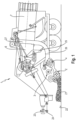
- FIG 1 shows a schematic side view of a baler 1 according to the invention.
- the baler 1 is designed to pick up crop 21 lying on a base 22 and to compact it into crop bales 7.
- the baler 1 is attached as an attachment to an agricultural work machine, for example a tractor, by means of a trailer coupling 23.
- an agricultural work machine for example a tractor
- the tractor is not shown in Figure 1
- the baler is connected to a drive of the tractor by means of an output shaft 24 , so that the baler 1 can be supplied with power by the tractor.
- the baler 1 has a pickup 2.
- the pickup 2 has an elongated rotary cylinder with a plurality of picking tines 29 , which extend from a lateral surface of the rotary cylinder extend radially outwards, so that the receiving tines 29, during normal operation of the baler 1, are guided closely over the ground 22 in the course of a rotary drive of the pickup 2 in such a way that they grasp the crop 21 lying on the ground 22 .
- the crop picked up by the pickup 2 is transported towards a feed screw 3, as for example in Figure 4 can be seen.
- the crop 21 is then fed to a cutting rotor 4 , which chops up the crop 21 so that it can then be better compacted.
- the chopped crop 21 is then fed in portions to a pre-channel 26 by means of a packer 25.
- the crop 21 passes through this pre-channel 26 into a main channel 27, which, in accordance with a final shape of the crop bales 7, has at least essentially a rectangular cross-section and extends in the longitudinal direction of the vehicle. This is particularly good in Figure 1 recognizable.
- the baler 1 also has a compacting element 6, which is a piston.
- the compacting element 6 interacts with the main channel 27 in such a way that the compacting element 6 moves cyclically back and forth in the main channel 27 , grasping and squeezing the crop within the main channel 27 , i.e. compressing it.
- the crop bale 7 is formed at an end of the main channel 27 facing the end of the vehicle .
- the compacting element 6 repeatedly presses the crop 21 to the end of the main channel 27 in the direction of the already compacted crop 21 , so that the crop bale 7 is finally formed.
- a blockage or clogging can occur for a variety of reasons, particularly in an area of the pickup 2 and the feed screw 3. This can be caused, for example, by objects lying around and accidentally picked up, such as stones and/or branches. Crops 21 that are too moist can also lead to a blockage by "sticking" the pickup 2 to a certain extent and thus hindering it.
- the blockage described is particularly good in Figure 5 recognizable.
- the baler 1 is guided in the direction of arrow 13 , with the pickup 2 rotating about a rotation axis 30 in the direction of arrow 35 and the feed screw 3 rotating about a rotation axis 31 in the direction of arrow 34.
- This is in Figure 4 shown and illustrates that the pickup 2 and the feed screw 3 during the rotate in opposite directions during regular operation. This ensures that the crop 21 is transferred particularly well from the pickup to the feed auger 3 .
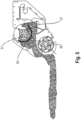
- the functionality of the reversing operation of the baler 1 can be explained by Figure 2 and 3 can be particularly clearly understood.
- the baler 1 has a rotor drive 5 , by means of which the cutting rotor 3 and the pickup 2 can be driven at least indirectly.
- the rotor drive 5 is arranged to the side of the cutting rotor 3 and is connected to it.
- the rotor drive 5 is not directly connected to the pickup 2 , but by means of a coupling 8, which is connected to an output shaft 19 of the rotor drive 5.
- a belt drive 17 is provided, by means of which the pickup 2 is driven.
- This belt drive 17 comprises a pulley 18, which is arranged on the coupling 8 , as can be seen particularly well in Figure 3 can be seen, and a drive belt 28, which engages on one side on the pulley 18 and on the other side is connected to the pickup 2.
- the clutch 8 and the pickup 2 are operatively connected to one another by means of the belt drive 17 .
- the feed screw 3 is driven by means of a hydraulic drive in the form of a hydraulic motor 9 .
- the baler 1 in the example shown also has a hydraulic system 10.
- the hydraulic system 10 comprises a sensor device 16 which is connected to the hydraulic motor 9 and whose hydraulic fluid can determine an operating pressure, for example, and a control valve 20, by means of which the clutch 8 can be switched.
- the sensor device 16 and the control valve 20 are each integrated into the hydraulic system 10 with a hydraulic line 32 .
- the baler 1 comprises a control 11, which is connected to the sensor device 16 and the control valve 20 in a data-transmitting manner, in particular wirelessly.
- the control 11 is connected to a switch 12 , which can be manually operated by a machine operator, whereby he can intervene in the control 11 .
- the clutch 8 also has a measuring wheel 33 and a sensor device 15.
- the sensor device 15 interacts with the measuring wheel 33 in such a way that it can be determined whether the clutch 8 is in its engaged state or its disengaged state.
- the sensor device 15 is also connected to the controller 11 in a data-transmitting, in particular wireless, manner, which is not shown in the figures.
- the sensor device 16 determines an operating pressure of a hydraulic fluid of the hydraulic motor 9 that drives the feed screw 3 and transmits this to the controller 11, which evaluates it.
- the operating pressure increases when the feed screw 3 is blocked, since the hydraulic motor 9 then has to apply more torque to rotate the feed screw 3 despite the blockage.
- this is interpreted by the controller 11 as a blockage.
- the controller 11 initiates the reversing operation of the baler 1 in order to eliminate the blockage.
- the control 11 controls the control valve 20 so that it transfers the clutch 8 from the engaged state to the disengaged state.
- the clutch 8 has a hydraulic connection 14 , as can be seen particularly well in Figure 3 can be seen.
- the clutch 8 is thus transferred to the disengaged state in which it is open, which means that the pickup 2 is no longer driven but comes to a standstill.
- the clutch 8 is subjected to hydraulic pressure, namely by the hydraulic system 10 providing this, passing it via the hydraulic line 32 to the control valve 20 , and from there transmitting it to the clutch 8 via the hydraulic connection 14.
- control 11 controls the hydraulic motor 9 so that it changes its direction of rotation from the normal operation of the baler 1 (compare Figure 4 ) vice versa (compare Figure 5 ).
- the feed screw 3 does not transport the crop 21 responsible for the blockage further into the baler 1 , but transports it out of the baler 1.
- the pickup 2 is shut down, since the crop 21 is not picked up again directly.
Landscapes
- Life Sciences & Earth Sciences (AREA)
- Environmental Sciences (AREA)
- Harvester Elements (AREA)
Claims (15)
- Presse à balles (1) agricole destinée au compactage de produits récoltés pour obtenir des balles de récolte, comprenant- un ramasseur (2) pour ramasser la récolte sur un terrain,- une vis d'amenée (3) placée à la suite du ramasseur (2) et destinée à poursuivre le transport de la récolte ramassée,- un rotor de coupe (4) placé à la suite de la vis d'amenée (3) et destiné à découper la récolte ramassée, avant le compactage de celle-ci,- un entraînement de rotor (5) mécanique pour l'entraînement en rotation du rotor de coupe (4), ainsi que- un organe de compactage (6) au moyen duquel la récolte peut être compactée pour obtenir une balle de récolte (7)le ramasseur (2) coopérant avec l'entraînement de rotor (5) de manière à ce que le ramasseur (2) puisse être entraîné en rotation au moyen de l'entraînement de rotor (5),un accouplement (8) étant intercalé entre l'entraînement de rotor (5) et le ramasseur (2), qui peut être modifié en alternance entre un état d'accouplement, dans lequel le ramasseur (2) est accouplé à l'entraînement de rotor (5), et un état de désaccouplement dans lequel le ramasseur (2) est séparé de l'entraînement de rotor (5),caractérisée en ce quela vis d'amenée (3) coopère avec un moteur hydraulique (9) à l'aide duquel la vis d'amenée (3) peut être entraînée en rotation,l'accouplement (8) étant agencé pour désaccoupler le ramasseur (2) de l'entraînement de rotor (5) dès que la presse à balles (1) est amenée en mode inversé dans lequel la vis d'amenée (3) est entraînée en rotation dans un sens de rotation qui est opposé à celui d'un service normal de la presse à balles (1).
- Presse à balles (1) selon la revendication 1, caractérisée en ce que l'accouplement (8) peut être actionné par voie hydraulique.
- Presse à balles (1) selon la revendication 2, caractérisée par un système hydraulique (10) qui coopère avec le moteur hydraulique (9) et/ou avec l'accouplement (8), le ramasseur (2) pouvant être désaccouplé automatiquement de l'entraînement de rotor (5) ou accouplé automatiquement à l'entraînement de rotor (5), suite à une modification d'un état d'entraînement de la vis d'amenée (3).
- Presse à balles (1) selon une des revendications précédentes, caractérisée par une commande (11) au moyen de laquelle l'accouplement (8) peut être actionné de façon indirecte ou directe, suite à la modification de l'état d'entraînement de la vis d'amenée (3).
- Presse à balles (1) selon la revendication 4, caractérisée par un dispositif capteur (16) qui coopère avec la commande (11) et est associé au moteur hydraulique (9), le dispositif capteur (16) permettant de constater une modification d'une pression de fonctionnement d'un fluide hydraulique du moteur hydraulique (9).
- Presse à balles (1) selon une des revendications précédentes, caractérisée en ce que, lorsque la presse à balles (1) est en service normal, dans lequel la vis d'amenée (3) est entraînée en rotation conformément à l'utilisation prévue, l'accouplement (8) est à l'état d'accouplement, et/ou lorsque la presse à balles (1) est en mode inversé, dans lequel la vis d'amenée (3) est entraînée dans un sens de rotation qui est opposé à celui du service normal, l'accouplement (8) est dans son état de désaccouplement.
- Presse à balles (1) selon une des revendications précédentes, caractérisée en ce que, dans un état de blocage de la vis d'amenée (3), dans lequel la vis d'amenée (3) est bloquée par des produits récoltés, l'accouplement (8) est dans son état de désaccouplement.
- Presse à balles (1) selon une des revendications précédentes, caractérisée par un commutateur (12) qui peut être actionné par un opérateur de la presse à balles (1), la presse à balles (1) pouvant être amenée, par actionnement du commutateur (12), dans un mode inversé dans lequel la vis d'amenée (3) est entraînée dans un sens de rotation qui est opposé à celui d'un service normal de la presse à balles (1).
- Presse à balles (1) selon une des revendications précédentes, caractérisée en ce que l'accouplement (8) comprend un ressort de rappel dont la force de rappel permet de maintenir l'accouplement (8) dans son état d'accouplement, lors d'un service normal de la presse à balles (1).
- Presse à balles (1) selon la revendication 9, caractérisée en ce que l'accouplement (8) présente un raccord hydraulique (14) destiné au raccordement à un système hydraulique (10), le raccordement étant réalisé de manière à ce qu'une pression hydraulique fournie par le système hydraulique (10) engendre une force antagoniste s'opposant à la force de rappel, de sorte qu'en cas de sollicitation de l'accouplement (8) avec une pression hydraulique dépassant la force de rappel, l'accouplement peut être amené dans son état de désaccouplement, à l'encontre du ressort de rappel.
- Presse à balles (1) selon la revendication 4 et 10, caractérisée en ce que la commande (11) est en liaison fonctionnelle avec une vanne de commande (20) au moyen de laquelle une pression hydraulique du système hydraulique (10) peut être appliquée à l'accouplement (8).
- Presse à balles (1) selon une des revendications précédentes, caractérisée en ce que l'accouplement (8) coopère avec un dispositif capteur (15) qui permet de déterminer si l'accouplement (8) se trouve dans son état d'accouplement ou dans son état de désaccouplement.
- Procédé de fonctionnement d'une presse à balles (1) agricole, la presse à balles (1) comprenant- un ramasseur (2) pour ramasser la récolte sur un terrain,- une vis d'amenée (3) placée à la suite du ramasseur (2) et destinée à poursuivre le transport de la récolte ramassée,- un rotor de coupe (4) placé à la suite de la vis d'amenée (3) et destiné à découper la récolte ramassée, avant le compactage de celle-ci,- un entraînement de rotor (5) pour l'entraînement en rotation du rotor de coupe (4), ainsi que- un organe de compactage (6) au moyen duquel la récolte peut être compactée pour obtenir une balle de récolte (7)le ramasseur (2) coopérant avec l'entraînement de rotor (5) de manière à ce que le ramasseur (2) puisse être entraîné en rotation au moyen de l'entraînement de rotor (5),un accouplement (8) étant intercalé entre l'entraînement de rotor (5) et le ramasseur (2), qui peut être modifié en alternance entre un état d'accouplement, dans lequel le ramasseur (2) est accouplé à l'entraînement de rotor (5), et un état de désaccouplement dans lequel le ramasseur (2) est séparé de l'entraînement de rotor (5),caractérisé en ce quela vis d'amenée (3) coopère avec un moteur hydraulique (9) à l'aide duquel la vis d'amenée (3) peut être entraînée en rotation,l'accouplement (8) étant agencé pour désaccoupler le ramasseur (2) de l'entraînement de rotor (5) dès que la presse à balles (1) est amenée en mode inversé dans lequel la vis d'amenée (3) est entraînée en rotation dans un sens de rotation qui est opposé à celui d'un service normal de la presse à balles (1).
sachant queen service normal de la presse à balles (1), l'accouplement (8) est à l'état d'accouplement,sachant que suite à un blocage non intentionnel de la vis d'amenée (3) et/ou dans le cadre de l'amenée de la presse à balles (1) à son mode inversé, l'accouplement (8) est amené automatiquement dans son état de désaccouplement, de sorte que le ramasseur (2) est désaccouplé de l'entraînement de rotor (5). - Procédé la revendication 13, caractérisé en ce qu'une pression de fonctionnement du moteur hydraulique (9) est surveillée au moyen d'un dispositif capteur (16), sachant qu'en cas d'augmentation de la pression de fonctionnement, notamment suite à un blocage non intentionnel de la vis d'amenée (3), une information est envoyée à une commande (11) de la presse à balles (1), qui émet alors une instruction de commande, à la suite de laquelle le ramasseur (2) est désaccouplé de l'entraînement de rotor (5).
- Procédé selon une des revendications précédentes, caractérisé en ce que l'accouplement (8) est actionné par voie hydraulique, sachant que l'accouplement (8) est soumis à une pression hydraulique d'un système hydraulique (10) aux fins d'être amené dans son état de désaccouplement, et la pression hydraulique est diminuée pour l'amener dans son état d'accouplement, de préférence de manière progressive.
Applications Claiming Priority (1)
| Application Number | Priority Date | Filing Date | Title |
|---|---|---|---|
| DE102022102975.1A DE102022102975A1 (de) | 2022-02-09 | 2022-02-09 | Landwirtschaftliche Ballenpresse sowie Verfahren zu deren Betrieb |
Publications (2)
| Publication Number | Publication Date |
|---|---|
| EP4233523A1 EP4233523A1 (fr) | 2023-08-30 |
| EP4233523B1 true EP4233523B1 (fr) | 2024-11-27 |
Family
ID=84547182
Family Applications (1)
| Application Number | Title | Priority Date | Filing Date |
|---|---|---|---|
| EP22215048.4A Active EP4233523B1 (fr) | 2022-02-09 | 2022-12-20 | Presse à balles agricole et son procédé de fonctionnement |
Country Status (2)
| Country | Link |
|---|---|
| EP (1) | EP4233523B1 (fr) |
| DE (1) | DE102022102975A1 (fr) |
Families Citing this family (1)
| Publication number | Priority date | Publication date | Assignee | Title |
|---|---|---|---|---|
| DE202024102596U1 (de) | 2024-05-21 | 2024-07-01 | Kuhn-Geldrop B.V. | Landwirtschaftliche Ballenpresse |
Family Cites Families (4)
| Publication number | Priority date | Publication date | Assignee | Title |
|---|---|---|---|---|
| DE19926827C2 (de) | 1999-06-12 | 2002-07-11 | Case Harvesting Sys Gmbh | Antrieb für eine Kolbensammelpresse für landwirtschaftliche Erntegüter |
| DE10151572A1 (de) * | 2001-10-23 | 2003-10-16 | Claas Selbstfahr Erntemasch | Ballenpresse für landwirtschaftliches Erntegut |
| US8206205B2 (en) | 2009-05-12 | 2012-06-26 | Deere & Company | Method of unplugging control for a feeding system |
| JP7403947B2 (ja) * | 2018-09-20 | 2023-12-25 | 株式会社Ihiアグリテック | ロールベーラ |
-
2022
- 2022-02-09 DE DE102022102975.1A patent/DE102022102975A1/de active Pending
- 2022-12-20 EP EP22215048.4A patent/EP4233523B1/fr active Active
Also Published As
| Publication number | Publication date |
|---|---|
| EP4233523A1 (fr) | 2023-08-30 |
| DE102022102975A1 (de) | 2023-08-10 |
Similar Documents
| Publication | Publication Date | Title |
|---|---|---|
| DE69529428T2 (de) | Umkehreinrichtung für landwirtschaftliche Erntemaschinen | |
| EP0102530B1 (fr) | Méthode pour enlever les surcharges dûes aux amassements de récolte lors de l'enroulement de balles rondes | |
| EP1101398B1 (fr) | Dispositif d'arrêt pour l'arrangement de transport de produit de récolte | |
| DE102008041075A1 (de) | Antriebsanordnung und Verfahren zum Antrieb eines landwirtschaftlichen Arbeitsgeräts | |
| EP0855134A1 (fr) | Presse à balles rondes pour produits agricoles | |
| EP2979535A2 (fr) | Dispositif de coupe pour moissonneuses agricoles | |
| DE102006036199A1 (de) | Förderzusammenbau und Presse | |
| EP3479674B1 (fr) | Moissonneuse agricole | |
| DE29702902U1 (de) | Maschine zum reihenunabhängigen Mähen von Mais u.dgl. stengelartigem Erntegut | |
| EP4233523B1 (fr) | Presse à balles agricole et son procédé de fonctionnement | |
| DE60219375T2 (de) | Presse mit einer Reversiereinrichtung für den Rotor | |
| DE68907517T2 (de) | Ballenpresse. | |
| EP1066745B1 (fr) | Méthode et dispositif de commande pour les organes de travail et transport des machines récolteuses agricoles | |
| EP2179642B1 (fr) | Moissonneuse agricole | |
| DE202011001967U1 (de) | Landwirtschaftliche Maschine | |
| EP0933018B1 (fr) | Ramasseuse-presse à piston | |
| EP4385311B1 (fr) | Agencement d'engrenage pour une presse à balles carrées | |
| EP3959961B1 (fr) | Presse pour produits de récolte à tiges pourvu de module de coupe amovible et procédé de manipulation d'un tel module de coupe amovible | |
| AT402250B (de) | Verfahren zum aufnehmen von halm- und blattgut und zum fördern und beladen eines selbstladewagens | |
| EP3656203A1 (fr) | Maschine agricole de récolte | |
| BE1027694B1 (de) | Antriebsanordnung für ein landwirtschaftliches Arbeitsgerät mit mechanischer Überlastkupplung und selbsttätiger Anpassung des Abschaltmoments | |
| EP1454521A1 (fr) | Dispositif pour envelopper des balles et presse à balles | |
| DE102013107757B4 (de) | Verfahren zum Betreiben eines landwirtschaftlichen Ladewagens und Steuerungseinrichtung | |
| DE4232989A1 (de) | Aufsammelkolbenpresse für landwirtschaftliches Erntegut | |
| EP4466976B1 (fr) | Unité de transmission |
Legal Events
| Date | Code | Title | Description |
|---|---|---|---|
| PUAI | Public reference made under article 153(3) epc to a published international application that has entered the european phase |
Free format text: ORIGINAL CODE: 0009012 |
|
| STAA | Information on the status of an ep patent application or granted ep patent |
Free format text: STATUS: THE APPLICATION HAS BEEN PUBLISHED |
|
| AK | Designated contracting states |
Kind code of ref document: A1 Designated state(s): AL AT BE BG CH CY CZ DE DK EE ES FI FR GB GR HR HU IE IS IT LI LT LU LV MC ME MK MT NL NO PL PT RO RS SE SI SK SM TR |
|
| P01 | Opt-out of the competence of the unified patent court (upc) registered |
Effective date: 20230830 |
|
| STAA | Information on the status of an ep patent application or granted ep patent |
Free format text: STATUS: REQUEST FOR EXAMINATION WAS MADE |
|
| 17P | Request for examination filed |
Effective date: 20240229 |
|
| RBV | Designated contracting states (corrected) |
Designated state(s): AL AT BE BG CH CY CZ DE DK EE ES FI FR GB GR HR HU IE IS IT LI LT LU LV MC ME MK MT NL NO PL PT RO RS SE SI SK SM TR |
|
| GRAP | Despatch of communication of intention to grant a patent |
Free format text: ORIGINAL CODE: EPIDOSNIGR1 |
|
| STAA | Information on the status of an ep patent application or granted ep patent |
Free format text: STATUS: GRANT OF PATENT IS INTENDED |
|
| RIC1 | Information provided on ipc code assigned before grant |
Ipc: A01F 15/10 20060101AFI20240619BHEP |
|
| INTG | Intention to grant announced |
Effective date: 20240704 |
|
| GRAS | Grant fee paid |
Free format text: ORIGINAL CODE: EPIDOSNIGR3 |
|
| GRAA | (expected) grant |
Free format text: ORIGINAL CODE: 0009210 |
|
| STAA | Information on the status of an ep patent application or granted ep patent |
Free format text: STATUS: THE PATENT HAS BEEN GRANTED |
|
| AK | Designated contracting states |
Kind code of ref document: B1 Designated state(s): AL AT BE BG CH CY CZ DE DK EE ES FI FR GB GR HR HU IE IS IT LI LT LU LV MC ME MK MT NL NO PL PT RO RS SE SI SK SM TR |
|
| REG | Reference to a national code |
Ref country code: GB Ref legal event code: FG4D Free format text: NOT ENGLISH |
|
| REG | Reference to a national code |
Ref country code: CH Ref legal event code: EP |
|
| REG | Reference to a national code |
Ref country code: DE Ref legal event code: R096 Ref document number: 502022002231 Country of ref document: DE |
|
| REG | Reference to a national code |
Ref country code: IE Ref legal event code: FG4D Free format text: LANGUAGE OF EP DOCUMENT: GERMAN |
|
| REG | Reference to a national code |
Ref country code: LT Ref legal event code: MG9D |
|
| REG | Reference to a national code |
Ref country code: NL Ref legal event code: MP Effective date: 20241127 |
|
| PG25 | Lapsed in a contracting state [announced via postgrant information from national office to epo] |
Ref country code: IS Free format text: LAPSE BECAUSE OF FAILURE TO SUBMIT A TRANSLATION OF THE DESCRIPTION OR TO PAY THE FEE WITHIN THE PRESCRIBED TIME-LIMIT Effective date: 20250327 Ref country code: HR Free format text: LAPSE BECAUSE OF FAILURE TO SUBMIT A TRANSLATION OF THE DESCRIPTION OR TO PAY THE FEE WITHIN THE PRESCRIBED TIME-LIMIT Effective date: 20241127 Ref country code: PT Free format text: LAPSE BECAUSE OF FAILURE TO SUBMIT A TRANSLATION OF THE DESCRIPTION OR TO PAY THE FEE WITHIN THE PRESCRIBED TIME-LIMIT Effective date: 20250327 |
|
| PG25 | Lapsed in a contracting state [announced via postgrant information from national office to epo] |
Ref country code: FI Free format text: LAPSE BECAUSE OF FAILURE TO SUBMIT A TRANSLATION OF THE DESCRIPTION OR TO PAY THE FEE WITHIN THE PRESCRIBED TIME-LIMIT Effective date: 20241127 Ref country code: NL Free format text: LAPSE BECAUSE OF FAILURE TO SUBMIT A TRANSLATION OF THE DESCRIPTION OR TO PAY THE FEE WITHIN THE PRESCRIBED TIME-LIMIT Effective date: 20241127 |
|
| PG25 | Lapsed in a contracting state [announced via postgrant information from national office to epo] |
Ref country code: BG Free format text: LAPSE BECAUSE OF FAILURE TO SUBMIT A TRANSLATION OF THE DESCRIPTION OR TO PAY THE FEE WITHIN THE PRESCRIBED TIME-LIMIT Effective date: 20241127 |
|
| PG25 | Lapsed in a contracting state [announced via postgrant information from national office to epo] |
Ref country code: ES Free format text: LAPSE BECAUSE OF FAILURE TO SUBMIT A TRANSLATION OF THE DESCRIPTION OR TO PAY THE FEE WITHIN THE PRESCRIBED TIME-LIMIT Effective date: 20241127 |
|
| PG25 | Lapsed in a contracting state [announced via postgrant information from national office to epo] |
Ref country code: NO Free format text: LAPSE BECAUSE OF FAILURE TO SUBMIT A TRANSLATION OF THE DESCRIPTION OR TO PAY THE FEE WITHIN THE PRESCRIBED TIME-LIMIT Effective date: 20250227 |
|
| PG25 | Lapsed in a contracting state [announced via postgrant information from national office to epo] |
Ref country code: LV Free format text: LAPSE BECAUSE OF FAILURE TO SUBMIT A TRANSLATION OF THE DESCRIPTION OR TO PAY THE FEE WITHIN THE PRESCRIBED TIME-LIMIT Effective date: 20241127 Ref country code: GR Free format text: LAPSE BECAUSE OF FAILURE TO SUBMIT A TRANSLATION OF THE DESCRIPTION OR TO PAY THE FEE WITHIN THE PRESCRIBED TIME-LIMIT Effective date: 20250228 |
|
| PG25 | Lapsed in a contracting state [announced via postgrant information from national office to epo] |
Ref country code: PL Free format text: LAPSE BECAUSE OF FAILURE TO SUBMIT A TRANSLATION OF THE DESCRIPTION OR TO PAY THE FEE WITHIN THE PRESCRIBED TIME-LIMIT Effective date: 20241127 |
|
| PG25 | Lapsed in a contracting state [announced via postgrant information from national office to epo] |
Ref country code: RS Free format text: LAPSE BECAUSE OF FAILURE TO SUBMIT A TRANSLATION OF THE DESCRIPTION OR TO PAY THE FEE WITHIN THE PRESCRIBED TIME-LIMIT Effective date: 20250227 |
|
| PG25 | Lapsed in a contracting state [announced via postgrant information from national office to epo] |
Ref country code: SM Free format text: LAPSE BECAUSE OF FAILURE TO SUBMIT A TRANSLATION OF THE DESCRIPTION OR TO PAY THE FEE WITHIN THE PRESCRIBED TIME-LIMIT Effective date: 20241127 |
|
| PG25 | Lapsed in a contracting state [announced via postgrant information from national office to epo] |
Ref country code: DK Free format text: LAPSE BECAUSE OF FAILURE TO SUBMIT A TRANSLATION OF THE DESCRIPTION OR TO PAY THE FEE WITHIN THE PRESCRIBED TIME-LIMIT Effective date: 20241127 |
|
| PG25 | Lapsed in a contracting state [announced via postgrant information from national office to epo] |
Ref country code: EE Free format text: LAPSE BECAUSE OF FAILURE TO SUBMIT A TRANSLATION OF THE DESCRIPTION OR TO PAY THE FEE WITHIN THE PRESCRIBED TIME-LIMIT Effective date: 20241127 |
|
| PG25 | Lapsed in a contracting state [announced via postgrant information from national office to epo] |
Ref country code: RO Free format text: LAPSE BECAUSE OF FAILURE TO SUBMIT A TRANSLATION OF THE DESCRIPTION OR TO PAY THE FEE WITHIN THE PRESCRIBED TIME-LIMIT Effective date: 20241127 |
|
| PG25 | Lapsed in a contracting state [announced via postgrant information from national office to epo] |
Ref country code: SK Free format text: LAPSE BECAUSE OF FAILURE TO SUBMIT A TRANSLATION OF THE DESCRIPTION OR TO PAY THE FEE WITHIN THE PRESCRIBED TIME-LIMIT Effective date: 20241127 |
|
| PG25 | Lapsed in a contracting state [announced via postgrant information from national office to epo] |
Ref country code: CZ Free format text: LAPSE BECAUSE OF FAILURE TO SUBMIT A TRANSLATION OF THE DESCRIPTION OR TO PAY THE FEE WITHIN THE PRESCRIBED TIME-LIMIT Effective date: 20241127 |
|
| PG25 | Lapsed in a contracting state [announced via postgrant information from national office to epo] |
Ref country code: IT Free format text: LAPSE BECAUSE OF FAILURE TO SUBMIT A TRANSLATION OF THE DESCRIPTION OR TO PAY THE FEE WITHIN THE PRESCRIBED TIME-LIMIT Effective date: 20241127 |
|
| PG25 | Lapsed in a contracting state [announced via postgrant information from national office to epo] |
Ref country code: LU Free format text: LAPSE BECAUSE OF NON-PAYMENT OF DUE FEES Effective date: 20241220 |
|
| REG | Reference to a national code |
Ref country code: DE Ref legal event code: R097 Ref document number: 502022002231 Country of ref document: DE |
|
| PG25 | Lapsed in a contracting state [announced via postgrant information from national office to epo] |
Ref country code: SE Free format text: LAPSE BECAUSE OF FAILURE TO SUBMIT A TRANSLATION OF THE DESCRIPTION OR TO PAY THE FEE WITHIN THE PRESCRIBED TIME-LIMIT Effective date: 20241127 |
|
| PG25 | Lapsed in a contracting state [announced via postgrant information from national office to epo] |
Ref country code: MC Free format text: LAPSE BECAUSE OF FAILURE TO SUBMIT A TRANSLATION OF THE DESCRIPTION OR TO PAY THE FEE WITHIN THE PRESCRIBED TIME-LIMIT Effective date: 20241127 |
|
| PLBE | No opposition filed within time limit |
Free format text: ORIGINAL CODE: 0009261 |
|
| STAA | Information on the status of an ep patent application or granted ep patent |
Free format text: STATUS: NO OPPOSITION FILED WITHIN TIME LIMIT |
|
| PG25 | Lapsed in a contracting state [announced via postgrant information from national office to epo] |
Ref country code: IE Free format text: LAPSE BECAUSE OF NON-PAYMENT OF DUE FEES Effective date: 20241220 |
|
| 26N | No opposition filed |
Effective date: 20250828 |
|
| PGFP | Annual fee paid to national office [announced via postgrant information from national office to epo] |
Ref country code: DE Payment date: 20251211 Year of fee payment: 4 |
|
| PGFP | Annual fee paid to national office [announced via postgrant information from national office to epo] |
Ref country code: AT Payment date: 20260113 Year of fee payment: 4 |
|
| PGFP | Annual fee paid to national office [announced via postgrant information from national office to epo] |
Ref country code: FR Payment date: 20251229 Year of fee payment: 4 |
|
| PGFP | Annual fee paid to national office [announced via postgrant information from national office to epo] |
Ref country code: BE Payment date: 20251219 Year of fee payment: 4 |