EP0933248A1 - Armature d'appui-tête, notamment pour siège de véhicule automobile - Google Patents
Armature d'appui-tête, notamment pour siège de véhicule automobile Download PDFInfo
- Publication number
- EP0933248A1 EP0933248A1 EP99400173A EP99400173A EP0933248A1 EP 0933248 A1 EP0933248 A1 EP 0933248A1 EP 99400173 A EP99400173 A EP 99400173A EP 99400173 A EP99400173 A EP 99400173A EP 0933248 A1 EP0933248 A1 EP 0933248A1
- Authority
- EP
- European Patent Office
- Prior art keywords
- notch
- spindle
- seat
- headrest
- clamp
- Prior art date
- Legal status (The legal status is an assumption and is not a legal conclusion. Google has not performed a legal analysis and makes no representation as to the accuracy of the status listed.)
- Granted
Links
Images


Classifications
-
- B—PERFORMING OPERATIONS; TRANSPORTING
- B60—VEHICLES IN GENERAL
- B60N—SEATS SPECIALLY ADAPTED FOR VEHICLES; VEHICLE PASSENGER ACCOMMODATION NOT OTHERWISE PROVIDED FOR
- B60N2/00—Seats specially adapted for vehicles; Arrangement or mounting of seats in vehicles
- B60N2/80—Head-rests
- B60N2/806—Head-rests movable or adjustable
- B60N2/809—Head-rests movable or adjustable vertically slidable
- B60N2/812—Head-rests movable or adjustable vertically slidable characterised by their locking devices
- B60N2/818—Head-rests movable or adjustable vertically slidable characterised by their locking devices with stepwise positioning
Definitions
- the present invention relates to a headrest frame, in particular for a motor vehicle seat, and more particularly such a frame of the type comprising at least one spindle engaged in the file of said seat, in particular by means of a socket integral with the structure of this seat.
- Head restraints used in the automotive industry include known manner a support cushion mounted on a frame which has two pins at its lower end. The protruding end of these pins enters the seat back. When these head restraints are adjustable in height, the pins are generally slidably mounted in sockets integral with the seat frame.
- headrest provided with anti-extraction means comprising a U-shaped spring the ends of the branches of which are attached to the socket, the branches of which generally extend downwards in the direction of the spindle axis, and whose central part is arranged to engage in a notch of the spindle when the latter reaches a certain height position.
- the notch of the spindle is such that when the central part of the spring is engaged, it cannot then come out by simply pulling the headrest
- the spindle must be engaged in the seat back in the free space between the latter's support means and his rear exterior trim.
- the means of support include generally in their rear part a network of metal springs and, for various reasons, the notch of the spindle must be turned towards the front of the vehicle, i.e. towards the network of springs.
- the problem is that the position of the spring network is relatively imprecise in the front / rear direction of the vehicle. It depends on the passenger weight, how they are standing on the seat, and accelerations to which the vehicle is subject.
- the present invention aims in particular to overcome these drawbacks.
- the invention relates to a headrest frame, in particular for a motor vehicle seat, of the type comprising at least a pin engaged in the back of said seat, said pin comprising a notch arranged to cooperate with the active part of a mounted spring on the structure of said seat, said active part being arranged to engage in said spindle notch when the latter reaches a certain height position, characterized in that said notch is made in two parts on either side of a plane of symmetry of the spindle substantially parallel to the plane of symmetry of the headrest, said part central spring forming two corresponding projections in the direction of said parts of the notch.
- the notch has a material bridge in its central part, and the central part of the spring forms a central recess in which the material bridge engages when the central part of the spring engages in the notch.
- the spindle has a smooth surface facing the network of springs and can no longer hang on to it.
- these headrest frames have usually a U-shape, with two vertical side pins joined together by a horizontal middle part.
- the problem is to fix by means as simple as possible the support cushion on this middle part, everything by allowing an adjustment of the inclination of this cushion.
- this middle part is cylindrical with circular section, and a friction-mounted clamp is provided to pivot on this middle part, said clamp being provided with fixing means for the support cushion.
- the inclination of the cushion can be adjusted continuously, and no notch system is required.
- the clamp has an orifice in its enclosing part the frame, the latter having a projection engaged in said orifice.
- the headrest cushion is therefore blocked laterally, and its angular travel is limited.
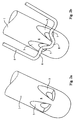
- FIG. 1 a headrest frame made so known in metal tube with circular section.
- This frame is shaped of U with two lateral pins 1 intended to be engaged vertically in the file of a motor vehicle seat, brought together by a party median 2.
- the free end of pins 1 is stamped so as to have a rounded shape.
- each pin has at its end lower two half notches 3 separated by a material bridge 4.
- the half notches 3 are symmetrical with respect to the plane of symmetry of the spindle parallel to the plane of symmetry of the armature.
- Figure 2b also shows a U-shaped locking spring 5.
- spring 5 is mounted in any suitable manner integral with the structure of the seat back, for example fixed by its ends to a socket guide through which the spindle passes.
- the central part 6 of the spring 5 forms two lateral projections 7 in direction of spindle 1, joined by a recess 8 in the direction opposite. So when pin 1 is pulled up and comes into the position shown in Figure 2b relative to the spring 5, the projections 7 engage in the notches 3, blocking any further movement of the pin up. It can be seen that the material bridge 4 engages in the recess 8 when the projections 7 engage in the notches 3.
- the headrest can slide vertically without the notch risks hanging an internal organ on the file of the seat, for example a support spring.
- the middle part 2 of the frame has in its center a projection 9 performed for example by pinching.
- An elastic clamp 10 is frictionally engaged on the middle part 2 of the frame.
- the clamp 10 has an orifice 11 in which the projection 9 when the clamp 10 is mounted on the frame. Projection 9 blocks therefore the clamp 10 laterally and limits its angular movement.
- the clamp 10 finally has holes 12 allowing the mounting of the headrest cushion.
Landscapes
- Engineering & Computer Science (AREA)
- Aviation & Aerospace Engineering (AREA)
- Transportation (AREA)
- Mechanical Engineering (AREA)
- Chair Legs, Seat Parts, And Backrests (AREA)
- Seats For Vehicles (AREA)
- Polyurethanes Or Polyureas (AREA)
- Passenger Equipment (AREA)
- Vehicle Step Arrangements And Article Storage (AREA)
Abstract
Description
- la figure 1 est une vue d'ensemble d'une armature d'appui-tête selon la présente invention;
- les figures 2a et 2b sont des vues de l'extrémité inférieure d'une broche, respectivement sans et avec le ressort de blocage;
- la figure 3 représente la partie supérieure de l'armature sur laquelle est montée la pince de fixation du coussin d'appui; et
- la figure 4 est une vue à plus grande échelle de la zone centrale de cette partie supérieure.
Claims (3)
- Armature d'appui-tête, notamment pour siège de véhicule automobile, du type comprenant au moins une broche (1) engagée dans le dossier dudit siège, ladite broche comportant une encoche (3) agencée pour coopérer avec la partie active (6) d'un ressort monté sur la structure dudit siège, ladite partie active étant agencée pour s'engager dans ladite encoche (3) de la broche lorsque cette dernière atteint une certaine position en hauteur, caractérisé par le fait que ladite encoche (3) est réalisée en deux parties de part et d'autre d'un plan de symétrie de la broche sensiblement parallèle au plan de symétrie de l'appui-tête, ladite partie centrale du ressort formant deux saillies (7) correspondantes en direction desdites parties de l'encoche (3).
- Armature d'appui-tête selon la revendication 1, comprenant deux broches latérales (1) réunies par une partie médiane (2), cette partie médiane étant cylindrique à section circulaire, et une pince (10) étant montée à friction pour pivoter sur cette partie médiane, ladite pince étant munie de moyens de fixation (12) pour le coussin d'appui.
- Armature d'appui-tête selon la revendication 2, dans lequel la pince (10) possède un orifice (11) dans sa partie enserrant l'armature, cette demière possédant une saillie (9) engagée dans ledit orifice.
Applications Claiming Priority (2)
| Application Number | Priority Date | Filing Date | Title |
|---|---|---|---|
| FR9800890A FR2774048B1 (fr) | 1998-01-28 | 1998-01-28 | Armature d'appui-tete, notamment pour siege de vehicule automobile |
| FR9800890 | 1998-01-28 |
Publications (2)
| Publication Number | Publication Date |
|---|---|
| EP0933248A1 true EP0933248A1 (fr) | 1999-08-04 |
| EP0933248B1 EP0933248B1 (fr) | 2004-06-23 |
Family
ID=9522247
Family Applications (1)
| Application Number | Title | Priority Date | Filing Date |
|---|---|---|---|
| EP99400173A Expired - Lifetime EP0933248B1 (fr) | 1998-01-28 | 1999-01-26 | Armature d'appui-tête, notamment pour siège de véhicule automobile |
Country Status (7)
| Country | Link |
|---|---|
| EP (1) | EP0933248B1 (fr) |
| AT (1) | ATE269800T1 (fr) |
| BR (1) | BR9900181A (fr) |
| DE (1) | DE69918198T2 (fr) |
| ES (1) | ES2224563T3 (fr) |
| FR (1) | FR2774048B1 (fr) |
| TR (1) | TR199900188A2 (fr) |
Families Citing this family (1)
| Publication number | Priority date | Publication date | Assignee | Title |
|---|---|---|---|---|
| ES2414580A1 (es) * | 2011-11-24 | 2013-07-19 | Centro Tecnológico De Grupo Copo, S.L.U. | Cabezal abatible lateralmente para asiento de vehículo. |
Citations (6)
| Publication number | Priority date | Publication date | Assignee | Title |
|---|---|---|---|---|
| US3027194A (en) * | 1959-08-03 | 1962-03-27 | Young Spring & Wire Corp | Headrest assembly for vehicle seats |
| US3544162A (en) * | 1967-08-07 | 1970-12-01 | Toyota Motor Co Ltd | Adjustable headrest for vehicle seat |
| GB1322691A (en) * | 1971-03-03 | 1973-07-11 | Universal Oil Prod Co | Seats |
| US4844544A (en) * | 1987-06-30 | 1989-07-04 | Tachi-S Co., Ltd. | Fore-and-aft adjusting device for head rest |
| EP0352881A1 (fr) * | 1988-06-13 | 1990-01-31 | Hoover Universal, Inc. | Appui-tête à coussin pivotable en avant, monté sur une charnière à friction |
| DE4409557A1 (de) * | 1994-03-19 | 1995-09-21 | Itw Ateco Gmbh | Führungshülse für Kopfstützen an Fahrzeugsitzen |
-
1998
- 1998-01-28 FR FR9800890A patent/FR2774048B1/fr not_active Expired - Fee Related
-
1999
- 1999-01-26 ES ES99400173T patent/ES2224563T3/es not_active Expired - Lifetime
- 1999-01-26 AT AT99400173T patent/ATE269800T1/de not_active IP Right Cessation
- 1999-01-26 EP EP99400173A patent/EP0933248B1/fr not_active Expired - Lifetime
- 1999-01-26 DE DE69918198T patent/DE69918198T2/de not_active Expired - Lifetime
- 1999-01-27 BR BR9900181-0A patent/BR9900181A/pt not_active Application Discontinuation
- 1999-01-28 TR TR1999/00188A patent/TR199900188A2/xx unknown
Patent Citations (6)
| Publication number | Priority date | Publication date | Assignee | Title |
|---|---|---|---|---|
| US3027194A (en) * | 1959-08-03 | 1962-03-27 | Young Spring & Wire Corp | Headrest assembly for vehicle seats |
| US3544162A (en) * | 1967-08-07 | 1970-12-01 | Toyota Motor Co Ltd | Adjustable headrest for vehicle seat |
| GB1322691A (en) * | 1971-03-03 | 1973-07-11 | Universal Oil Prod Co | Seats |
| US4844544A (en) * | 1987-06-30 | 1989-07-04 | Tachi-S Co., Ltd. | Fore-and-aft adjusting device for head rest |
| EP0352881A1 (fr) * | 1988-06-13 | 1990-01-31 | Hoover Universal, Inc. | Appui-tête à coussin pivotable en avant, monté sur une charnière à friction |
| DE4409557A1 (de) * | 1994-03-19 | 1995-09-21 | Itw Ateco Gmbh | Führungshülse für Kopfstützen an Fahrzeugsitzen |
Also Published As
| Publication number | Publication date |
|---|---|
| EP0933248B1 (fr) | 2004-06-23 |
| ES2224563T3 (es) | 2005-03-01 |
| DE69918198T2 (de) | 2005-07-21 |
| TR199900188A3 (tr) | 1999-09-21 |
| ATE269800T1 (de) | 2004-07-15 |
| TR199900188A2 (xx) | 1999-09-21 |
| BR9900181A (pt) | 2000-01-18 |
| FR2774048B1 (fr) | 2000-03-10 |
| FR2774048A1 (fr) | 1999-07-30 |
| DE69918198D1 (de) | 2004-07-29 |
Similar Documents
| Publication | Publication Date | Title |
|---|---|---|
| EP0687590B1 (fr) | Système de verrouillage d'un dispositif réglable en translation, tel qu-un appuie-tête | |
| EP1142753B1 (fr) | Appui-tête, notamment pour siège de véhicule automobile | |
| FR2487270A1 (fr) | Dispositif pour le montage d'un appui-tete reglable en hauteur sur un siege d'automobile | |
| FR3036666A1 (fr) | Appui-tete de siege de vehicule et siege comportant un tel appui-tete | |
| FR3075125A1 (fr) | Dispositif de support pour appareil electronique portatif | |
| FR2814994A1 (fr) | Agencement pour la fixation d'un siege d'enfant au siege d'un vehicule | |
| EP0205379A1 (fr) | Boucle, notamment de ceinture de sécurité | |
| EP0909244A1 (fr) | Dispositif de blocage en hauteur d'un appui-tete, notamment pour siege de vehicule automobile | |
| FR2796018A1 (fr) | Appui-tete utilisable par un enfant | |
| EP0516495A1 (fr) | Dipositif de siège pour passager enfant intégré au composant d'un siège principal de véhicule automobile | |
| EP0933248B1 (fr) | Armature d'appui-tête, notamment pour siège de véhicule automobile | |
| EP1514748B1 (fr) | Dispositif de guidage de sangle d'une ceinture de sécurité | |
| EP0296939B1 (fr) | Accoudoir central avant à deux positions stables d'un véhicule automobile | |
| FR2689825A1 (fr) | Appui-tête pour siège de véhicule automobile. | |
| FR2810929A1 (fr) | Dispositif d'assise pour vehicule | |
| FR3016146A1 (fr) | Glissiere et siege de vehicule automobile comportant une telle glissiere | |
| FR2796344A1 (fr) | Mecanisme d'ancrage et d'articulation, notamment pour un siege arriere d'un vehicule automobile | |
| FR2897566A1 (fr) | Assise d'un siege de vehicule automobile comportant une traverse d'anti-sousmarinage. | |
| EP0408415A1 (fr) | Dispositif de siège auto pour enfant et son procédé de fabrication | |
| EP3784522B1 (fr) | Embase de montage a pivotement pour accoudoir de dossier de banquette dotee d'un element metallique d'ancrage anti-basculement | |
| FR2778876A1 (fr) | Dispositif de verrouillage d'un dossier inclinable d'une banquette dans un vehicule | |
| FR2859953A1 (fr) | Siege de vehicule et vehicule comportant un tel siege. | |
| FR2756789A1 (fr) | Dispositif de blocage en hauteur d'un appui-tete, notamment pour siege de vehicule automobile | |
| FR2739813A1 (fr) | Dispositif de maintien de la tete d'un occupant d'un vehicule automobile | |
| FR2750661A1 (fr) | Agencement d'un ensemble de siege dans un habitacle de vehicule automobile |
Legal Events
| Date | Code | Title | Description |
|---|---|---|---|
| PUAI | Public reference made under article 153(3) epc to a published international application that has entered the european phase |
Free format text: ORIGINAL CODE: 0009012 |
|
| AK | Designated contracting states |
Kind code of ref document: A1 Designated state(s): AT BE DE DK ES FI GB IE IT NL PT SE |
|
| AX | Request for extension of the european patent |
Free format text: AL;LT;LV;MK;RO;SI |
|
| 17P | Request for examination filed |
Effective date: 19991221 |
|
| AKX | Designation fees paid |
Free format text: AT BE DE DK ES FI GB IE IT NL PT SE |
|
| 17Q | First examination report despatched |
Effective date: 20030314 |
|
| GRAP | Despatch of communication of intention to grant a patent |
Free format text: ORIGINAL CODE: EPIDOSNIGR1 |
|
| GRAP | Despatch of communication of intention to grant a patent |
Free format text: ORIGINAL CODE: EPIDOSNIGR1 |
|
| GRAS | Grant fee paid |
Free format text: ORIGINAL CODE: EPIDOSNIGR3 |
|
| GRAA | (expected) grant |
Free format text: ORIGINAL CODE: 0009210 |
|
| AK | Designated contracting states |
Kind code of ref document: B1 Designated state(s): AT BE DE DK ES FI GB IE IT NL PT SE |
|
| PG25 | Lapsed in a contracting state [announced via postgrant information from national office to epo] |
Ref country code: NL Free format text: LAPSE BECAUSE OF FAILURE TO SUBMIT A TRANSLATION OF THE DESCRIPTION OR TO PAY THE FEE WITHIN THE PRESCRIBED TIME-LIMIT Effective date: 20040623 Ref country code: IE Free format text: LAPSE BECAUSE OF FAILURE TO SUBMIT A TRANSLATION OF THE DESCRIPTION OR TO PAY THE FEE WITHIN THE PRESCRIBED TIME-LIMIT Effective date: 20040623 Ref country code: FI Free format text: LAPSE BECAUSE OF FAILURE TO SUBMIT A TRANSLATION OF THE DESCRIPTION OR TO PAY THE FEE WITHIN THE PRESCRIBED TIME-LIMIT Effective date: 20040623 Ref country code: AT Free format text: LAPSE BECAUSE OF FAILURE TO SUBMIT A TRANSLATION OF THE DESCRIPTION OR TO PAY THE FEE WITHIN THE PRESCRIBED TIME-LIMIT Effective date: 20040623 |
|
| REG | Reference to a national code |
Ref country code: GB Ref legal event code: FG4D Free format text: NOT ENGLISH |
|
| REG | Reference to a national code |
Ref country code: IE Ref legal event code: FG4D Free format text: FRENCH |
|
| REF | Corresponds to: |
Ref document number: 69918198 Country of ref document: DE Date of ref document: 20040729 Kind code of ref document: P |
|
| PG25 | Lapsed in a contracting state [announced via postgrant information from national office to epo] |
Ref country code: SE Free format text: LAPSE BECAUSE OF FAILURE TO SUBMIT A TRANSLATION OF THE DESCRIPTION OR TO PAY THE FEE WITHIN THE PRESCRIBED TIME-LIMIT Effective date: 20040923 Ref country code: DK Free format text: LAPSE BECAUSE OF FAILURE TO SUBMIT A TRANSLATION OF THE DESCRIPTION OR TO PAY THE FEE WITHIN THE PRESCRIBED TIME-LIMIT Effective date: 20040923 |
|
| GBT | Gb: translation of ep patent filed (gb section 77(6)(a)/1977) |
Effective date: 20040922 |
|
| NLV1 | Nl: lapsed or annulled due to failure to fulfill the requirements of art. 29p and 29m of the patents act | ||
| PGFP | Annual fee paid to national office [announced via postgrant information from national office to epo] |
Ref country code: GB Payment date: 20050126 Year of fee payment: 7 |
|
| PG25 | Lapsed in a contracting state [announced via postgrant information from national office to epo] |
Ref country code: BE Free format text: LAPSE BECAUSE OF NON-PAYMENT OF DUE FEES Effective date: 20050131 |
|
| REG | Reference to a national code |
Ref country code: ES Ref legal event code: FG2A Ref document number: 2224563 Country of ref document: ES Kind code of ref document: T3 |
|
| REG | Reference to a national code |
Ref country code: IE Ref legal event code: FD4D |
|
| PLBE | No opposition filed within time limit |
Free format text: ORIGINAL CODE: 0009261 |
|
| STAA | Information on the status of an ep patent application or granted ep patent |
Free format text: STATUS: NO OPPOSITION FILED WITHIN TIME LIMIT |
|
| 26N | No opposition filed |
Effective date: 20050324 |
|
| BERE | Be: lapsed |
Owner name: CENTRE D'ETUDES ET RECHERCHE POUR L'AUTOMOBILE *CE Effective date: 20050131 |
|
| PG25 | Lapsed in a contracting state [announced via postgrant information from national office to epo] |
Ref country code: GB Free format text: LAPSE BECAUSE OF NON-PAYMENT OF DUE FEES Effective date: 20060126 |
|
| PGFP | Annual fee paid to national office [announced via postgrant information from national office to epo] |
Ref country code: IT Payment date: 20060131 Year of fee payment: 8 |
|
| GBPC | Gb: european patent ceased through non-payment of renewal fee |
Effective date: 20060126 |
|
| BERE | Be: lapsed |
Owner name: CENTRE D'ETUDES ET RECHERCHE POUR L'AUTOMOBILE *CE Effective date: 20050131 |
|
| PG25 | Lapsed in a contracting state [announced via postgrant information from national office to epo] |
Ref country code: PT Free format text: LAPSE BECAUSE OF NON-PAYMENT OF DUE FEES Effective date: 20041123 |
|
| PG25 | Lapsed in a contracting state [announced via postgrant information from national office to epo] |
Ref country code: IT Free format text: LAPSE BECAUSE OF NON-PAYMENT OF DUE FEES Effective date: 20070126 |
|
| PGFP | Annual fee paid to national office [announced via postgrant information from national office to epo] |
Ref country code: ES Payment date: 20100125 Year of fee payment: 12 |
|
| PGFP | Annual fee paid to national office [announced via postgrant information from national office to epo] |
Ref country code: DE Payment date: 20100121 Year of fee payment: 12 |
|
| REG | Reference to a national code |
Ref country code: DE Ref legal event code: R119 Ref document number: 69918198 Country of ref document: DE Effective date: 20110802 |
|
| REG | Reference to a national code |
Ref country code: ES Ref legal event code: FD2A Effective date: 20120220 |
|
| PG25 | Lapsed in a contracting state [announced via postgrant information from national office to epo] |
Ref country code: ES Free format text: LAPSE BECAUSE OF NON-PAYMENT OF DUE FEES Effective date: 20110127 |
|
| PG25 | Lapsed in a contracting state [announced via postgrant information from national office to epo] |
Ref country code: DE Free format text: LAPSE BECAUSE OF NON-PAYMENT OF DUE FEES Effective date: 20110802 |