EP0933445A1 - Procédé et dispositif pour le revêtement de pieces par dépÔt chimique en phase vapeur - Google Patents
Procédé et dispositif pour le revêtement de pieces par dépÔt chimique en phase vapeur Download PDFInfo
- Publication number
- EP0933445A1 EP0933445A1 EP99100905A EP99100905A EP0933445A1 EP 0933445 A1 EP0933445 A1 EP 0933445A1 EP 99100905 A EP99100905 A EP 99100905A EP 99100905 A EP99100905 A EP 99100905A EP 0933445 A1 EP0933445 A1 EP 0933445A1
- Authority
- EP
- European Patent Office
- Prior art keywords
- container
- gas
- coating
- gas phase
- workpieces
- Prior art date
- Legal status (The legal status is an assumption and is not a legal conclusion. Google has not performed a legal analysis and makes no representation as to the accuracy of the status listed.)
- Granted
Links
- 238000000576 coating method Methods 0.000 title claims abstract description 152
- 239000011248 coating agent Substances 0.000 title claims abstract description 121
- 238000000034 method Methods 0.000 title abstract description 11
- 239000012190 activator Substances 0.000 claims abstract description 23
- 239000000126 substance Substances 0.000 claims abstract description 8
- 238000010438 heat treatment Methods 0.000 claims abstract description 5
- 239000007789 gas Substances 0.000 claims description 165
- 239000003380 propellant Substances 0.000 claims description 49
- XKRFYHLGVUSROY-UHFFFAOYSA-N Argon Chemical compound [Ar] XKRFYHLGVUSROY-UHFFFAOYSA-N 0.000 claims description 30
- 239000008187 granular material Substances 0.000 claims description 23
- 229910052786 argon Inorganic materials 0.000 claims description 17
- 239000000463 material Substances 0.000 claims description 15
- VYZAMTAEIAYCRO-UHFFFAOYSA-N Chromium Chemical compound [Cr] VYZAMTAEIAYCRO-UHFFFAOYSA-N 0.000 claims description 13
- 239000000919 ceramic Substances 0.000 claims description 6
- 229910052804 chromium Inorganic materials 0.000 claims description 4
- 239000011651 chromium Substances 0.000 claims description 4
- 238000009826 distribution Methods 0.000 claims description 3
- 238000001704 evaporation Methods 0.000 claims description 2
- 229910052736 halogen Inorganic materials 0.000 claims description 2
- 150000002367 halogens Chemical class 0.000 claims description 2
- 230000004308 accommodation Effects 0.000 abstract 1
- 229910052751 metal Inorganic materials 0.000 description 18
- 239000002184 metal Substances 0.000 description 18
- 229910052782 aluminium Inorganic materials 0.000 description 8
- XAGFODPZIPBFFR-UHFFFAOYSA-N aluminium Chemical compound [Al] XAGFODPZIPBFFR-UHFFFAOYSA-N 0.000 description 7
- 238000010790 dilution Methods 0.000 description 5
- 239000012895 dilution Substances 0.000 description 5
- 238000009792 diffusion process Methods 0.000 description 4
- 229910021555 Chromium Chloride Inorganic materials 0.000 description 3
- 230000015572 biosynthetic process Effects 0.000 description 3
- QSWDMMVNRMROPK-UHFFFAOYSA-K chromium(3+) trichloride Chemical compound [Cl-].[Cl-].[Cl-].[Cr+3] QSWDMMVNRMROPK-UHFFFAOYSA-K 0.000 description 3
- 239000002245 particle Substances 0.000 description 3
- PXHVJJICTQNCMI-UHFFFAOYSA-N Nickel Chemical compound [Ni] PXHVJJICTQNCMI-UHFFFAOYSA-N 0.000 description 2
- 230000002411 adverse Effects 0.000 description 2
- 239000012159 carrier gas Substances 0.000 description 2
- 230000000694 effects Effects 0.000 description 2
- 238000000926 separation method Methods 0.000 description 2
- ZMZGFLUUZLELNE-UHFFFAOYSA-N 2,3,5-triiodobenzoic acid Chemical compound OC(=O)C1=CC(I)=CC(I)=C1I ZMZGFLUUZLELNE-UHFFFAOYSA-N 0.000 description 1
- QCWXUUIWCKQGHC-UHFFFAOYSA-N Zirconium Chemical compound [Zr] QCWXUUIWCKQGHC-UHFFFAOYSA-N 0.000 description 1
- 239000000956 alloy Substances 0.000 description 1
- 229910045601 alloy Inorganic materials 0.000 description 1
- ZCDOYSPFYFSLEW-UHFFFAOYSA-N chromate(2-) Chemical compound [O-][Cr]([O-])(=O)=O ZCDOYSPFYFSLEW-UHFFFAOYSA-N 0.000 description 1
- 238000004532 chromating Methods 0.000 description 1
- 230000006835 compression Effects 0.000 description 1
- 238000007906 compression Methods 0.000 description 1
- 238000010276 construction Methods 0.000 description 1
- 230000007423 decrease Effects 0.000 description 1
- 230000001419 dependent effect Effects 0.000 description 1
- 238000009795 derivation Methods 0.000 description 1
- 230000005484 gravity Effects 0.000 description 1
- 150000002484 inorganic compounds Chemical class 0.000 description 1
- 229910010272 inorganic material Inorganic materials 0.000 description 1
- 238000009434 installation Methods 0.000 description 1
- 239000007788 liquid Substances 0.000 description 1
- 229910052759 nickel Inorganic materials 0.000 description 1
- 239000000843 powder Substances 0.000 description 1
- 238000010926 purge Methods 0.000 description 1
- 230000000630 rising effect Effects 0.000 description 1
- 238000009827 uniform distribution Methods 0.000 description 1
- 229910052726 zirconium Inorganic materials 0.000 description 1
Images



Classifications
-
- C—CHEMISTRY; METALLURGY
- C23—COATING METALLIC MATERIAL; COATING MATERIAL WITH METALLIC MATERIAL; CHEMICAL SURFACE TREATMENT; DIFFUSION TREATMENT OF METALLIC MATERIAL; COATING BY VACUUM EVAPORATION, BY SPUTTERING, BY ION IMPLANTATION OR BY CHEMICAL VAPOUR DEPOSITION, IN GENERAL; INHIBITING CORROSION OF METALLIC MATERIAL OR INCRUSTATION IN GENERAL
- C23C—COATING METALLIC MATERIAL; COATING MATERIAL WITH METALLIC MATERIAL; SURFACE TREATMENT OF METALLIC MATERIAL BY DIFFUSION INTO THE SURFACE, BY CHEMICAL CONVERSION OR SUBSTITUTION; COATING BY VACUUM EVAPORATION, BY SPUTTERING, BY ION IMPLANTATION OR BY CHEMICAL VAPOUR DEPOSITION, IN GENERAL
- C23C16/00—Chemical coating by decomposition of gaseous compounds, without leaving reaction products of surface material in the coating, i.e. chemical vapour deposition [CVD] processes
- C23C16/22—Chemical coating by decomposition of gaseous compounds, without leaving reaction products of surface material in the coating, i.e. chemical vapour deposition [CVD] processes characterised by the deposition of inorganic material, other than metallic material
- C23C16/30—Deposition of compounds, mixtures or solid solutions, e.g. borides, carbides, nitrides
- C23C16/40—Oxides
- C23C16/405—Oxides of refractory metals or yttrium
-
- C—CHEMISTRY; METALLURGY
- C23—COATING METALLIC MATERIAL; COATING MATERIAL WITH METALLIC MATERIAL; CHEMICAL SURFACE TREATMENT; DIFFUSION TREATMENT OF METALLIC MATERIAL; COATING BY VACUUM EVAPORATION, BY SPUTTERING, BY ION IMPLANTATION OR BY CHEMICAL VAPOUR DEPOSITION, IN GENERAL; INHIBITING CORROSION OF METALLIC MATERIAL OR INCRUSTATION IN GENERAL
- C23C—COATING METALLIC MATERIAL; COATING MATERIAL WITH METALLIC MATERIAL; SURFACE TREATMENT OF METALLIC MATERIAL BY DIFFUSION INTO THE SURFACE, BY CHEMICAL CONVERSION OR SUBSTITUTION; COATING BY VACUUM EVAPORATION, BY SPUTTERING, BY ION IMPLANTATION OR BY CHEMICAL VAPOUR DEPOSITION, IN GENERAL
- C23C10/00—Solid state diffusion of only metal elements or silicon into metallic material surfaces
- C23C10/06—Solid state diffusion of only metal elements or silicon into metallic material surfaces using gases
-
- C—CHEMISTRY; METALLURGY
- C23—COATING METALLIC MATERIAL; COATING MATERIAL WITH METALLIC MATERIAL; CHEMICAL SURFACE TREATMENT; DIFFUSION TREATMENT OF METALLIC MATERIAL; COATING BY VACUUM EVAPORATION, BY SPUTTERING, BY ION IMPLANTATION OR BY CHEMICAL VAPOUR DEPOSITION, IN GENERAL; INHIBITING CORROSION OF METALLIC MATERIAL OR INCRUSTATION IN GENERAL
- C23C—COATING METALLIC MATERIAL; COATING MATERIAL WITH METALLIC MATERIAL; SURFACE TREATMENT OF METALLIC MATERIAL BY DIFFUSION INTO THE SURFACE, BY CHEMICAL CONVERSION OR SUBSTITUTION; COATING BY VACUUM EVAPORATION, BY SPUTTERING, BY ION IMPLANTATION OR BY CHEMICAL VAPOUR DEPOSITION, IN GENERAL
- C23C16/00—Chemical coating by decomposition of gaseous compounds, without leaving reaction products of surface material in the coating, i.e. chemical vapour deposition [CVD] processes
- C23C16/44—Chemical coating by decomposition of gaseous compounds, without leaving reaction products of surface material in the coating, i.e. chemical vapour deposition [CVD] processes characterised by the method of coating
- C23C16/455—Chemical coating by decomposition of gaseous compounds, without leaving reaction products of surface material in the coating, i.e. chemical vapour deposition [CVD] processes characterised by the method of coating characterised by the method used for introducing gases into reaction chamber or for modifying gas flows in reaction chamber
- C23C16/45587—Mechanical means for changing the gas flow
- C23C16/45589—Movable means, e.g. fans
Definitions
- the present invention relates to a gas phase coating process in which one or more workpieces to be coated are arranged in a container, the container being heated and a donor a coating gas forms, which comes into contact with the workpiece, and a device for gas phase coating of workpieces.
- the container In known devices and methods for the gas phase coating of workpieces, for example turbine blades, these are arranged, for example, in the upper region of a container.
- the container In the lower area, the container has a carrier gas feed line and a support grid for receiving a donor metal granulate and an activator powder.
- the container is annealed under argon or H 2 for a certain time and a donor metal gas is formed in the container near the donor metal granulate.
- a dilution of the donor metal gases according to the barometric height formula occurs in the vertical direction, leading to different layer thicknesses on the components depending on their geodetic height with respect to the donor metal to lead.
- the gravity of the coating gas It is immaterial whether the donor metal at the bottom of the container and / or below the lid of the container or reactor is distributed, or whether a molten donor metal is used becomes.
- the coating thickness decreases the further the one to be coated Surface is inside the component.
- WO 92/08821 shows a device for gas diffusion coating of cavities Workpieces with a container that has a gas supply line and a gas discharge line, wherein the gas discharge to the inner surfaces of the workpiece to be coated is connected downstream.
- the workpieces are geodetically smaller Height held with respect to the donor metal, the donor metal in Form of a donor metal body is present, which while maintaining a gap completely coated outer surfaces of the workpiece.
- One from above carrier gas carried by the container is guided past a dispenser metal body arrangement, those above the component to be coated and around the component is arranged.
- the coating gas is then passed through the interior of the component guided and derived at the bottom of the container.
- one or several workpieces to be coated a donor material and preferably an activator placed in a container and the container is heated using the donor material forms a coating gas that comes into contact with the workpiece, and wherein the coating gas at least temporarily during the coating process is circulated in the container.
- the circulation becomes uniform Coating gas concentration in the container reached, so that the formation of a Layer gradient is avoided.
- a propellant gas which can in particular be an inert propellant gas, such as Ar, He, Kr, Ne, is passed into the container through a Venturi nozzle arranged in the container.
- the coating gas is circulated in a particularly efficient and cost-effective manner, the dilution of the coating gas being kept low.
- circulation can take place even at very high temperatures.
- the coating gas can also be circulated mechanically, preferably by means of a rotating disk and / or a propeller. The use of a rotating disc in the mechanical circulation of the coating gas leads to reduced wear even at high temperatures.
- H 2 as a propellant, e.g. B. to cause the formation of HF or HCl in the coating process.
- the coating gas is preferably one or more, preferably above and / or arranged below the distributor panel to be coated guided or distributed in the container. This is particularly advantageous for even Coating workpieces, preferably in different vertical Levels of the container are arranged.
- the propellant gas in the container is in the upper region of the Separated from the coating gas by gravitation and upwards out of the Container discharged while the heavier coating gas remains in the container.
- a high coating gas concentration is achieved during the circulation.
- the Venturi nozzle is preferably arranged in the lower region of the container in such a way that the coating gas and / or the propellant gas circulates vertically.
- the coating process is preferably carried out at a temperature in the range from approximately 1000 ° C. to 1300 ° C., particularly preferably at approximately 1220 ° C.
- the donor material can be a metallic melt or a metallic granulate such as.
- the circulation advantageously takes place in a pulsed operation, in which Circulation is repeated at certain intervals.
- Ceramic layers can also be applied to the workpiece, Zr (tmhd) 4 and / or Y (tmhg) 4 preferably being used as the donor material.
- the coating process can also take place at low process temperatures.
- the device according to the invention for the gas phase coating of workpieces comprises a container for holding at least one workpiece to be coated, a device for providing a donor material in the container, the forms a coating gas during coating; a heater for heating the container; and means for circulating the coating gas in the container, so that the coating gas circulates in the container during coating.
- a Venturi nozzle can be circulated at one end of one supplied from the outside Gas or propellant tube may be arranged, and a distributor orifice is preferred e.g. B. in the upper region of the container parallel to the upper limit of Arranged container.
- the device can be used to circulate the coating gas comprise a propeller and / or a rotatable disc and advantageously is a workpiece holder with several levels to accommodate several coating workpieces provided in different levels of the container.
- the means for circulating the coating gas and / or the are preferred Distributor orifice arranged so that the coating gas in a central Area of the container upwards and along an edge region of the container the component to be coated is guided downwards while it is in the container circulates.
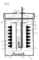
- Fig. 1 shows a device for coating workpieces, which is a preferred embodiment of the invention.
- the coating device has a container 1 which is closed from above by a loosely placed cover 2.
- a propellant gas tube 3 is guided from above through the lid 2 into the interior of the container 1 and opens into the lower region of the container just above the container bottom 11.
- the propellant gas tube 3 runs vertically from top to bottom in the edge region of the container 1, parallel to a side wall 12 of the container 1.
- a Venturi nozzle 4 is arranged, the nozzle opening 41 facing away from the side wall 12, so that gas flowing out through the nozzle opening 41 flows parallel to the container bottom 11, as shown by the arrows.
- a cromegranate 51 which is mixed with powdered NH 4 Cl, which serves as an activator.
- the container bottom 11 is covered with the chrome granules 51 and the activator, and the venturi nozzle 4 is arranged near the side wall 12 of the container 1 such that propellant gas flowing out through the venturi nozzle 4 sweeps over the chrome granules 51 and the activator.
- a holding device 6 for holding or carrying several workpieces 61 to be coated, in the present case turbine blades, arranged.
- the workpieces are at different levels held in container 1, with approximately the entire interior of container 1 is exploited.
- the workpieces or turbine blades 61 are parallel mounted to each other in a horizontal orientation in the holding device 6.
- the Holding device 6 is designed in the form of a framework so that it is on its sides is open (not shown in the figure), in order to provide the coating gas with as free access as possible to ensure the blade surfaces.
- a guide plate 7a, 7b at the upper end of the holding device 6 is designed as a flat plate or disk and parallel to the container bottom 11 or is arranged to the container lid 2 in a horizontal orientation.
- baffles 7a, 7b are arranged holes, not shown in the figure, so that coating gas flow through the guide plates 7a, 7b in the vertical direction can.
- the baffles 7a, 7b serve as distributor orifices to block the gas flow in the upper and in the lower area of the container 1 parallel to the container base 11 and Container lid 2, d. H. in the horizontal direction, to conduct and evenly over the to distribute chrome granules 51 and the activator lying on the container bottom 11.
- an exhaust gas opening 21 for Derivation of the propellant gas.
- the coating method according to the invention is described below using the Chromating turbine blades described as workpieces 61.
- argon is used as the propellant gas through the propellant tube 3 in the Container 1 initiated, as indicated by arrow A, the container 1 in a furnace retort or heating device, not shown, is at a temperature is heated from approx. 1100 ° C.
- the argon flows through the LPG tube 3 and the Venturi nozzle 4 arranged at its end. When passing through the LPG tube 3, the argon is heated up and undergoes thermal expansion or pressure increase in the end area of the LPG tube 3.
- the argon flows in a horizontal direction parallel to the nozzle opening 41
- Gaseous material is formed over the chrome granules 51 Chromium chloride as a coating gas.
- the coating gas is together with the propellant gas on the side wall 13 of the container opposite the Venturi nozzle 4 1 parallel to this vertically directed upwards and in the upper area of the Container 1 between the upper baffle 7b and the container lid 2 horizontally passed to the opposite side to the side wall 12.
- the coating gas is heavier than the propellant gas, a takes place in the upper region of the container 1 Separation or separation of the propellant gas from the coating gas, so that the lighter propellant gas can escape from the exhaust opening 21 upwards.
- the heavier chromium chloride flows through the holes in the guide plate 7b and in the area of the propellant gas tube 3 along the side wall 12 down so that it comes into contact with the surfaces of the turbine blades. This diffuses Chromium in the workpiece or blade surfaces, whereby by the circulation cavities in the interior of the blades are evenly distributed come into contact with the coating gas.
- the Reactor vessel 1 has a diameter of 500 mm and a height of 810 mm.
- the LPG tube 3 is made of ceramic, so as not to be damaged by the HCl.
- this is done by the propellant gas escaping the exhaust gas opening 21 is pumped outside the container and fed back to the container via the propellant tube 3.
- the method is preferably carried out in such a way that at certain time intervals, preferably every 10 minutes, for a period of about 10 seconds.
- Propellant pumped in is, in the present case, the circulation during the supply of propellant gas with a propellant gas throughput of approx. 800 - 1000 l per hour becomes.
- the dilution of the coating gas is achieved by the pulsed propellant gas supply kept low and advantageous flow conditions for diffusion coating with a uniform distribution of the coating gas in reached the entire interior of the container 1.
- the propellant gas is circulated without mechanically moving components be used. This is particularly advantageous at very high temperatures, since no damage to bearings or rotating and sliding bushings Retort and reactor or container 1, e.g. B.
- the Venturi nozzle 4 arranged at the end of the propellant gas tube 3 is oriented so that that its nozzle opening 41 upwards in the direction of the exhaust opening 21 points.
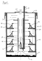
- the Venturi nozzle 4 is located in the middle between the side walls 12 of the cylindrical container 1 and is arranged in the lower region of the container 1.
- the Venturi nozzle 4 is located within the channel 8 in its lower region, the nozzle opening 41 in Longitudinal direction of the channel towards its upper end.
- On the outside of the Channel wall in the upper area of the channel is an annular, flat distribution panel 9 arranged, which is oriented horizontally and partly over the Turbine blades 61 arranged vertically in the container 1.
- the container 1 has a diameter of 500 mm and a height of 810 mm and at its Base 11 is the chrome granules 51 with the activator.
- Several turbine blades 61 are aligned parallel to one another and about the central axis A of the Container 1 or the channel 8 located there arranged around.
- argon When circulating, argon is passed through the propellant tube 3 into the container 1 and escapes through the nozzle opening 41 of the Venturi nozzle 4 within the channel 8 upwards so that it flows vertically upwards into the channel 8.
- the Venturi nozzle 4 becomes coating gas at the lower opening 81 of the channel 8 sucked into channel 8 and together with the propellant in channel 8 to the top Channel opening 82 passed.
- the lighter part separates in the upper region of the container 1 Propellant gas from the heavier coating gas and escapes through the exhaust opening 21.
- the heavier coating gas is between the reactor cover 2 and the distributor panel 9 is guided radially outwards to the wall 12 of the container 1 and falls in between the wall of the channel 8 and the side wall 12 Areas of the container 1 down, whereby it flows around the turbine blades 61.
- the gas In the vicinity of the bottom 11 of the container 1, the gas in turn strikes the Chromium granules 51, the surface of which is radially inward in the horizontal direction sweeps, then re-enter the channel 8 at its lower opening 81.
- the chroming of the gymnastics blades is in this way at approx. 1220 ° C carried out. Due to the vertical arrangement of the turbine blades and the vertical or vertical gas circulation can in particular hollow spaces inside of the turbine blades 61, which extend in the longitudinal direction thereof, evenly and coated with a constant layer thickness.
- FIG. 3 schematically shows a still further preferred embodiment of the invention
- Coating device which in this case is used for the alitation of Blades are used.
- a CA50 granulate 53 is put together with an activator on the container bottom 11 on the inside of the container 1.
- CA50 granules 53 arranged in basket-like donor containers 56.
- the propellant tube 3, the Venturi nozzle 4, and the channel 8 with the distributor orifice 9 are arranged as in the embodiment described in FIG. 2.
- In the annulus between the wall of the channel 8 and the side wall 12 of the cylindrical Container 1 are a plurality of turbine blades 61 one above the other in different heights or levels of the container 1 arranged horizontally.
- the blade arrangement is held in the container 1 by a charging frame 62.
- the coating gas flows from the granulate 53 in the upper one Region of the container downward, flowing past the turbine blades 61.
- the Coating gas propellant in the form of argon through the propellant tube 3 and Venturi nozzle 4
- the light propellant gas is separated from the heavy coating gas, with the propellant gas through the exhaust opening 21 escapes upwards, while the heavier coating gas along the Turbine blades 61 falls down, where it hits the bottom of the tank again 11 lying CA50 granules 53 and the activator. Then it flows Coating gas radially inward and re-enters the opening below 81 of channel 8.
- Fig. 4 shows schematically a coating device according to the invention for Alit, whereby an aluminum melt 54 is used as donor material.
- the gas flow in the container is as in the previous figures through the Arrows marked.
- the structure is similar to that of the embodiment shown in FIG. 3, however, instead of the granulate, the aluminum melt 54 is together arranged with an activator in the interior of the container 1 on its bottom 11.
- the aluminum melt 54 and the activator are in a donor container 54a, which has a circular wall and below the opening 81 of the channel 8 is arranged.
- the propellant gas is together with the coating gas inside of the channel 8 passed up into the upper region of the container 1, where the separates lighter propellant from heavier coating gas.
- the coating gas flows radially parallel to the charging frame 62 the middle of the container 1 to the outside to its side walls 12 and falls there below, past the turbine blades 61.
- the gas stream hits the tank bottom 11 on the aluminum melt 54 with the activator, causing it to re-aluminum picks up the next circulation on the surfaces of the turbine blades 61 is deposited.
- the process is carried out at 1100 ° C to approx. 1230 ° C carried out, thereby also a circulation of the coating gas Layer gradient and thus different layer thicknesses can be avoided without that mechanically moved components, bearings, seals, etc. must be used.
- FIG. 5 shows yet another preferred embodiment of the invention Coating device used here for alitation. Also located here there is an aluminum melt 54 and an activator on the container bottom 11 in a donor container 54a, which is arranged in the center on the container bottom 11 is.
- a rotatable disk 30 is arranged in the upper region of the container, which is aligned horizontally and runs parallel to the lid 2 of the container 1.
- a shaft 31 is fixed to the disc 30 and extends vertically to this in the direction of the longitudinal axis L of the container 1 through an opening 32 in the middle of the container lid 2.
- the shaft 31 has a large diameter and a lot of play in the area of the opening 32 to prevent damage even at high temperatures or wear in the area of the shaft 31 or the opening 32 to avoid due to thermal expansion.
- the rotating disk 30 as a means for circulating the coating gas will result in increased wear or material damage the high temperatures in the reactor room avoided, which is an advantage over the use of e.g. B. represents a propeller.
- a rotation of the Disc adhere the gas particles to the surface of disc 30 and move due to the centrifugal force to the outside edge of the disk 30. Due to the surface adhesion of the gas particles on the rotating disk 30 and Friction between the gas particles creates a laminar flow from the center the disc 30 is directed radially outwards.
- the rotating disc 30 is made of a nickel-based alloy, it can however, it can also be made of ceramic.
- the mechanical gas circulation has the advantage that no additional gas is the coating gas diluted, and thus the total coating activity to be coated Components is available.
- By running with a very large shaft 31 with great play will damage the shaft and avoided by the cover 2.
- By executing with A rotating disc is subject to wear even at high temperatures reduced.
- a propeller can also be used instead of a rotating disk 30 made of a durable material, such as e.g. Ceramic, made is.
- the retort not shown in the figures, in which the container 1 or reactor is located, is charged with gas, for example with Ar or H 2 .
- gas for example with Ar or H 2 .
- the interior of the container 1 and the interior of the retort are advantageously at the same or approximately the same pressure level, so that with a mechanical circulation device a large play of the shaft 31 in the container lid 2 is possible without the quality of the coating gas being adversely affected.
- the reactor or container 1 is placed in the furnace retort and annealed for a certain time under argon or H 2 .
- Fig. 6 shows yet another coating device according to the invention, which for Chroming of housing parts is used.
- Inside of the side wall 12 of the cylindrical container 1 are support devices 71 at different heights of the interior or usable space of the container 1 arranged. Housing rings 72 to be coated (In 909, HDV Level 5).
- the propellant argon supplied from above flows out of the nozzle opening 41 and goes up in the channel 8 in the center of the container 1, and is separated from the coating gas because of its lower weight.
- the Coating gas flows radially outward and in the upper area of the container the sidewall 12 of the container vertically downward, being the housing rings 72 happened and at the bottom of the container 1 on the chrome granules 51 and the activator hits, then due to the action of the Venturi nozzle again in the channel 8 on his lower opening 81 to enter.
- the present invention can be used to apply both metallic diffusion layers, overlay layers with no to little diffusion and ceramic CVD layers.
- zirconium from Zr (dmhg) 4 can be evaporated and passed to the components to be coated in a reactor at a higher temperature.
- Zr can be evaporated from Zr (dmhg) 4 , passed to the components with argon and O 2 doping in a reactor and deposited as ZrO 2 .
- Y can also be evaporated from Y (tmhd) 3 and passed to the components with argon and O 2 doping in a reactor and deposited as Y 2 O 3 .
- the advantage of these processes is that they run at low process temperatures.
- Inorganic compounds such as TIBA in the form of a liquid, evaporate at approx. 80 ° C, the resulting gas flows into the reactor and acts on the workpieces to be coated. Circulation is also possible here, for example with a disk, a propeller or with propellant.
- the present invention makes it uniform even at high temperatures Coating reached and a layer gradient on the coated component or workpiece is largely avoided.
- a uniform coating gas concentration is ensured without excessive dilution occurring and without the need for complex constructions which are also cost-intensive and prone to failure.
- the installation of one or more Venturi nozzles is easy and can be accomplished with little resources.
- a lower dilution of the coating gas is achieved by using inert propellant gases, e.g. B. Ar, He, Kr, Ne, etc. achieved.
- inert propellant gases e.g. B. Ar, He, Kr, Ne, etc.
- H 2 as a propellant if the formation of HF or HCl is desired from the coating process.
- the gas phase coating method according to the invention and the one according to the invention also offers a high degree of flexibility, since existing systems are easy to retrofit and materials coated with different geometries can be without a special design of the device or complex adjustment of the device is necessary. Even cavities and channels inside turbine blades can thus be coated, being uneven Layer thicknesses are largely avoided.
Landscapes
- Chemical & Material Sciences (AREA)
- Chemical Kinetics & Catalysis (AREA)
- Engineering & Computer Science (AREA)
- Materials Engineering (AREA)
- Mechanical Engineering (AREA)
- Metallurgy (AREA)
- Organic Chemistry (AREA)
- General Chemical & Material Sciences (AREA)
- Inorganic Chemistry (AREA)
- Other Surface Treatments For Metallic Materials (AREA)
- Application Of Or Painting With Fluid Materials (AREA)
Applications Claiming Priority (2)
| Application Number | Priority Date | Filing Date | Title |
|---|---|---|---|
| DE19803740A DE19803740C2 (de) | 1998-01-30 | 1998-01-30 | Gasphasenbeschichtungsverfahren und Vorrichtung zur Gasphasenbeschichtung von Werkstücken |
| DE19803740 | 1998-01-30 |
Publications (2)
| Publication Number | Publication Date |
|---|---|
| EP0933445A1 true EP0933445A1 (fr) | 1999-08-04 |
| EP0933445B1 EP0933445B1 (fr) | 2003-04-09 |
Family
ID=7856222
Family Applications (1)
| Application Number | Title | Priority Date | Filing Date |
|---|---|---|---|
| EP99100905A Expired - Lifetime EP0933445B1 (fr) | 1998-01-30 | 1999-01-20 | Procédé et dispositif pour le revêtement de pieces par dépôt chimique en phase vapeur |
Country Status (4)
| Country | Link |
|---|---|
| US (1) | US6203851B1 (fr) |
| EP (1) | EP0933445B1 (fr) |
| DE (1) | DE19803740C2 (fr) |
| ES (1) | ES2195456T3 (fr) |
Cited By (2)
| Publication number | Priority date | Publication date | Assignee | Title |
|---|---|---|---|---|
| EP1816232A1 (fr) * | 2006-01-31 | 2007-08-08 | COTEC GmbH | Dispositif et procédé destinés au revêtement d'objets sur toutes les faces |
| WO2010048932A1 (fr) * | 2008-10-28 | 2010-05-06 | Mtu Aero Engines Gmbh | Couche de protection contre la corrosion à haute température et procédé de fabrication |
Families Citing this family (15)
| Publication number | Priority date | Publication date | Assignee | Title |
|---|---|---|---|---|
| DE10036620C2 (de) * | 2000-07-27 | 2002-09-26 | Mtu Aero Engines Gmbh | Verfahren und Vorrichtung zum Chromieren einer inneren Oberfläche eines Bauteils |
| US6986814B2 (en) | 2001-12-20 | 2006-01-17 | General Electric Company | Gas distributor for vapor coating method and container |
| DE10258560A1 (de) * | 2002-12-14 | 2004-07-08 | Mtu Aero Engines Gmbh | Verfahren und Vorrichtung zum CVD-Beschichten von Werkstücken |
| US6929825B2 (en) * | 2003-02-04 | 2005-08-16 | General Electric Company | Method for aluminide coating of gas turbine engine blade |
| US7026011B2 (en) | 2003-02-04 | 2006-04-11 | General Electric Company | Aluminide coating of gas turbine engine blade |
| US6905730B2 (en) * | 2003-07-08 | 2005-06-14 | General Electric Company | Aluminide coating of turbine engine component |
| EP1666625A1 (fr) * | 2004-12-01 | 2006-06-07 | Siemens Aktiengesellschaft | Procédé de revêtement d'un composant a l'interieur d'un aparat |
| US20090304918A1 (en) * | 2005-04-25 | 2009-12-10 | Georg Mayer | Method and apparatus for coating objects |
| GB2432371B (en) * | 2005-11-17 | 2011-06-15 | Epichem Ltd | Improved bubbler for the transportation of substances by a carrier gas |
| CN102597310B (zh) | 2009-11-02 | 2015-02-04 | 西格玛-奥吉奇有限责任公司 | 固态前体输送组件以及相关方法 |
| FR2992977B1 (fr) * | 2012-07-03 | 2017-03-10 | Snecma | Procede et outillage pour le depot d'un revetement metallique en phase vapeur sur des pieces en super alliages |
| DE102018202297A1 (de) * | 2018-02-15 | 2019-08-22 | MTU Aero Engines AG | Vorrichtung und Verfahren zum Gasphasenbeschichten von Werkstücken |
| US11028480B2 (en) | 2018-03-19 | 2021-06-08 | Applied Materials, Inc. | Methods of protecting metallic components against corrosion using chromium-containing thin films |
| DE102018221579A1 (de) * | 2018-12-13 | 2020-06-18 | MTU Aero Engines AG | Vorrichtung und Verfahren zum Gasphasenbeschichten von Werkstücken |
| US11466364B2 (en) | 2019-09-06 | 2022-10-11 | Applied Materials, Inc. | Methods for forming protective coatings containing crystallized aluminum oxide |
Citations (3)
| Publication number | Priority date | Publication date | Assignee | Title |
|---|---|---|---|---|
| US2650564A (en) * | 1949-12-02 | 1953-09-01 | Ohio Commw Eng Co | Dynamic pyrolytic plating apparatus |
| DE1265530B (de) * | 1961-11-29 | 1968-04-04 | Wilson Eng Co Inc Lee | Vorrichtung zum Gasplattieren einer Metallbandspule |
| JPS62149883A (ja) * | 1986-10-20 | 1987-07-03 | Hitachi Chem Co Ltd | 化学気相蒸着装置 |
Family Cites Families (8)
| Publication number | Priority date | Publication date | Assignee | Title |
|---|---|---|---|---|
| JPH0645881B2 (ja) * | 1986-03-28 | 1994-06-15 | 日本鋼管株式会社 | 連続処理ラインにおける鋼板の浸珪処理方法 |
| DE4035789C1 (fr) * | 1990-11-10 | 1991-06-13 | Mtu Muenchen Gmbh | |
| DE4119967C1 (fr) * | 1991-06-18 | 1992-09-17 | Mtu Muenchen Gmbh | |
| JP2650513B2 (ja) * | 1991-06-24 | 1997-09-03 | 財団法人国際超電導産業技術研究センター | Bi−Sr−Ca−Cu−O系超電導膜の製造方法 |
| US5221354A (en) * | 1991-11-04 | 1993-06-22 | General Electric Company | Apparatus and method for gas phase coating of hollow articles |
| FR2707671B1 (fr) * | 1993-07-12 | 1995-09-15 | Centre Nat Rech Scient | Procédé et dispositif d'introduction de précurseurs dans une enceinte de dépôt chimique en phase vapeur. |
| CH690857A5 (de) * | 1995-07-04 | 2001-02-15 | Erich Bergmann | Anlage zur plasmaunterstützten physikalischen Hochvakuumbedampfung von Werkstücken mit verschleissfesten Schichten und Verfahren zur Durchführung in dieser Anlage |
| DE19607625C1 (de) * | 1996-02-29 | 1996-12-12 | Mtu Muenchen Gmbh | Vorrichtung und Verfahren zur Präparation und/oder Beschichtung der Oberflächen von Hohlbauteilen |
-
1998
- 1998-01-30 DE DE19803740A patent/DE19803740C2/de not_active Expired - Fee Related
-
1999
- 1999-01-20 EP EP99100905A patent/EP0933445B1/fr not_active Expired - Lifetime
- 1999-01-20 ES ES99100905T patent/ES2195456T3/es not_active Expired - Lifetime
- 1999-01-28 US US09/239,130 patent/US6203851B1/en not_active Expired - Lifetime
Patent Citations (3)
| Publication number | Priority date | Publication date | Assignee | Title |
|---|---|---|---|---|
| US2650564A (en) * | 1949-12-02 | 1953-09-01 | Ohio Commw Eng Co | Dynamic pyrolytic plating apparatus |
| DE1265530B (de) * | 1961-11-29 | 1968-04-04 | Wilson Eng Co Inc Lee | Vorrichtung zum Gasplattieren einer Metallbandspule |
| JPS62149883A (ja) * | 1986-10-20 | 1987-07-03 | Hitachi Chem Co Ltd | 化学気相蒸着装置 |
Non-Patent Citations (2)
| Title |
|---|
| GARCIA G ET AL: "PREPARATION OF YSZ LAYERS BY MOCVD: INFLUENCE OF EXPERIMENTAL PARAMETERS ON THE MORPHOLOGY OF THE FILMS", JOURNAL OF CRYSTAL GROWTH, vol. 156, no. 4, 1 December 1995 (1995-12-01), pages 426 - 432, XP004000432 * |
| PATENT ABSTRACTS OF JAPAN vol. 011, no. 381 (C - 464) 12 December 1987 (1987-12-12) * |
Cited By (2)
| Publication number | Priority date | Publication date | Assignee | Title |
|---|---|---|---|---|
| EP1816232A1 (fr) * | 2006-01-31 | 2007-08-08 | COTEC GmbH | Dispositif et procédé destinés au revêtement d'objets sur toutes les faces |
| WO2010048932A1 (fr) * | 2008-10-28 | 2010-05-06 | Mtu Aero Engines Gmbh | Couche de protection contre la corrosion à haute température et procédé de fabrication |
Also Published As
| Publication number | Publication date |
|---|---|
| EP0933445B1 (fr) | 2003-04-09 |
| US6203851B1 (en) | 2001-03-20 |
| ES2195456T3 (es) | 2003-12-01 |
| DE19803740C2 (de) | 2001-05-31 |
| DE19803740A1 (de) | 1999-08-05 |
Similar Documents
| Publication | Publication Date | Title |
|---|---|---|
| EP0933445A1 (fr) | Procédé et dispositif pour le revêtement de pieces par dépÔt chimique en phase vapeur | |
| DE3015300C2 (de) | Mikrowellenofen | |
| DE3109513C2 (de) | Verfahren und Vorrichtung zur Mikrowellen-Wärmebehandlung | |
| DE69503624T2 (de) | Senkrecht abgestufter polykondensationsreaktor beinhaltend reaktorböden mit geteiltem fluss | |
| DE2034404C3 (de) | Gießofen für die Herstellung gefügeorientierter Gußstücke | |
| DE102008058330A1 (de) | Verfahren zur Temperierung einer Heiß isostatischen Presse und eine Heiß isostatische Presse | |
| DE3215509C2 (fr) | ||
| DE102008058329A1 (de) | Verfahren zur Temperierung einer Heiß Isostatischen Presse und eine Heiß Isostatische Presse | |
| CH619867A5 (fr) | ||
| DE1433737A1 (de) | Verguetungsofen | |
| DE60215588T2 (de) | Beweglicher Herdofen und Verfahren zur Herstellung von reduzierten Metallaglomeraten | |
| DE2907139A1 (de) | Apparat zum sulfatisierenden roesten von feinkoernigem selenhaltigem rohmaterial | |
| DE19625264A1 (de) | Reaktor für korrosive Reaktionsmischungen | |
| DE69910698T2 (de) | Vorrichtung zur Verhinderung von Kohlenstoffablagerungen auf festen Gegenständen | |
| DD157966A3 (de) | Verfahren und vorrichtungen zur verfestigung von glaserzeugnissen durch ionenaustauch | |
| EP2470678A1 (fr) | Dispositif de dégazage d'une masse d'acier en fusion comprenant un tube de sortie amélioré | |
| DE4035155C2 (de) | Anlage zum Vergüten von Kleinteilen aus Metall | |
| DE1929476A1 (de) | Vorrichtung zur Herstellung von feuerfesten Formmasken | |
| DE4229198C2 (de) | Rührer eines Drehherdofens | |
| DE402518C (de) | Ringmuffelofen | |
| DE2012020A1 (de) | Wärmetauscher oder Ofen mit umlaufendem ringförmigem Boden | |
| DE2408713C3 (de) | Verteilervorrichtung für die Aufgabebunker eines Elektrolichtbogenofens | |
| DE1792527C3 (de) | Vorrichtung zum Lösungsmitteloder (Seruchsfreimachen von partikelförml0em organischem Material | |
| DE2060229C3 (de) | Verfahren und Vorrichtung zur Gewinnung harter Gußstucke aus Vor legierungen | |
| DE2611990C2 (de) | Brennstoffbeheizter Wärmebehandlungsofen für metallisches oder keramisches Gut |
Legal Events
| Date | Code | Title | Description |
|---|---|---|---|
| PUAI | Public reference made under article 153(3) epc to a published international application that has entered the european phase |
Free format text: ORIGINAL CODE: 0009012 |
|
| AK | Designated contracting states |
Kind code of ref document: A1 Designated state(s): ES FR GB IT |
|
| AX | Request for extension of the european patent |
Free format text: AL;LT;LV;MK;RO;SI |
|
| 17P | Request for examination filed |
Effective date: 19991005 |
|
| AKX | Designation fees paid |
Free format text: ES FR GB IT |
|
| REG | Reference to a national code |
Ref country code: DE Ref legal event code: 8566 |
|
| RAP1 | Party data changed (applicant data changed or rights of an application transferred) |
Owner name: MTU AERO ENGINES GMBH |
|
| 17Q | First examination report despatched |
Effective date: 20010320 |
|
| GRAG | Despatch of communication of intention to grant |
Free format text: ORIGINAL CODE: EPIDOS AGRA |
|
| GRAG | Despatch of communication of intention to grant |
Free format text: ORIGINAL CODE: EPIDOS AGRA |
|
| GRAH | Despatch of communication of intention to grant a patent |
Free format text: ORIGINAL CODE: EPIDOS IGRA |
|
| GRAH | Despatch of communication of intention to grant a patent |
Free format text: ORIGINAL CODE: EPIDOS IGRA |
|
| GRAA | (expected) grant |
Free format text: ORIGINAL CODE: 0009210 |
|
| AK | Designated contracting states |
Designated state(s): ES FR GB IT |
|
| REG | Reference to a national code |
Ref country code: GB Ref legal event code: FG4D Free format text: NOT ENGLISH |
|
| GBT | Gb: translation of ep patent filed (gb section 77(6)(a)/1977) | ||
| ET | Fr: translation filed | ||
| PLBE | No opposition filed within time limit |
Free format text: ORIGINAL CODE: 0009261 |
|
| STAA | Information on the status of an ep patent application or granted ep patent |
Free format text: STATUS: NO OPPOSITION FILED WITHIN TIME LIMIT |
|
| 26N | No opposition filed |
Effective date: 20040112 |
|
| PGFP | Annual fee paid to national office [announced via postgrant information from national office to epo] |
Ref country code: IT Payment date: 20140124 Year of fee payment: 16 Ref country code: ES Payment date: 20140122 Year of fee payment: 16 Ref country code: FR Payment date: 20140124 Year of fee payment: 16 |
|
| PGFP | Annual fee paid to national office [announced via postgrant information from national office to epo] |
Ref country code: GB Payment date: 20140123 Year of fee payment: 16 |
|
| GBPC | Gb: european patent ceased through non-payment of renewal fee |
Effective date: 20150120 |
|
| PG25 | Lapsed in a contracting state [announced via postgrant information from national office to epo] |
Ref country code: GB Free format text: LAPSE BECAUSE OF NON-PAYMENT OF DUE FEES Effective date: 20150120 |
|
| REG | Reference to a national code |
Ref country code: FR Ref legal event code: ST Effective date: 20150930 |
|
| PG25 | Lapsed in a contracting state [announced via postgrant information from national office to epo] |
Ref country code: FR Free format text: LAPSE BECAUSE OF NON-PAYMENT OF DUE FEES Effective date: 20150202 |
|
| PG25 | Lapsed in a contracting state [announced via postgrant information from national office to epo] |
Ref country code: IT Free format text: LAPSE BECAUSE OF NON-PAYMENT OF DUE FEES Effective date: 20150120 |
|
| REG | Reference to a national code |
Ref country code: ES Ref legal event code: FD2A Effective date: 20160226 |
|
| PG25 | Lapsed in a contracting state [announced via postgrant information from national office to epo] |
Ref country code: ES Free format text: LAPSE BECAUSE OF NON-PAYMENT OF DUE FEES Effective date: 20150121 |