EP0933476A2 - Vorrichtung zur Beschädigung bzw. Zerstörung von Reifen eines Kraftfahrzeuges - Google Patents
Vorrichtung zur Beschädigung bzw. Zerstörung von Reifen eines Kraftfahrzeuges Download PDFInfo
- Publication number
- EP0933476A2 EP0933476A2 EP99890017A EP99890017A EP0933476A2 EP 0933476 A2 EP0933476 A2 EP 0933476A2 EP 99890017 A EP99890017 A EP 99890017A EP 99890017 A EP99890017 A EP 99890017A EP 0933476 A2 EP0933476 A2 EP 0933476A2
- Authority
- EP
- European Patent Office
- Prior art keywords
- carrier
- scissor
- control device
- claws
- lattice
- Prior art date
- Legal status (The legal status is an assumption and is not a legal conclusion. Google has not performed a legal analysis and makes no representation as to the accuracy of the status listed.)
- Withdrawn
Links
Images


Classifications
-
- E—FIXED CONSTRUCTIONS
- E01—CONSTRUCTION OF ROADS, RAILWAYS, OR BRIDGES
- E01F—ADDITIONAL WORK, SUCH AS EQUIPPING ROADS OR THE CONSTRUCTION OF PLATFORMS, HELICOPTER LANDING STAGES, SIGNS, SNOW FENCES, OR THE LIKE
- E01F13/00—Arrangements for obstructing or restricting traffic, e.g. gates, barricades ; Preventing passage of vehicles of selected category or dimensions
- E01F13/10—Vehicle barriers specially adapted for allowing passage in one direction only
- E01F13/105—Vehicle barriers specially adapted for allowing passage in one direction only depressible by right-way traffic, e.g. pivotally; actuated by wrong-way traffic
-
- E—FIXED CONSTRUCTIONS
- E01—CONSTRUCTION OF ROADS, RAILWAYS, OR BRIDGES
- E01F—ADDITIONAL WORK, SUCH AS EQUIPPING ROADS OR THE CONSTRUCTION OF PLATFORMS, HELICOPTER LANDING STAGES, SIGNS, SNOW FENCES, OR THE LIKE
- E01F13/00—Arrangements for obstructing or restricting traffic, e.g. gates, barricades ; Preventing passage of vehicles of selected category or dimensions
- E01F13/12—Arrangements for obstructing or restricting traffic, e.g. gates, barricades ; Preventing passage of vehicles of selected category or dimensions for forcibly arresting or disabling vehicles, e.g. spiked mats
- E01F13/123—Arrangements for obstructing or restricting traffic, e.g. gates, barricades ; Preventing passage of vehicles of selected category or dimensions for forcibly arresting or disabling vehicles, e.g. spiked mats depressible or retractable below the traffic surface, e.g. one-way spike barriers, power-controlled prong barriers
Definitions
- the subject invention relates to a device for damage or destruction of tires of a motor vehicle, which over a road is operated with a scissor-type carrier for claws, Tips or the like, which is adjustable across the road.
- a device which has a rocker formed with claws which, if from a vehicle of the wrong one Is driven here, is pivoted into such a position that their Claws penetrate into the wheels of the vehicle and destroy them.
- the device is disadvantageous in that it is transverse to one another Roadway-extending channel must be installed as it is a strong one Causes noise since it has to be serviced in winter to ensure their functionality and because they Vehicles that drive over them are pivoted, causing them is subject to high wear.
- a device which with a scissor-like carrier for tips, which is across a roadway can be adjusted to motor vehicles by which this device is run over to standstill bring that their tires through the penetrating tips so badly damaged that these vehicles are no longer functional are.
- This known device is at one of the two ends with two handles formed by which the scissor-lattice carrier from his Closed position can be adjusted to its open position.
- This known device is also disadvantageous because it with rigid protruding tips is formed, which makes the tires of any about these moving vehicles, regardless of the direction they move, are destroyed.
- the object of the invention is based on the object to create such a device, which at very high speed which is adjustable from its closed position to its open position can be of such a great length that they can also be used on wide roads can be used and by which preferably only destroyed the tires of motor vehicles traveling in one direction above it whereas the tires from in the opposite direction driving motor vehicles are not destroyed.
- At least a control device is provided, the output of which is sent to an actuating device is performed for the scissors-like support and that preferably the claws, tips or the like. are arranged pivotably on the carrier, being moved into a by vehicles moving in a first direction ineffective position are pivoted, whereas in the tires of themselves penetrate vehicles moving in the other direction and damage them or destroy.
- the control device can by a Sensor device or be formed by a remote control device.
- Such a device is particularly suitable for use on downhill runs of highways suitable to thereby drive onto motor vehicles to prevent the wrong lane.
- Such a device is equally suitable for the construction of roadblocks, e.g. in the event of vehicle checks by the police. This can Device from its closed position to its open position within a very short time brought to stop vehicles.
- the control device is preferably by at least one in the roadway arranged induction loop, by at least one light barrier or formed by at least one radar detector.
- the actuator for the scissor-lattice-like carrier can by a spring accumulator, a pneumatic cylinder, a hydraulic cylinder or an electric motor be educated.
- at least one warning system, a photo system or a television camera and or or at least one transmitter be provided, which to trigger the at least one control device to serve.
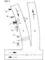
- a first lane is used A, which can be driven in both directions, a second Lane B, which may only be driven in one direction B1, and ends in lane A, a third lane C, which only in the driving in the opposite direction C1.
- the two lanes B and C can be the entrance to a highway and the exit from a freeway pose.
- This is with a system equipped by which the tires of a motor vehicle, which this Driving in the wrong direction, damaged or destroyed.
- this system contains sensors which are formed by induction loops 11 embedded in the floor of the third roadway C or by at least one detector 12.
- this system contains a scissor-lattice-like carrier 2 for a large number of claws or tips.
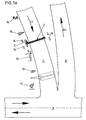
- the carrier 2 is assigned an actuating device 3, which can be activated by the sensors 11 and 12, as a result of which the scissor-lattice-like carrier 2, which is arranged at the edge of the carriageway C and is in its closed position shown in FIG. 1, in its in Fig. 1a shown, open position is transferred, whereby it extends across the road C.
- the actuating device 3 is formed by a spring accumulator, by a pneumatic or hydraulic actuating cylinder or by an electric motor.
- a radio system 13 is provided, which is also triggered by the sensors 11 and 12 and through which a report is made to a police station becomes.
- traffic lights 14 are provided, which are also by the Sensors 11 and 12 are triggered.
- a sensor 15 is provided through which when a motor vehicle is the lattice-like carrier 2 approaches from the right side, is prevented that the carrier 2 in its open position is changed.
- a warning system 16 is also provided, which occurs when the scissor-lattice-like carrier 2 moves into its open position has been activated, whereby the handlebars from the road C in the right direction motor vehicles are warned.
- a photographic camera 17 or a television camera be provided, which is also triggered by the sensors 11 and 12 respectively and by which a wrong-driving vehicle is picked up becomes.
- the scissor-lattice-like carrier 2 is shown in its open position.
- the scissor-lattice-like support 2 consists of a plurality of struts 21, 21a, 21b .... and 22, 22a, 22b bib which cross each other, being pivotably mounted on one another at their crossing points, and at the free ends of other struts are hinged. Skids or rollers can be provided at the free end of the carrier 2.
- the first two struts 21 and 22 are assigned the actuating device 3, by means of which these two struts 21 and 22 can be pivoted, as a result of which the scissor-lattice-like carrier 2 can be moved from its closed position into the open position shown in FIG. 2. In its open position, it extends across lane C.
- a plurality of claws 4 are mounted on the scissor-lattice-like carrier 2 so as to be pivotable about a horizontal axis 41, but the claws 4 can only be pivoted when the scissor-lattice-like carrier 2 is run over by such a vehicle which moves in a first direction.
- the claws 4 are pivoted into an approximately horizontal position, as a result of which the tires 5 can drive over them without penetrating them.
- the claws 4 cannot be pivoted, but are held in an oblique position with respect to the tire 5a by a stop 42, as a result of which they subsequently penetrate into the tires 5a and damage them.
- an alternative embodiment of such claws 4a is shown, which are also pivotable about horizontal axes.
- Such a device can also be used to build roadblocks used, being by remote control from its closed Position is moved to its open position.
- This can Device consisting of the scissor-lattice-like carrier and this assigned actuating device, be designed as a mobile unit, which are placed anywhere on roads or lanes is, then the triggering of the actuating device by means of a manual actuatable control device or by means of a sensor.
Landscapes
- Engineering & Computer Science (AREA)
- Architecture (AREA)
- Civil Engineering (AREA)
- Structural Engineering (AREA)
- Traffic Control Systems (AREA)
- Vehicle Cleaning, Maintenance, Repair, Refitting, And Outriggers (AREA)
Abstract
Description
- Fig. 1
- eine erfindungsgemäße Vorrichtung mit Zusatzeinrichtungen, welche an der Abfahrt einer Autobahn angeordnet ist, bei geschlossener Lage dieser Vorrichtung und in schematischer Darstellung,
- Fig. 1a
- die Vorrichtung gemäß Fig. 1 in ihrer geöffneten Lage,
- Fig. 2
- die erfindungsgemäße Vorrichtung, in gegenüber Fig. 1a vergrößerter Darstellung,
- die Fig. 3 und 3a
- die erfindungsgemäße Vorrichtung in Seitenansicht, in ihren Wirkungen, wenn sie von zwei entgegengesetzten Richtungen befahren wird,
- Fig. 4
- eine andere Ausführungsform einer erfindungsgemäßen Vorrichtung, in Seitenansicht, und
- Fig. 4a
- ein Detail der Vorrichtung gemäß Fig. 4, in Stirnansicht.
An diesem Träger 2 befindet sich eine Vielzahl von Krallen, welche in die Reifen eines Kraftfahrzeuges, durch welches die Fahrbahn C in der falschen Richtung befahren wird, eindringen, wodurch diese so stark beschädigt werden, daß das Kraftfahrzeug nicht mehr weiterfahren kann. Diese Krallen sind anhand der Fig. 3 und 4 erläutert.
Den ersten beiden Streben 21 und 22 ist die Stelleinrichtung 3 zugeordnet, durch welche diese beiden Streben 21 und 22 verschwenkbar sind, wodurch der scherengitterartige Träger 2 aus seiner Schließlage in die in Fig. 2 dargestellten Offenlage bewegbar ist. In seiner Offenlage erstreckt er sich quer über die Fahrbahn C.
In den Fig. 4 und 4a ist eine alternative Ausführungsform von derartigen Krallen 4a dargestellt, welche gleichfalls um horizontale Achsen verschwenkbar sind.
Claims (9)
- Vorrichtung zur Beschädigung bzw. Zerstörung von Reifen eines Kraftfahrzeues, welches über eine Fahrbahn verfahren wird, mit einem scherengitterartigen Träger (2) für Krallen (4), Spitzen od.dgl., welcher quer über die Fahrbahn (C) verstellbar ist, dadurch gekennzeichnet, daß mindestens eine Steuereinrichtung (11, 12) vorgesehen ist, deren Ausgang an eine Stelleinrichtung (3) für den scherengitterartigen Träger (2) geführt ist und daß vorzugsweise die Krallen (4), Spitzen od.dgl. am Träger (2) verschwenkbar angeordnet sind, wobei sie durch ein sich in in einer ersten Richtung bewegendes Fahrzeug in eine unwirksame Lage verschwenkt werden, wogegen sie in die Reifen (5a) eines sich in der anderen Richtung bewegenden Fahrzeuges eindringen und diese beschädigen.
- Vorrichtung nach Patentanspruch 1, dadurch gekennzeichnet, daß die Steuereinrichtung durch eine Sensoreinrichtung bzw. durch eine Fernsteuereinrichtung gebildet ist.
- Vorrichtung nach Patentanspruch 1, dadurch gekennzeichnet, daß die Steuereinrichtung durch mindestens eine in der Fahrbahn angeordnete Induktionsschleife (11), durch mindestens eine Lichtschranke (12) oder durch einen Radardetektor gebildet ist.
- Vorrichtung nach einem der Patentansprüche 1 bis 3, dadurch gekennzeichnet, daß die Stelleinrichtung (3) für den scherengitterartigen Träger (2) durch einen Federspeicher, einen Pneumatikzylinder, einen Hydraulikzylinder oder einen Elektromotor gebildet ist.
- Vorrichtung nach einem der Patentansprüche 1 bis 4, dadurch gekennzeichnet, daß der scherengitterartige Träger (2) an seinem freien Ende mit Gleitkufen oder Rollen ausgebildet ist.
- Vorrichtung nach einem der Patentansprüche 1 bis 5, dadurch gekennzeichnet, daß mindestens eine Warnanlage (14, 16) vorgesehen ist, welche durch die mindestens eine Steuereinrichtung (11, 12) einschaltbar ist.
- Vorrichtung nach einem der Patentansprüche 1 bis 6, dadurch gekennzeichnet, daß eine Sendeanlage (13) vorgesehen ist, welche durch die mindestens eine Steuereinrichtung (11, 12) auslösbar ist.
- Vorrichtung nach einem der Patentansprüche 1 bis 7, dadurch gekennzeichnet, daß eine Photoanlage bzw. Fernsehkamera vorgesehen ist, welche durch die Steuereinrichtung auslösbar ist.
- Vorrichtung nach einem der Patentansprüche 1 bis 8, dadurch gekennzeichnet, daß die Krallen (4), Spitzen od.dgl. mit einem Anschlag (42) ausgebildet sind, durch welche sie bei Einwirken eines Drehmomentes in einer ersten Richtung in einer vom scherengitterartigen Träger (2) schräg abragenden Lage gehalten sind, wogegen sie bei Einwirken eines Drehmomentes in der anderen Richtung in eine Lage angenähert parallel zum scherengitterartigen Träger verschwenkbar sind.
Applications Claiming Priority (2)
| Application Number | Priority Date | Filing Date | Title |
|---|---|---|---|
| AT4298U | 1998-01-28 | ||
| AT4298 | 1998-01-28 |
Publications (2)
| Publication Number | Publication Date |
|---|---|
| EP0933476A2 true EP0933476A2 (de) | 1999-08-04 |
| EP0933476A3 EP0933476A3 (de) | 2002-03-06 |
Family
ID=3479996
Family Applications (1)
| Application Number | Title | Priority Date | Filing Date |
|---|---|---|---|
| EP99890017A Withdrawn EP0933476A3 (de) | 1998-01-28 | 1999-01-26 | Vorrichtung zur Beschädigung bzw. Zerstörung von Reifen eines Kraftfahrzeuges |
Country Status (1)
| Country | Link |
|---|---|
| EP (1) | EP0933476A3 (de) |
Cited By (8)
| Publication number | Priority date | Publication date | Assignee | Title |
|---|---|---|---|---|
| WO2001038644A1 (de) * | 1999-11-24 | 2001-05-31 | Armin Hribernig | Einrichtung zum behindern von auf einer fahrbahn entgegen der dort vorgeschriebenen fahrtrichtung fahrenden kraftfahrzeugen |
| KR100456416B1 (ko) * | 2002-05-17 | 2004-11-10 | 주식회사 한솔비전 | 범법차량 도주방지용 철침장치 |
| WO2005093163A3 (en) * | 2004-03-28 | 2005-12-22 | Israel Aircraft Ind Ltd | Vehicle arrester systems |
| FR2879793A1 (fr) * | 2004-12-17 | 2006-06-23 | Alain Schreurs | Stop roulage a contre sens |
| WO2007067026A1 (es) * | 2005-12-07 | 2007-06-14 | Cidep, S.A. De C.V. | Barrera vehicular retráctil |
| AT505291B1 (de) * | 2007-06-13 | 2008-12-15 | Stefan Ing Allerstorfer | Einrichtung zum verhindern des befahrens von verkehrswegen entgegen der vorgeschriebenen richtung |
| CN102605728A (zh) * | 2012-04-12 | 2012-07-25 | 宁夏电力公司吴忠供电局 | 防止车辆逆向行驶装置 |
| FR3034438A1 (fr) * | 2015-04-02 | 2016-10-07 | Charles Barassi | Dispositif de prevention d'entree a contre-sens d'un vehicule |
Citations (1)
| Publication number | Priority date | Publication date | Assignee | Title |
|---|---|---|---|---|
| GB1480331A (en) | 1974-08-14 | 1977-07-20 | Lowndes R | Device for stopping vehicles |
Family Cites Families (5)
| Publication number | Priority date | Publication date | Assignee | Title |
|---|---|---|---|---|
| US4320380A (en) * | 1980-07-22 | 1982-03-16 | Devices Development Corporation | Electronically controlled safety mechanism for highway exit ramp |
| DE8604514U1 (de) * | 1986-02-20 | 1986-06-26 | Isai, I-Chang, Feng Shan City, Kaohsiung | Tragbare Straßensperre |
| FR2714404A1 (fr) * | 1993-12-24 | 1995-06-30 | Lang Alfred | Appareil conçu pour poser les herses des barrages routiers par moyen mécanique utilisé par la gendarmerie. |
| DE9407152U1 (de) * | 1994-04-29 | 1995-03-30 | Frank, Egon, 97531 Theres | Geisterfahrerschranke |
| AT1551U1 (de) * | 1996-07-03 | 1997-07-25 | Kanzler Otto | Verfahren und vorrichtung zum verhindern des befahrens einer fahrbahn in der falschen richtung |
-
1999
- 1999-01-26 EP EP99890017A patent/EP0933476A3/de not_active Withdrawn
Patent Citations (1)
| Publication number | Priority date | Publication date | Assignee | Title |
|---|---|---|---|---|
| GB1480331A (en) | 1974-08-14 | 1977-07-20 | Lowndes R | Device for stopping vehicles |
Cited By (8)
| Publication number | Priority date | Publication date | Assignee | Title |
|---|---|---|---|---|
| WO2001038644A1 (de) * | 1999-11-24 | 2001-05-31 | Armin Hribernig | Einrichtung zum behindern von auf einer fahrbahn entgegen der dort vorgeschriebenen fahrtrichtung fahrenden kraftfahrzeugen |
| KR100456416B1 (ko) * | 2002-05-17 | 2004-11-10 | 주식회사 한솔비전 | 범법차량 도주방지용 철침장치 |
| WO2005093163A3 (en) * | 2004-03-28 | 2005-12-22 | Israel Aircraft Ind Ltd | Vehicle arrester systems |
| FR2879793A1 (fr) * | 2004-12-17 | 2006-06-23 | Alain Schreurs | Stop roulage a contre sens |
| WO2007067026A1 (es) * | 2005-12-07 | 2007-06-14 | Cidep, S.A. De C.V. | Barrera vehicular retráctil |
| AT505291B1 (de) * | 2007-06-13 | 2008-12-15 | Stefan Ing Allerstorfer | Einrichtung zum verhindern des befahrens von verkehrswegen entgegen der vorgeschriebenen richtung |
| CN102605728A (zh) * | 2012-04-12 | 2012-07-25 | 宁夏电力公司吴忠供电局 | 防止车辆逆向行驶装置 |
| FR3034438A1 (fr) * | 2015-04-02 | 2016-10-07 | Charles Barassi | Dispositif de prevention d'entree a contre-sens d'un vehicule |
Also Published As
| Publication number | Publication date |
|---|---|
| EP0933476A3 (de) | 2002-03-06 |
Similar Documents
| Publication | Publication Date | Title |
|---|---|---|
| DE69307142T2 (de) | Vorrichtung und Verfahren zur Geschwindigkeitskontrolle | |
| EP2071082A2 (de) | Sperrkörper gegen Räder aufweisende Fahrzeuge | |
| DE2546427C2 (de) | Elastischer Leitpfosten für Straßen | |
| EP0933476A2 (de) | Vorrichtung zur Beschädigung bzw. Zerstörung von Reifen eines Kraftfahrzeuges | |
| DE2632313B2 (de) | Anlage zum Üben der Reaktion und des Fahrverhaltens eines Kraftfahrzeuglenkers in einer Notfallsituation | |
| DE3108614A1 (de) | Vorrichtung zum maehen von gras insbesondere unter absperrungen | |
| DE2813035A1 (de) | Scheinwerfer mit aussenseitiger abdeckung fuer kraftfahrzeuge | |
| DE2451743A1 (de) | Verkehrsleiteinrichtung | |
| DE2914708A1 (de) | Vorrichtung zur warnung der fahrer von kraftfahrzeugen | |
| EP0690176B1 (de) | Leitschwellenstrang | |
| DE102009050941A1 (de) | Fahrerassistenzsystem für ein Nutzfahrzeug | |
| DE2313892B2 (de) | In der Fahrbahn angeordnetes, ausfahrbares Verkehrszeichen | |
| DE69803777T2 (de) | Fahrzeug für die verlegung von notpisten | |
| DE69211277T2 (de) | Markierung zum Hinweisen auf einen Fahrbahnwechsel | |
| AT410264B (de) | Einrichtung zum behindern von auf einer fahrbahn entgegen der dort vorgeschriebenen fahrtrichtung fahrenden kraftfahrzeugen | |
| DE2048780B2 (de) | Quer zur Fahrbahn, insbesondere vor Verkehrsampeln angeordnete Absperrvorrichtung | |
| DE2853307A1 (de) | Einrichtung zur verkehrsregelung | |
| DE102019206943A1 (de) | Verfahren zum Einparken eines Fahrzeugs bis zu einem erkannten Reifenanschlagelement in der Parklücke, sowie Parkassistenzsystem | |
| DE4320065A1 (de) | Abschrankung für Parkbereiche für Kraftfahrzeuge | |
| DE3840697A1 (de) | Anlage zum warnen von fahrzeugfuehrern, die sich mit ihrem kraftfahrzeug in falscher fahrtrichtung bewegen | |
| AT1551U1 (de) | Verfahren und vorrichtung zum verhindern des befahrens einer fahrbahn in der falschen richtung | |
| EP1074662A2 (de) | Markierungssystem für mehrspurige Verkehrswege | |
| DE19531952A1 (de) | Fugenschneideeinrichtung für Längs- und Querfugen | |
| DE102020115038B4 (de) | Mobile Straßensperre | |
| CH689308A5 (de) | Verkehrsleitvorrichtung. |
Legal Events
| Date | Code | Title | Description |
|---|---|---|---|
| PUAI | Public reference made under article 153(3) epc to a published international application that has entered the european phase |
Free format text: ORIGINAL CODE: 0009012 |
|
| AK | Designated contracting states |
Kind code of ref document: A2 Designated state(s): AT BE CH CY DE DK ES FI FR GB GR IE IT LI LU MC NL PT SE |
|
| AX | Request for extension of the european patent |
Free format text: AL;LT;LV;MK;RO;SI |
|
| PUAL | Search report despatched |
Free format text: ORIGINAL CODE: 0009013 |
|
| AK | Designated contracting states |
Kind code of ref document: A3 Designated state(s): AT BE CH CY DE DK ES FI FR GB GR IE IT LI LU MC NL PT SE |
|
| AX | Request for extension of the european patent |
Free format text: AL;LT;LV;MK;RO;SI |
|
| RIC1 | Information provided on ipc code assigned before grant |
Free format text: 7E 01F 13/12 A, 7E 01F 13/10 B, 7G 08G 1/056 B |
|
| AKX | Designation fees paid | ||
| REG | Reference to a national code |
Ref country code: DE Ref legal event code: 8566 |
|
| STAA | Information on the status of an ep patent application or granted ep patent |
Free format text: STATUS: THE APPLICATION IS DEEMED TO BE WITHDRAWN |
|
| 18D | Application deemed to be withdrawn |
Effective date: 20020801 |