EP0933527A2 - Fluidbetätigte Drehantriebsvorrichtung - Google Patents
Fluidbetätigte Drehantriebsvorrichtung Download PDFInfo
- Publication number
- EP0933527A2 EP0933527A2 EP98123579A EP98123579A EP0933527A2 EP 0933527 A2 EP0933527 A2 EP 0933527A2 EP 98123579 A EP98123579 A EP 98123579A EP 98123579 A EP98123579 A EP 98123579A EP 0933527 A2 EP0933527 A2 EP 0933527A2
- Authority
- EP
- European Patent Office
- Prior art keywords
- stop
- rotary drive
- piston
- drive device
- stop unit
- Prior art date
- Legal status (The legal status is an assumption and is not a legal conclusion. Google has not performed a legal analysis and makes no representation as to the accuracy of the status listed.)
- Granted
Links
- 239000012530 fluid Substances 0.000 title claims abstract description 15
- 230000033001 locomotion Effects 0.000 claims abstract description 16
- 238000006073 displacement reaction Methods 0.000 claims description 5
- 238000011144 upstream manufacturing Methods 0.000 claims description 2
- 230000007935 neutral effect Effects 0.000 description 3
- 238000010276 construction Methods 0.000 description 2
- 230000003993 interaction Effects 0.000 description 2
- 238000007789 sealing Methods 0.000 description 2
- 238000005352 clarification Methods 0.000 description 1
- 210000001520 comb Anatomy 0.000 description 1
- 238000011161 development Methods 0.000 description 1
- 230000018109 developmental process Effects 0.000 description 1
- 230000035515 penetration Effects 0.000 description 1
- 238000009420 retrofitting Methods 0.000 description 1
- 239000007787 solid Substances 0.000 description 1
Images


Classifications
-
- F—MECHANICAL ENGINEERING; LIGHTING; HEATING; WEAPONS; BLASTING
- F15—FLUID-PRESSURE ACTUATORS; HYDRAULICS OR PNEUMATICS IN GENERAL
- F15B—SYSTEMS ACTING BY MEANS OF FLUIDS IN GENERAL; FLUID-PRESSURE ACTUATORS, e.g. SERVOMOTORS; DETAILS OF FLUID-PRESSURE SYSTEMS, NOT OTHERWISE PROVIDED FOR
- F15B15/00—Fluid-actuated devices for displacing a member from one position to another; Gearing associated therewith
- F15B15/02—Mechanical layout characterised by the means for converting the movement of the fluid-actuated element into movement of the finally-operated member
- F15B15/06—Mechanical layout characterised by the means for converting the movement of the fluid-actuated element into movement of the finally-operated member for mechanically converting rectilinear movement into non- rectilinear movement
- F15B15/065—Mechanical layout characterised by the means for converting the movement of the fluid-actuated element into movement of the finally-operated member for mechanically converting rectilinear movement into non- rectilinear movement the motor being of the rack-and-pinion type
-
- F—MECHANICAL ENGINEERING; LIGHTING; HEATING; WEAPONS; BLASTING
- F03—MACHINES OR ENGINES FOR LIQUIDS; WIND, SPRING, OR WEIGHT MOTORS; PRODUCING MECHANICAL POWER OR A REACTIVE PROPULSIVE THRUST, NOT OTHERWISE PROVIDED FOR
- F03C—POSITIVE-DISPLACEMENT ENGINES DRIVEN BY LIQUIDS
- F03C1/00—Reciprocating-piston liquid engines
- F03C1/02—Reciprocating-piston liquid engines with multiple-cylinders, characterised by the number or arrangement of cylinders
-
- F—MECHANICAL ENGINEERING; LIGHTING; HEATING; WEAPONS; BLASTING
- F15—FLUID-PRESSURE ACTUATORS; HYDRAULICS OR PNEUMATICS IN GENERAL
- F15B—SYSTEMS ACTING BY MEANS OF FLUIDS IN GENERAL; FLUID-PRESSURE ACTUATORS, e.g. SERVOMOTORS; DETAILS OF FLUID-PRESSURE SYSTEMS, NOT OTHERWISE PROVIDED FOR
- F15B11/00—Servomotor systems without provision for follow-up action; Circuits therefor
- F15B11/08—Servomotor systems without provision for follow-up action; Circuits therefor with only one servomotor
- F15B11/12—Servomotor systems without provision for follow-up action; Circuits therefor with only one servomotor providing distinct intermediate positions; with step-by-step action
- F15B11/121—Servomotor systems without provision for follow-up action; Circuits therefor with only one servomotor providing distinct intermediate positions; with step-by-step action providing distinct intermediate positions
- F15B11/123—Servomotor systems without provision for follow-up action; Circuits therefor with only one servomotor providing distinct intermediate positions; with step-by-step action providing distinct intermediate positions by means of actuators with fluid-operated stops
Definitions
- the invention relates to a fluid-operated rotary drive device, with a rotatably mounted stripping section, which has at least one ring gear with which on two provided adjacent drive piston rack-like gears are engaged, wherein the drive pistons by applying fluid to each other parallel directions can be moved in opposite directions, by a rotary movement of the driven part between two end positions to evoke.
- Rotary drives of this type are due to the existence two drive pistons also as double-piston rotary drives designated. Your mostly as a solid or hollow shaft The driven part engages between the two drive pistons through with it at diametrically opposite Circumferential point is in meshing engagement.
- the Drive the drive piston in an opposite linear motion, what according to the chosen direction of travel a rotational movement of the driven part in or against Clockwise.
- the from the stripping section rotation angle swept between the two end positions can correspond to the maximum possible travel of the drive piston be more or less than 360 °.
- a disadvantage of the rotary drive devices known to the applicant is the lack of opportunity to Specification of intermediate positions of the stripping section. Thereby the area of application is limited to certain purposes. It is therefore the object of the present invention a rotary drive device of the aforementioned Kind of creating a positioning of the stripping section in intermediate positions between the two end positions enables.
- This task is solved by a position setting device, by interacting with the two drive pistons the specification of one between the end positions Allows intermediate position of the stripping section and this via a two in the axial extension of two drive pistons arranged side by side stop parts having stop unit, the relative displaceable to the drive piston in a positioning position is in which the two stop parts at the same time rest on the assigned drive piston.
- the stripping section can be in addition to the two end positions also in at least one intermediate position be positioned so that the rotary drive device a more extensive field of application is available stands. Because the position setting device with the drive piston works together, is subject to meshing between the driven part and the drive piston no higher load compared to a conventional one Construction.
- the desired intermediate position can be simply by making the stop unit so far is shifted towards the drive piston until everyone Drive piston on one of the firmly connected Abutment parts. Mediating the meshing engagement there is therefore a closed power circuit, a play-free fixation of the driven part in the predefined intermediate position.
- the stop unit is expediently between the Positioning position and one outside the maximum possible axial travel of the drive piston Basic position shiftable, with the drive piston in the Basic position of the stop unit by pressurization be positioned in their end positions can that the output part the assigned end position occupies.
- the stop unit is expediently located in the Home position outside of the drive piston Piston receiving spaces while in the positioning position with both stop parts axially in at the same time the two piston receiving spaces protrude.
- the rotary drive device is preferably designed such that that a displacement of the stop unit through Fluid power is possible.
- the stop unit via one firmly connected to the two stop parts
- Actuating pistons that are used for relocation, for example is pressurized with compressed air.
- the actuating piston has an elongated outline has, where he will be referred to as a flat piston could.
- the stop parts are expediently designed like a plunger and run in coaxial extension of each assigned drive piston parallel to each other. You can use cross spacing on the commonly assigned Actuating piston can be arranged.
- the fluid application of the actuating piston can optionally in the manner of a single-acting or a double-acting working cylinder respectively.
- one or both Stop parts have a stop element that adjust in the direction of travel of the assigned drive piston leaves.
- the stop unit can have one or more cavities from the outside, in particular by means of a suitable screwing tool, enable adjustment of the respective stop element.
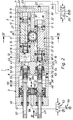
- the rotary drive device generally designated 1 in the drawing comprises a drive module 2 and a Detachably fixed to this positioning module 3.
- the Structure of the drive module 2 can be the prior art correspond, the actual innovation extends to the positioning module 3 and its interaction with the Drive module 2.
- the drive module 2 contains an elongated first housing 4 with expediently cuboidal outer contour.
- it comprises an elongated base section 5, which in Longitudinal direction of two piston receiving spaces arranged side by side is enforced.
- cover 7 Through one on the back the base section 5 attached cover 7 are the Piston receiving spaces 6, 6 'sealed at one axial end.
- the opposite front end causes the positioning module 3, which with its housing - hereinafter referred to as the second housing 8 - to the front end of the base section 5 and is attached by means of screws, not shown.
- each piston receiving space 6, 6 ' there is an in Drive piston 12 guided in the longitudinal direction, 12 '.
- Each drive piston 12, 12 ' has an in Rack-like toothing 13 extending in the longitudinal direction, 13 'with transverse and in particular at right angles to the longitudinal axes 14, 14 'of the piston receiving spaces 6, 6' extending Teeth.
- the teeth are 13, 13 'on rack elements 15, 15', the axially fixed on both sides with a piston head 16 each are the one associated with the inner surface of the Piston receiving space 6, 6 'cooperating annular Seal 17 carries.
- Each piston receiving space 6, 6 ' is by the one located therein Drive pistons 12, 12 'in two working spaces 18, 19; 18 ', 19' divided. Communicate via fluid channels 22 the working spaces with the outside of the first housing 4 in particular at the end cover 7 opening connection openings 23, via which a fluid pressure medium, in particular Compressed air can be supplied and removed as required can.
- the arrangement is preferably made so that the Positioning module 3 facing front working space 18, 18 ' of a respective piston receiving space 6, 6 'with the rear Working space 19 ', 19 of the other piston receiving space communicates, the communicating in pairs Workrooms a common connection opening 23rd can be assigned via the schematically indicated Pressure fluid lines 24 with a first control valve device 25 communicate.
- the first control valve device 25 of the exemplary embodiment is a 4/3-way valve carried out in the neutral position shown all work rooms 18, 19; 18 ', 19' to the surrounding area R vented. In the other two possible switching positions the working rooms are pressurized in this way or vented that the drive pistons 12, 12 ' in mutually parallel directions along the longitudinal axes 14, 14 'are moved synchronously in opposite directions. At leads a forward movement of the one drive piston so the other drive piston makes a backward movement.
- the area of the toothing 13, 13 ' Output section 28 is expedient on the outer circumference with a self-contained ring gear 34 and non-rotatably connected, which at the same time, diametrically opposite positions, with the two teeth 13, 13 'of the drive piston 12, 12' combs.
- Fasteners 35 allow the setting components to be rotated or pivoted, for example of a gripper used to handle workpieces.
- the drive module 2 is now in the form of the positioning module 3 assigned a position setting device, the by interaction with the two drive pistons 12, 12 ' the specification of a rotational intermediate position of the driven part 27 allows relative to the first housing 4, wherein the intermediate position lies between the end positions, the the output part 27 takes an angular position when the drive piston 12, 12 'one or the other of their two take possible axial end positions.
- end positions can be defined in particular in that the drive piston 12, 12 'on a cover-side contact surface get to the facility.
- the position setting device 3 has a stop unit axially upstream of the drive piston 12, 12 ' 36, which are indicated in a by double arrow Direction of displacement 37 parallel to the directions of travel the drive piston 12, 12 'relative to the aforementioned is relocatable. It is in the second housing 8 slidably mounted and has two in axial Extension of the two drive pistons 12, 12 'at a distance stop parts 38, 38 'arranged next to one another. Each stop part 38, 38 'has its associated one Piston receiving space 6, 6 'facing the end face via a stop surface 42, 42 ', which is a counter stop surface 43, 43 'axially opposite, which is located on the End face of the axially adjacent drive piston 12, 12 ' located.
- the stop unit 36 is through in the embodiment Fluid power between the basic position shown in Fig. 2 and one in this respect axially towards the drive module 2 shifted positioning position movable.
- the stop surfaces 42, 42 ' are outside the maximum possible axial travel of the drive pistons 12, 12 ', expediently in the second Housing 8 are retracted.
- the two stop parts 38, 38 ' project axially into the adjacent one Piston receiving space 6, 6 'in and take the in Fig. 2 indicated by the one stop part Position.
- This position 44 stands out characterized in that both stop parts 38, 38 'with their Stop surfaces 42, 42 'on the counter stop surface 43, 43' of the axially adjacent drive piston 12, 12 'simultaneously issue.
- the two are through the meshing engagement 13, 13 'motion-coupled with each other Drive piston 12, 12 'clamped axially immovable, and you get a play-free fixation of the Output part 27 in the present intermediate position.
- the in the exemplary embodiment in the positioning position present intermediate position of the driven part 27 is one Middle position, the angular middle between the two End positions. 5 shows this for clarification and 6 the in the basic position of the stop unit 36 realizable end positions, between those in the embodiment there is an angle of rotation of 90 °.
- Fig. 7 is the same arrangement when shifted to the positioning position Stop unit 36 shown, the driven part 27 occupies a 45 ° center position.
- the stop unit 36 is for its actuation in the exemplary embodiment equipped with an actuating piston 45, which is formed in a second housing 8 another piston receiving space 46 is located in Direction of displacement 37 is displaceable.
- the actuating piston 45 is elongated Outline designed as a flat piston, of cross section seen an elongated shape. In the embodiment 3 it has flat longitudinal sides which are connected to each other via rounded narrow sides. An oval and, for example, elliptical contour would also be conceivable.
- the two stop parts 38, 38 'are plunger-like formed, being in coaxial extension of the each associated drive piston 12, 12 'with the Actuating piston 45 are connected.
- the connection areas are in the embodiment in the range Narrow-side sections of the actuating piston 45.
- the positioning module 3 is of the single-acting type Working cylinder built, the rear working space 55 is constantly vented via a housing channel 56.
- the one on the other side of the actuating piston 45 lying front work space 57 communicates via a connection opening 58 passing through the second housing 8 and a pressure medium line 62 connected to it a second control valve device 63.
- the front working space 57 optionally with a pressure medium source P connects or vented to the environment R.
- position module 3 also according to Art a double-acting cylinder can, regardless of the actuation state of the drive module 2 the return movement of the stop unit 36 in the To be able to make the basic position.
- the two stop surfaces in the embodiment 42, 42 ' provided on two stop elements 65, each on a tubular body 66 of the Stop unit 36 are mounted so adjustable that they move in the direction of travel of the drive pistons 12, 12 ' can be adjusted continuously.
- the stop elements are preferably 65 bolt-like design and with one Provide external thread, through which they are formed in the tube type Base body 66 are screwed.
- This tubular Base body 66 is in one piece in the exemplary embodiment formed with the bearing rod 47, which is hollow is, so that the stop part 38, 38 'and the associated bearing rod 47, 47 'through access channel 67 results from the outside of the second housing 8 access to the associated stop element 65 enables.
- the rotary drive device 1 allows in the embodiment a simple capture of the set Intermediate position via the position setting device 3.
- the position setting device can be 3 optionally to different Apply drive modules 2 and in particular also enables retrofitting conventional drive modules.
Landscapes
- Engineering & Computer Science (AREA)
- Mechanical Engineering (AREA)
- General Engineering & Computer Science (AREA)
- Chemical & Material Sciences (AREA)
- Physics & Mathematics (AREA)
- Fluid Mechanics (AREA)
- Combustion & Propulsion (AREA)
- Analytical Chemistry (AREA)
- Actuator (AREA)
Abstract
Description
- Fig. 1
- eine bevorzugte Bauform der erfindungsgemäßen Drehantriebsvorrichtung in perspektivischer Darstellung,
- Fig. 2
- einen Längsschnitt durch die Drehantriebsvorrichtung gemäß Schnittlinie II-II aus Fig. 1 und 4,
- Fig. 3
- eine Stirnansicht der Drehantriebsvorrichtung mit Blick gemäß Pfeil III aus Fig. 2,
- Fig. 4
- einen Querschnitt durch die Drehantriebsvorrichtung gemäß Schnittlinie IV-IV aus Fig. 2 und
- Fig. 5 bis 7
- in schematischer Darstellung verschiedene Betriebszustände der Drehantriebsvorrichtung.
Claims (19)
- Fluidbetätigte Drehantriebsvorrichtung, mit einem drehbar gelagerten Abtriebsteil (27), das wenigstens einen Zahnkranz (34) aufweist, mit dem an zwei nebeneinanderliegend angeordneten Antriebskolben (12, 12') vorgesehene zahnstangenartige Verzahnungen (13, 13') in Eingriff stehen, wobei die Antriebskolben (12, 12') durch Fluidbeaufschlagung in zueinander parallelen Richtungen gegensinnig bewegbar sind, um eine Drehbewegung (26) des Abtriebsteils (27) zwischen zwei Endpositionen hervorzurufen, gekennzeichnet durch eine Positionsvorgabeeinrichtung (3), die durch Zusammenwirken mit den beiden Antriebskolben (12, 12') die Vorgabe einer zwischen den Endpositionen befindlichen Zwischenposition des Abtriebsteils (27) ermöglicht und hierzu über eine zwei in axialer Verlängerung der beiden Antriebskolben (12, 12') nebeneinanderliegend angeordnete Anschlagteile (38, 38') aufweisende Anschlageinheit (36) verfügt, die relativ zu den Antriebskolben (12, 12') in eine Positionierstellung verlagerbar ist, in der die beiden Anschlagteile (38, 38') gleichzeitig am jeweils zugeordneten Antriebskolben (12, 12') anliegen.
- Drehantriebsvorrichtung nach Anspruch 1, dadurch gekennzeichnet, daß die beiden Anschlagteile (38, 38') in der Positionierstellung an einer axial gerichteten Stirnfläche (43, 43') des jeweils zugeordneten Antriebskolbens (12, 12') anliegen.
- Drehantriebsvorrichtung nach Anspruch 1 oder 2, dadurch gekennzeichnet, daß die Anschlageinheit (36) in der Positionierstellung mit beiden Anschlagteilen (38, 38') axial in den den zugeordneten Antriebskolben (12, 12') verschiebbar aufnehmenden Kolbenaufnahmeraum (6, 6') hineinragt.
- Drehantriebsvorrichtung nach einem der Ansprüche 1 bis 3, dadurch gekennzeichnet, daß die Anschlageinheit (36) zwischen der Positionierstellung und einer außerhalb des maximal möglichen axialen Verfahrweges der Antriebskolben (12, 12') liegenden Grundstellung verlagerbar ist.
- Drehantriebsvorrichtung nach einem der Ansprüche 1 bis 4, dadurch gekennzeichnet, daß die Verlagerungsrichtung (37) der Anschlageinheit (36) parallel zu den Verfahrrichtungen der Antriebskolben (12, 12') verläuft.
- Drehantriebsvorrichtung nach einem der Ansprüche 1 bis 5, dadurch gekennzeichnet, daß die Anschlageinheit (36) den Antriebskolben (12, 12') axial vorgelagert ist.
- Drehantriebsvorrichtung nach einem der Ansprüche 1 bis 6, dadurch gekennzeichnet, daß die Anschlageinheit (36) durch Fluidkraft verlagerbar ist.
- Drehantriebsvorrichtung nach einem der Ansprüche 1 bis 7, dadurch gekennzeichnet, daß die Anschlageinheit (36) über einen fest mit den beiden Anschlagteilen (38, 38') verbundenen, fluidbeaufschlagbaren Betätigungskolben (45) verfügt.
- Drehantriebsvorrichtung nach Anspruch 8, dadurch gekennzeichnet, daß der Betätigungskolben (45) im Querschnitt gesehen einen länglichen Umriß aufweist.
- Drehantriebsvorrichtung nach Anspruch 9, dadurch gekennzeichnet, daß die beiden Anschlagteile (38, 38') im Bereich der schmalseitigen Randabschnitte des Betätigungskolbens (45) vorgesehen sind.
- Drehantriebsvorrichtung nach einem der Ansprüche 1 bis 10, dadurch gekennzeichnet, daß die Anschlagteile (38, 38') stößelartig ausgebildet sind und in insbesondere koaxialer Verlängerung des jeweils zugeordneten Antriebskolbens (12, 12') angeordnet sind.
- Drehantriebsvorrichtung nach Anspruch 11, dadurch gekennzeichnet, daß die Anschlageinheit (36) über zwei in koaxialer Verlängerung der Anschlagteile (38, 38') angeordnete Lagerstangen (47, 47') verfügt.
- Drehantriebsvorrichtung nach einem der Ansprüche 1 bis 12, dadurch gekennzeichnet, daß mindestens eines der Anschlagteile (38, 38') über ein die mit dem zugeordneten Antriebskolben (12, 12') zusammenarbeitende Anschlagfläche (42, 42') tragendes Anschlagelement (65) verfügt, das relativ zu einem es tragenden Grundkörper (66) der Anschlageinheit (36) in Verfahrrichtung des zugeordneten Antriebskolbens (12, 12') verstellbar ist.
- Drehantriebsvorrichtung nach Anspruch 13, dadurch gekennzeichnet, daß das Verstellen des Anschlagelementes (65) durch einen Hohlraum (67) des Grundkörpers (66) hindurch erfolgt.
- Drehantriebsvorrichtung nach einem der Ansprüche 1 bis 14, dadurch gekennzeichnet, daß die Anschlageinheit (36) wenigstens ein mit einem Positionssensor (72) zusammenarbeitendes Betätigungsglied (73) trägt.
- Drehantriebsvorrichtung nach einem der Ansprüche 1 bis 15, dadurch gekennzeichnet, daß die beiden Antriebskolben (12, 12') beim Verlagern der Anschlageinheit (36) in die Positionierstellung fluidisch unbeaufschlagt sind und von der Anschlageinheit (36) verschoben werden.
- Drehantriebsvorrichtung nach einem der Ansprüche 1 bis 16, gekennzeichnet durch eine beim Verlassen der Positionierstellung der Anschlageinheit (36) wirksame Abluftdrosselung (64).
- Drehantriebsvorrichtung nach einem der Ansprüche 1 bis 17, dadurch gekennzeichnet, daß die Antriebskolben (12, 12') und die Anschlageinheit (36) in separaten, stirnseitig aneinandergesetzten Gehäusen (4, 8) angeordnet sind.
- Drehantriebsvorrichtung nach einem der Ansprüche 1 bis 18, dadurch gekennzeichnet, daß die vorgegebene Zwischenposition eine Mittenposition mittig zwischen den beiden Endpositionen des Abtriebsteils (27) ist.
Applications Claiming Priority (2)
| Application Number | Priority Date | Filing Date | Title |
|---|---|---|---|
| DE19803819 | 1998-01-31 | ||
| DE19803819A DE19803819B4 (de) | 1998-01-31 | 1998-01-31 | Fluidbetätigte Drehantriebsvorrichtung |
Publications (3)
| Publication Number | Publication Date |
|---|---|
| EP0933527A2 true EP0933527A2 (de) | 1999-08-04 |
| EP0933527A3 EP0933527A3 (de) | 2001-12-05 |
| EP0933527B1 EP0933527B1 (de) | 2004-02-04 |
Family
ID=7856271
Family Applications (1)
| Application Number | Title | Priority Date | Filing Date |
|---|---|---|---|
| EP98123579A Expired - Lifetime EP0933527B1 (de) | 1998-01-31 | 1998-12-10 | Fluidbetätigte Drehantriebsvorrichtung |
Country Status (4)
| Country | Link |
|---|---|
| US (1) | US6170384B1 (de) |
| EP (1) | EP0933527B1 (de) |
| JP (1) | JP3122423B2 (de) |
| DE (2) | DE19803819B4 (de) |
Cited By (2)
| Publication number | Priority date | Publication date | Assignee | Title |
|---|---|---|---|---|
| DE10114480C2 (de) * | 2000-04-12 | 2003-12-18 | Smc Corp | Schwenkstellglied mit drei Haltepositionen |
| DE10249509A1 (de) * | 2002-10-23 | 2004-05-13 | Bar Pneumatische Steuerungssysteme Gmbh | Pneumatischer Stellantrieb |
Families Citing this family (14)
| Publication number | Priority date | Publication date | Assignee | Title |
|---|---|---|---|---|
| JP3701576B2 (ja) * | 2001-04-10 | 2005-09-28 | Smc株式会社 | ダブルラック・ピニオン式揺動装置 |
| US6708489B2 (en) | 2001-08-03 | 2004-03-23 | Parker & Harper Companies, Inc. | Pneumatic actuator |
| DE102007017418B4 (de) | 2007-04-13 | 2010-04-01 | Festo Ag & Co. Kg | Fluidbetätigte Drehantriebsvorrichtung |
| DE102009011764A1 (de) * | 2009-03-04 | 2010-09-09 | Festo Ag & Co. Kg | Drehantriebsvorrichtung |
| EP2420682B1 (de) | 2010-08-21 | 2012-06-06 | FESTO AG & Co. KG | Fluidbetätigte Drehantriebsvorrichtung |
| EP2495449B1 (de) * | 2011-03-01 | 2013-04-03 | FESTO AG & Co. KG | Fluidbetätigte Drehantriebsvorrichtung |
| EP2495450B1 (de) | 2011-03-01 | 2013-05-15 | FESTO AG & Co. KG | Fluidbetätigte Drehantriebsvorrichtung |
| EP2495451B1 (de) | 2011-03-01 | 2013-05-15 | FESTO AG & Co. KG | Fluidbetätigte Drehantriebsvorrichtung |
| EP2503162A1 (de) | 2011-03-25 | 2012-09-26 | Festo AG & Co. KG | Fluidbetätigte Drehantriebsvorrichtung |
| USD674423S1 (en) | 2012-02-14 | 2013-01-15 | Festo Ag & Co. Kg | Rotary drive device |
| US9586676B2 (en) * | 2014-04-01 | 2017-03-07 | The Boeing Company | Pneumatic positioning system |
| JP1575546S (de) * | 2016-12-16 | 2017-05-08 | ||
| JP1575545S (de) * | 2016-12-16 | 2017-05-08 | ||
| JP1575966S (de) * | 2016-12-16 | 2017-05-08 |
Family Cites Families (14)
| Publication number | Priority date | Publication date | Assignee | Title |
|---|---|---|---|---|
| FR972346A (fr) * | 1941-02-10 | 1951-01-29 | Camions Bernard | Dispositif pour commandes positives à distance par fluides sous pression |
| US3019771A (en) * | 1960-06-09 | 1962-02-06 | Gen Dynamics Corp | Hydraulic rotary actuator |
| US3190190A (en) * | 1963-05-02 | 1965-06-22 | Flo Tork Inc | Rotary actuator |
| US3958493A (en) * | 1973-08-20 | 1976-05-25 | Tokico Ltd. | Multiple-stage actuating device |
| GB2138505B (en) * | 1983-04-23 | 1986-09-10 | Duncan Ross Stewart | Fluid-pressure-operated actuators |
| JPS6319408A (ja) | 1986-07-07 | 1988-01-27 | Akita Kikai Sekkei:Kk | 回転駆動機 |
| DE3741261A1 (de) * | 1987-01-10 | 1988-07-28 | Amg Antrieb Mechanik Gmbh | Schwenkantrieb mit rueckstelleinheit |
| JPH0260704A (ja) | 1988-08-26 | 1990-03-01 | Matsushita Electric Works Ltd | 改質木材の製法 |
| JPH03121201A (ja) | 1989-10-05 | 1991-05-23 | Mitsubishi Heavy Ind Ltd | スクロール部材の製造方法 |
| EP0449803A1 (de) * | 1990-03-28 | 1991-10-02 | Hoerbiger Fluidtechnik Kg | Schwenkantrieb |
| JPH04101809A (ja) | 1990-08-22 | 1992-04-03 | Yu Hirayama | 窯業製品の成形方法 |
| JPH05223106A (ja) | 1991-06-05 | 1993-08-31 | Koganei:Kk | ロータリアクチュエータ |
| JP3121201B2 (ja) | 1994-04-28 | 2000-12-25 | 象印マホービン株式会社 | 自動製パン機 |
| JP3121201U (ja) | 2006-02-15 | 2006-04-27 | 卓司 扇谷 | ピン刺し機 |
-
1998
- 1998-01-31 DE DE19803819A patent/DE19803819B4/de not_active Expired - Fee Related
- 1998-12-10 EP EP98123579A patent/EP0933527B1/de not_active Expired - Lifetime
- 1998-12-10 DE DE59810712T patent/DE59810712D1/de not_active Expired - Lifetime
-
1999
- 1999-01-13 US US09/229,791 patent/US6170384B1/en not_active Expired - Lifetime
- 1999-02-01 JP JP11024228A patent/JP3122423B2/ja not_active Expired - Fee Related
Non-Patent Citations (1)
| Title |
|---|
| None |
Cited By (2)
| Publication number | Priority date | Publication date | Assignee | Title |
|---|---|---|---|---|
| DE10114480C2 (de) * | 2000-04-12 | 2003-12-18 | Smc Corp | Schwenkstellglied mit drei Haltepositionen |
| DE10249509A1 (de) * | 2002-10-23 | 2004-05-13 | Bar Pneumatische Steuerungssysteme Gmbh | Pneumatischer Stellantrieb |
Also Published As
| Publication number | Publication date |
|---|---|
| EP0933527A3 (de) | 2001-12-05 |
| JPH11270508A (ja) | 1999-10-05 |
| EP0933527B1 (de) | 2004-02-04 |
| DE19803819B4 (de) | 2004-05-13 |
| JP3122423B2 (ja) | 2001-01-09 |
| DE19803819A1 (de) | 1999-08-12 |
| US6170384B1 (en) | 2001-01-09 |
| DE59810712D1 (de) | 2004-03-11 |
Similar Documents
| Publication | Publication Date | Title |
|---|---|---|
| EP0933527B1 (de) | Fluidbetätigte Drehantriebsvorrichtung | |
| EP1272409B1 (de) | Handhabungsgerät zum umpositionieren von teilen | |
| DE10328934A1 (de) | Motorischer Antrieb für chirurgische Instrumente | |
| EP1350606A1 (de) | Fluidbetätigter Greifer | |
| EP1350960B1 (de) | Fluidbetätigte Antriebsvorrichtung | |
| EP0911530B1 (de) | Dreh-Linear-Einheit | |
| DE3032554C2 (de) | ||
| EP2495449B1 (de) | Fluidbetätigte Drehantriebsvorrichtung | |
| DE2265348B2 (de) | Druckmittelbetriebener Servomotor | |
| EP1429037B1 (de) | Fluidbetätigter Dreistellungs-Drehantrieb | |
| EP2420682B1 (de) | Fluidbetätigte Drehantriebsvorrichtung | |
| DE3627918C2 (de) | ||
| EP2503162A1 (de) | Fluidbetätigte Drehantriebsvorrichtung | |
| DE19508190A1 (de) | Hydraulische Antriebseinheit | |
| DE102019208886B4 (de) | Drehantriebsvorrichtung | |
| EP1073556B1 (de) | Radialpresse | |
| DE102021200980B4 (de) | Linearantriebsvorrichtung | |
| DE1918746A1 (de) | Transfereinrichtung | |
| DE3811110A1 (de) | Kolbenantrieb | |
| DE3632355A1 (de) | Druckmittelbetaetigter vielstellungszylinder | |
| EP1703144B1 (de) | Fluidbetätigter Linearantrieb | |
| EP2448712B1 (de) | Arbeitsvorrichtung mit mindestens einer antriebseinheit | |
| DE19934279B4 (de) | Positionsvorgabeeinrichtung | |
| EP0279837A1 (de) | Hydraulisches nachlauf-regelventil. | |
| EP3817901B1 (de) | Kopplungsvorrichtung |
Legal Events
| Date | Code | Title | Description |
|---|---|---|---|
| PUAI | Public reference made under article 153(3) epc to a published international application that has entered the european phase |
Free format text: ORIGINAL CODE: 0009012 |
|
| AK | Designated contracting states |
Kind code of ref document: A2 Designated state(s): AT BE CH CY DE DK ES FI FR GB GR IE IT LI LU MC NL PT SE Kind code of ref document: A2 Designated state(s): DE FI FR GB IT |
|
| AX | Request for extension of the european patent |
Free format text: AL;LT;LV;MK;RO;SI |
|
| PUAL | Search report despatched |
Free format text: ORIGINAL CODE: 0009013 |
|
| AK | Designated contracting states |
Kind code of ref document: A3 Designated state(s): AT BE CH CY DE DK ES FI FR GB GR IE IT LI LU MC NL PT SE |
|
| AX | Request for extension of the european patent |
Free format text: AL;LT;LV;MK;RO;SI |
|
| 17P | Request for examination filed |
Effective date: 20011121 |
|
| AKX | Designation fees paid |
Free format text: DE FI FR GB IT |
|
| 17Q | First examination report despatched |
Effective date: 20021205 |
|
| GRAP | Despatch of communication of intention to grant a patent |
Free format text: ORIGINAL CODE: EPIDOSNIGR1 |
|
| GRAS | Grant fee paid |
Free format text: ORIGINAL CODE: EPIDOSNIGR3 |
|
| GRAA | (expected) grant |
Free format text: ORIGINAL CODE: 0009210 |
|
| AK | Designated contracting states |
Kind code of ref document: B1 Designated state(s): DE FI FR GB IT |
|
| REG | Reference to a national code |
Ref country code: GB Ref legal event code: FG4D Free format text: NOT ENGLISH |
|
| GBT | Gb: translation of ep patent filed (gb section 77(6)(a)/1977) |
Effective date: 20040204 |
|
| REG | Reference to a national code |
Ref country code: IE Ref legal event code: FG4D Free format text: GERMAN |
|
| REF | Corresponds to: |
Ref document number: 59810712 Country of ref document: DE Date of ref document: 20040311 Kind code of ref document: P |
|
| REG | Reference to a national code |
Ref country code: IE Ref legal event code: FD4D |
|
| ET | Fr: translation filed | ||
| PLBE | No opposition filed within time limit |
Free format text: ORIGINAL CODE: 0009261 |
|
| STAA | Information on the status of an ep patent application or granted ep patent |
Free format text: STATUS: NO OPPOSITION FILED WITHIN TIME LIMIT |
|
| 26N | No opposition filed |
Effective date: 20041105 |
|
| PGFP | Annual fee paid to national office [announced via postgrant information from national office to epo] |
Ref country code: FI Payment date: 20061207 Year of fee payment: 9 |
|
| PG25 | Lapsed in a contracting state [announced via postgrant information from national office to epo] |
Ref country code: FI Free format text: LAPSE BECAUSE OF NON-PAYMENT OF DUE FEES Effective date: 20071210 |
|
| REG | Reference to a national code |
Ref country code: FR Ref legal event code: PLFP Year of fee payment: 18 |
|
| PGFP | Annual fee paid to national office [announced via postgrant information from national office to epo] |
Ref country code: GB Payment date: 20151116 Year of fee payment: 18 |
|
| PGFP | Annual fee paid to national office [announced via postgrant information from national office to epo] |
Ref country code: FR Payment date: 20151218 Year of fee payment: 18 |
|
| PGFP | Annual fee paid to national office [announced via postgrant information from national office to epo] |
Ref country code: IT Payment date: 20151222 Year of fee payment: 18 |
|
| PGFP | Annual fee paid to national office [announced via postgrant information from national office to epo] |
Ref country code: DE Payment date: 20161117 Year of fee payment: 19 |
|
| GBPC | Gb: european patent ceased through non-payment of renewal fee |
Effective date: 20161210 |
|
| REG | Reference to a national code |
Ref country code: FR Ref legal event code: ST Effective date: 20170831 |
|
| PG25 | Lapsed in a contracting state [announced via postgrant information from national office to epo] |
Ref country code: IT Free format text: LAPSE BECAUSE OF NON-PAYMENT OF DUE FEES Effective date: 20161210 Ref country code: FR Free format text: LAPSE BECAUSE OF NON-PAYMENT OF DUE FEES Effective date: 20170102 |
|
| PG25 | Lapsed in a contracting state [announced via postgrant information from national office to epo] |
Ref country code: GB Free format text: LAPSE BECAUSE OF NON-PAYMENT OF DUE FEES Effective date: 20161210 |
|
| REG | Reference to a national code |
Ref country code: DE Ref legal event code: R119 Ref document number: 59810712 Country of ref document: DE |
|
| PG25 | Lapsed in a contracting state [announced via postgrant information from national office to epo] |
Ref country code: DE Free format text: LAPSE BECAUSE OF NON-PAYMENT OF DUE FEES Effective date: 20180703 |