EP0933889A1 - Vorrichtung zum Senden und Vorrichtung zum Empfangen digitaler Tonsignale - Google Patents
Vorrichtung zum Senden und Vorrichtung zum Empfangen digitaler Tonsignale Download PDFInfo
- Publication number
- EP0933889A1 EP0933889A1 EP99101205A EP99101205A EP0933889A1 EP 0933889 A1 EP0933889 A1 EP 0933889A1 EP 99101205 A EP99101205 A EP 99101205A EP 99101205 A EP99101205 A EP 99101205A EP 0933889 A1 EP0933889 A1 EP 0933889A1
- Authority
- EP
- European Patent Office
- Prior art keywords
- frequency
- sound signal
- digital sound
- data
- frequency band
- Prior art date
- Legal status (The legal status is an assumption and is not a legal conclusion. Google has not performed a legal analysis and makes no representation as to the accuracy of the status listed.)
- Withdrawn
Links
- 230000005236 sound signal Effects 0.000 title claims abstract description 168
- 238000005070 sampling Methods 0.000 claims abstract description 223
- 238000007906 compression Methods 0.000 claims abstract description 103
- 230000006835 compression Effects 0.000 claims abstract description 103
- 230000003044 adaptive effect Effects 0.000 claims abstract description 69
- 238000001914 filtration Methods 0.000 claims abstract description 11
- 230000006837 decompression Effects 0.000 claims description 20
- 238000000034 method Methods 0.000 description 29
- 238000010586 diagram Methods 0.000 description 14
- 238000004458 analytical method Methods 0.000 description 11
- 230000015572 biosynthetic process Effects 0.000 description 9
- 238000003786 synthesis reaction Methods 0.000 description 9
- 238000004148 unit process Methods 0.000 description 9
- 238000001514 detection method Methods 0.000 description 8
- 230000005540 biological transmission Effects 0.000 description 6
- 238000006243 chemical reaction Methods 0.000 description 6
- 239000000284 extract Substances 0.000 description 5
- 238000001228 spectrum Methods 0.000 description 5
- 230000000007 visual effect Effects 0.000 description 4
- 230000003321 amplification Effects 0.000 description 2
- 238000013528 artificial neural network Methods 0.000 description 2
- 238000004364 calculation method Methods 0.000 description 2
- 238000004519 manufacturing process Methods 0.000 description 2
- 239000011159 matrix material Substances 0.000 description 2
- 238000003199 nucleic acid amplification method Methods 0.000 description 2
- 238000012952 Resampling Methods 0.000 description 1
- 238000007796 conventional method Methods 0.000 description 1
- 238000013144 data compression Methods 0.000 description 1
- 230000001934 delay Effects 0.000 description 1
- 210000005069 ears Anatomy 0.000 description 1
- 238000000605 extraction Methods 0.000 description 1
- 230000006870 function Effects 0.000 description 1
- 239000003550 marker Substances 0.000 description 1
- 230000002123 temporal effect Effects 0.000 description 1
Images


Classifications
-
- H—ELECTRICITY
- H04—ELECTRIC COMMUNICATION TECHNIQUE
- H04B—TRANSMISSION
- H04B14/00—Transmission systems not characterised by the medium used for transmission
- H04B14/02—Transmission systems not characterised by the medium used for transmission characterised by the use of pulse modulation
- H04B14/04—Transmission systems not characterised by the medium used for transmission characterised by the use of pulse modulation using pulse code modulation
- H04B14/046—Systems or methods for reducing noise or bandwidth
Definitions
- This invention relates to a digital sound signal transmitting apparatus for performing compression encoding on a digitized sound signal, and then transmitting the resultant encoded data via a predetermined medium, and a digital sound signal receiving apparatus for receiving data including the encoded data output from the transmitting apparatus, and then performing decompression decoding corresponding to the compression encoding.
- digital sound signal transmitting apparatuses and receiving apparatuses There are known various types of conventional digital sound signal transmitting apparatuses and receiving apparatuses. These digital sound signal transmitting apparatuses and receiving apparatuses include magnetic recording/reproducing apparatuses, data transmitting/receiving apparatuses, encoded-image recording apparatuses capable of recording data, by printing, on a printing/recording medium in the form of an optically readable encoded image, and reading apparatuses for reading the recorded data. Those apparatuses employ various types of compression encoding methods to save the amount of data to be transmitted and received or to realize high speed transmission.
- a sound band corresponding to the reproduction quality is set for the sound and compression encoding of a high compression ratio and high quality is performed on the sound before transmitting it.
- the band of the to-be-transmitted sound is actually fixed.
- Japanese Patent Application KOKAI Publication No. 61-43796 proposes a single apparatus equipped with a plurality of compression encoding means for performing different compression encoding processes.
- this apparatus an optimal one is selected from the plurality of compression encoding means in accordance with the type of a sound or a request from the user, in order to transmit and receive digitised sound signals.
- Japanese Patent Application KOKAI Publication No. 5-335968 proposes an apparatus, in which a clock signal is directly extracted from to-be-transmitted digital data, the frequency of the extracted clock signal is converted into a low sampling frequency, the digital data is encoded on the basis of the converted sampling frequency, and the resultant encoded data is transmitted.
- This publication does not refer to the number of data samples for encoding by the encoding means.
- the invention has been developed under the above-described circumstances, and is aimed at providing a digital sound signal transmitting apparatus and receiving apparatus which each employ only a single compression encoding means but can enhance either the quality of to-be-transmitted and to-be-received digital sound signals, or the compression ratios of them in accordance with the purpose, and wherein an increase in size and manufacturing cost is minimized.
- a digital sound signal transmitting apparatus for compression encoding a digitized sound signal into encoded data, and transmitting the encoded data via a predetermined medium, comprising:
- a digital sound signal receiving apparatus for receiving data which contains encoded data transmitted from a digital sound signal transmitting apparatus including: a frequency band setting unit for setting a frequency band for a to-be-transmitted digital sound signal, and determining a cut-off frequency and a re-sampling frequency for the digital sound signal on the basis of the set frequency band; an adaptive band limiting filter for adaptively filtering the to-be-transmitted digital sound signal on the basis of the cut-off frequency determined by the frequency band setting unit; a re-sampling unit for re-sampling the digital sound signal having passed through the adaptive band limiting filter, using the re-sampling frequency determined by the frequency band setting unit; and a compression encoding unit for compression encoding the digital sound signal re-sampled by the re-sampling unit, in units of a predetermined number of data samples, thereby creating encoded data,
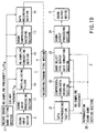
- FIG. 1 shows a digital sound signal transmitting apparatus 1 and receiving apparatus 2 according to a first embodiment of the invention.
- the transmitting apparatus 1 comprises a sound input processing section 11, a band adaptive type input data converting section 12, a sound compression encoding section 13 and a data recording section 14.
- the receiving apparatus 2 comprises a data reproducing section 21, a compressed-sound-data decoding section 22, a band adaptive type output data converting section 23 and a sound output processing section 24.
- a sound signal from a sound input device 3 such as a microphone, an external audio machine, etc. is input to the sound input processing section 11, where the signal is digitized.
- the digitized sound data is input to the band adaptive type input data converting section 12, where the band component of the input sound data is analyzed, i.e. it is analyzed which band component is contained in the input sound data, thereby determining a re-sampling frequency on the basis of the analysis result and re-sampling the input sound data using the re-sampling frequency.
- the re-sampling frequency is also sent to the sound compression encoding section 13 and the data recording section 14, which are located downstream of the section 12.
- the re-sampled sound data is input to the sound compression encoding section 13, where it is subjected to compression encoding in units of a predetermined number of data samples.
- the compression-encoded sound data is input to the data recording section 14, where it is recorded on a recording/transmitting medium 4.
- the re-sampling frequency for example, is additionally recorded as a header.
- a data reproducing section 21 reproduces the encoded sound data recorded on the recording/transmitting medium 4, and extracts the re-sampling frequency from the header.
- the extracted re-sampling frequency is input to the compressed-sound-data decoding section 22 and the band adaptive type output data converting section 23, which are located downstream of the section 21.
- the reproduced encoded sound data is input to the compressed-sound-data decoding section 22.
- the input encoded sound data is decoded by decompression.
- the decoded data is input to the band adaptive type output data converting section 23, where necessary up-sampling is performed on the basis of the re-sampling frequency, thereby supplying the resultant sound data to the sound output processing section 24.
- the sound output processing section 24 subjects the input sound data to D/A conversion, filtering or amplification, and outputs a sound corresponding to the input sound data through a sound output device 5 such as a speaker, an earphone, a headphone, etc.
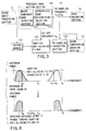
- the sound input processing section 11 is constituted of, for example, a pre-amplifier 111, an LPF 112, a sample and hold and A/D converter (hereinafter referred to as an "S/H & ADC") 113, an input sampling clock generating section 114 and a sampling frequency converting section 115.
- a pre-amplifier 111 an LPF 112
- a sample and hold and A/D converter hereinafter referred to as an "S/H & ADC”
- S/H & ADC sample and hold and A/D converter
- An analog sound signal input through the sound input device 3 is amplified by the pre-amplifier 111. Then, the frequency component of the amplified signal, which is not less than a cut-off frequency f s , is cut off by the LPF 112, and the resultant signal is input to the S/H & ADC 113.
- the S/H & ADC 113 is supplied with a sampling clock signal from the input sampling clock generating section 114.
- the S/H & ADC 113 samples an analog sound signal from the LPF 112 on the basis of the sampling clock signal, and converts the sampling result to a digital value.
- the thus-obtained digital sound data is supplied to the band adaptive type input data converting section 12.
- the frequency f a of the sampling clock signal supplied from the input sampling clock generating section 114 is set at a value not less than twice the cut-off frequency f s used in the LPF 112 in order to satisfy the Nyquist's sampling theorem.
- the cut-off frequency f s of the LPF 112 is pre-set as the maximum frequency of a maximum guarantee band which should be secured by the transmitting apparatus 1. In the case of a transmitting apparatus whose target frequency band is, for example, 8 kHz, 4 kHz or 2 kHz, the cut-off frequency f s of 8 kHz. Accordingly, the sampling clock frequency f a is set at 16 kHz or more.
- the sampling frequency converting section 115 converts the sampling frequency to a value corresponding to the transmitting apparatus 1, and supplies the converted value to the band adaptive type input data converting section 12. In other words, sampling frequency conversion is performed when necessary since there are digital sound output devices 3' in which a rather high sampling frequency is set.
- the band adaptive type input data converting section 12 supplied with digital sound data from the S/H & ADC 113 and the sampling frequency converting section 115 comprises, as shown in, for example, FIG. 3, a frequency band setting section 121, a buffer memory 122, an adaptive anti-aliasing filter 123 and a re-sampling converting section 124.
- the frequency band setting section 121 includes a major component band detecting section 1211 and an appropriate band determining/selecting section 1212.
- the input digital sound data is supplied to the major component band detecting section 1211, where its major frequency band is detected, i.e. it is detected in which band the greatest number of frequency components exist, as will be described later in detail.
- the appropriate band determining/selecting section 1212 determines an appropriate band on the basis of the detection result, and sets a cut-off frequency f w and a re-sampling frequency f v .
- the cut-off frequency f w is obtained by multiplying, by an integer, a re-sampling basic frequency f 0 which is 1/n (n: integer) of the aforementioned maximum frequency f s of the maximum guarantee band.
- the appropriate band determining/selecting section 1212 stores a plurality of candidate values for the cut-off frequency obtained by multiplying, by an integer, the re-sampling basic frequency f 0 , and sets one of the candidate values as the cut-off frequency f w on the basis of the detection result of the major component band detecting section 1211.
- the appropriate band determining/selecting section 1212 stores cut-off frequency candidates of 2 kHz, 4 kHz, 6 kHz and 8 kHz. If the major component band detecting section 1211 detects that the band up to 4 kHz is the major band of the input digital sound data, and that almost no major frequency components exist in a frequency band higher than that, i.e. between 4 kHz and 8 kHz, the appropriate band determining/selecting section 1212 determines that the band up to 4 kHz is an appropriate one, and sets the cut-off frequency f w at 4 kHz.
- the re-sampling frequency f v should be twice or more the cut-off frequency f w , it is set at twice in this embodiment to minimize the amount of data processed in such an intermediate processing stage as above.
- the set cut-off frequency f w and re-sampling frequency f v are input to the adaptive anti-aliasing filter 123 and the re-sampling converting section 124, respectively. Moreover, as described above, the re-sampling frequency f v is input to the data recording section 14 and written into the header section of data. This frequency f v is also input to the sound compression encoding section 13 and used to generate a timing signal corresponding to a process unit for sound compression encoding performed in a real-time manner.
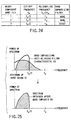
- the digital sound data stored in the buffer memory 122 is input to the adaptive anti-aliasing filter 123, thereby filtering the data using the cut-off frequency f w so as to prevent reflected noise. More specifically, as shown in the upper portion of FIG. 4, the spectrum 61 of an input sound is filtered by a filter which has an adaptive anti-aliasing filter characteristic 62 determined based on the cut-off frequency f w , thereby obtaining sound data with a spectrum 63 as shown in the lower portion of FIG. 4.
- the sound data having passed through the adaptive anti-aliasing filter 123 is input to the re-sampling converting section 124, whereby it is again re-sampled using the re-sampling frequency f v .
- the re-sampled data is supplied to the sound compression encoding section 13.
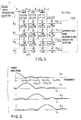
- the major component band detecting section 1211 can be formed of, for example, three delay elements 12111A - 12111C, ten adders 12112A - 12112J and six subtracters 12113A - 12113F, as is shown in FIG. 5.
- X i from the sound input processing section 11 X i-2 from the delay element 12111A, X i-4 from the delay element 12111B and X i-6 from the delay element 12111C are multiplied by +1, +1, +1 and +1, respectively, and then added to each other, using the four adders 12112A - 12112D.
- X i , X i-2 , X i-4 and X i-6 are multiplied by -1, -1, +1 and +1, respectively, and then added to each other, using the subtracters 12113A and 12113B and the adders 12112E and 12112F.
- X i , X i-2 , X i-4 and X i-6 are multiplied by -1, +1, +1 and -1, respectively, and then added to each other, using the subtracter 12113C, the adders 12112G and 12112H and the subtracter 12113D.
- X i , X i-2 , X i-4 and X i-6 are multiplied by +1, -1, +1 and -1, respectively, and then added to each other, using the adder 12112I, the subtracter 12113E, the adder 12112J and the subtracter 12113F.
- the major component band detecting section 1211 is not limited to a structure as described above for performing Hadamard transform, but may have any structure which realizes orthogonal transform suitable for frequency analysis, such as discrete Fourier transform, discrete cosine transform, etc.
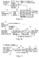
- the appropriate band determining/selecting section 1212 which receives the outputs [b 0 ] i - [b 3 ] i of the major component band detecting section 1211 comprises three adders 12121A - 12121C, four normalizing sections 12122A - 12122D, three subtracters 12123A - 12123C, three summing-up sections 12124A - 12124C, a maximum value detecting section 12125 and a cut-off frequency and re-sampling frequency setting section 12126.
- the three adders 12121A - 12121C add up the outputs [b 0 ] i - [b 3 ] i which indicate the above component amounts in the divided bands, and supply the sum as b to the four normalizing sections 12122A - 12122D. Further, [b 0 ] i - [b 3 ] i are input to the normalizing sections 12122A - 12122D, respectively. The normalizing sections 12122A - 12122D then divide the supplied [b 0 ] i - [b 3 ] i by the addition result b , and obtain the absolute values of the division results. In other words, the ratio of the component amount of each divided band to that of the entire band is obtained.
- the difference between the outputs of each adjacent pair of the normalizing sections 12122A - 12122D corresponding to adjacent bands is calculated using the three subtracters 12123A - 12123C.
- the outputs [c 1 ] i - [c 3 ] i of the subtracters 12123A - 12123C are supplied to the summing-up sections 12124A - 12124C, respectively.
- c 1 - c 3 are sequentially output in units of one sampling operation, and added up by the summing-up sections 12124A - 12124C.
- i assumes a value falling within a range of from jL to ⁇ i + (L - 1) ⁇ , where j represents any integer falling within a range of from 0 to a value which is obtained by dividing, by L, the total number of input sound samples during sampling using the frequency f a (L: the number of samples expressed by t 0 /(1/f a )). Further, t 0 is expressed by N(1/2f 0 ) (N: the number of process unit samples in each compression-encoding frame).
- the number N of process unit samples in each compression-encoding frame is an automatically determined value, such as 240 samples, after compression encoding algorithm is determined.
- the process time required for each frame varies.
- a unit process time t s at the maximum sampling frequency f s of the guarantee band is N(1/2f s ).
- the unit process time varies depending upon the band as shown in FIG. 8.
- the frequency component is determined on the basis of a longest unit process time. Specifically, bands included within a unit process time required in each compression-encoding frame are detected, and an appropriate re-sampling frequency and cut-off frequency are determined on the basis of the detection result. Since, however, the unit process time in each compression-encoding frame is determined for the first time after the re-sampling frequency and cut-off frequency are determined, it is necessary to set a temporal unit process time to perform such processing. In this embodiment, the longest unit process time t 0 is set as a time zone for determining the frequency component.
- the summing-up sections 12124A - 12124C sum up the outputs [c 1 ] i - [c 3 ] i of the subtracters 12123A - 12123C, respectively, for each time zone of the longest process unit time t 0 which includes a number L of samples, thereby inputting the resultant values [c 1 ] j - [c 3 ] j to the maximum value detecting section 12125.
- the maximum value detecting section 12125 detects a maximum value in each zone which includes the number L of samples, thereby determining which frequency component is maximum in amount.
- An appropriate band number k as an ID number indicative of a frequency band corresponding to the maximum value is input from the maximum value detecting section 12125 to the cut-off frequency and re-sampling frequency setting section 12126.
- the cut-off frequency and re-sampling frequency setting section 12126 has a table for setting the cut-off frequency and the re-sampling frequency as shown in FIG. 9, and is adapted to output a cut-off frequency f w and re-sampling frequency f v corresponding to the appropriate band number k as a result of reference to the setting table.
- FIG. 10 shows the relationship between the waveform of an input sound and the encoding frame, which is obtained after adaptive band conversion is performed in the re-sampling converting section 124 of FIG. 3.
- sound data from the adaptive anti-aliasing filter 123 is re-sampled in accordance with the re-sampling frequency f v (i.e. at a cycle of 1/f v ) supplied from the cut-off frequency and re-sampling frequency setting section 12126 of the appropriate band determining/selecting section 1212, thereby obtaining sampling values X' 0 , X' 1 , ..., X' N .
- the sound compression encoding section 13 which receives the re-sampled sound data and the re-sampling frequency f v , comprises a process timing clock converting section 131, an analysis/synthesis encoding section (or waveform encoding section) 132 and a sound frame buffer 133 as shown in FIG. 11.
- the re-sampling frequency f v determined by the cut-off frequency and re-sampling frequency setting section 12126 of the appropriate band determining/selecting section 1212 is input to the process timing clock converting section 131.
- the process timing clock converting section 131 generates a clock signal CLK indicative of a process time point in each frame by dividing the re-sampling frequency f v by the number of samples included in each frame, and supplies the signal CLK to the analysis/synthesis encoding section 132.
- sound data d re-sampled in the re-sampling converting section 124 is once stored in the sound frame buffer 133.
- the analysis/synthesis encoding section 132 responds to the clock signal CLK to thereby sequentially read sound data d f for each encoding frame from the sound frame buffer 133, encode it and output the resultant data as encoded data to the data recording section 14 of the next stage.
- the time required for completing processing in each frame is 60 msec. for 4 kHz sampling, 30 msec. for 8 kHz sampling, and 15 msec. for 16 kHz sampling.
- the structure of the sound compression encoding section 13 is for performing real-time processing. Where re-sampled sound data is stored in, for example, a memory, read when necessary therefrom and subjected to analysis/synthesis encoding, no clock signal CLK is necessary since it is not always necessary to perform processing in units of one sound encoding frame and in a real-time manner.
- the data recording section 14 records, in the recording/transmitting medium 4, an encoded sound file which is obtained by attaching a header to encoded data from the analysis/synthesis encoding section 132.
- FIG. 12 shows an example of a data structure of the encoded sound file.
- an encoded sound file 141 comprises a re-sampling frequency value 1411 as a header, an encoding condition parameter 1412 and encoded data 1413.
- the re-sampling frequency value 1411 indicates a re-sampling frequency f v from the cut-off frequency and re-sampling frequency setting section 12126.
- the encoding condition parameter 1412 is data indicative of various parameters used for encoding including compression.
- the encoded sound file 141 may include the cut-off frequency in place of the re-sampling frequency, or both the cut-off frequency and the re-sampling frequency.
- various conventional methods can be employed as methods for recording or transmitting the encoded sound file 141 into the recording/transmitting medium 4.
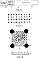
- information such as sound information can be recorded by printing in the form of an optically readable dot code on the recording/transmitting medium 4 such as a paper sheet.
- the dot code denoted by reference numeral 71 comprises a block group which includes blocks 72 including a predetermined number of dots and arranged in a two-dimensional matrix.
- Each block 72 which includes a predetermined number of dots is recognized to have a predetermined density in a broad view.
- FIG. 14 is an enlarged view of one of the blocks which constitute the dot code 71.
- the block 72 includes a data dot pattern section 73 which is obtained by modulating the data of the encoded sound file 141 such that pieces of the data are arranged in accordance with their bit values; and a block header section 74 indicative of information such as the address of the block 72 and disposed in a predetermined positional relationship with respect to the data dot pattern section 73.
- the block 72 further includes markers 75 situated at predetermined locations, for example, at its four corners, for recognizing the block 72; and a matching dot pattern 76 provided between adjacent ones of the markers 75 in a first direction.
- the block header section 74 is situated between adjacent ones of the markers 75 in a second direction.
- the dots provided in the block header section 74 and the matching dot pattern 76 have the same size as those (hereinafter referred to as "data dots") provided in the data dot pattern section 73.
- the data dots have a size of, for example, 40 - 80 ⁇ m.
- the markers 75 have a greater size than the data dots, and are recorded, on a recording medium, as circular dots having a diameter, for example, five times that of the data dots.
- the data of the encoded sound file 141 is modulated into a data dot pattern before being recorded.
- the modulation is performed to limit the number of data dots continuously arranged in order to discriminate the data dots from the markers 75. For example, when the diameter of the marker 75 is five time that of the data dot, the number of continuously arranged data dots must be limited to 4 or less.
- FIG. 14 shows a block 72 including (17 ⁇ 17) data dots
- the block 72 is not limited to this size, but may include (30 ⁇ 30) or (40 ⁇ 40) data dots. It should be noted that the lines which are arranged in the form of a grid are imaginary ones.
- the receiving apparatus 2 reproduces, using the data reproducing section 21, the encoded sound file data recorded on or in the recording/transmitting medium 4.
- a reproducing apparatus also described in detail in the publication EP 0,670,555 A1 can be sued as the data reproducing section 21.
- the data reproducing section 21 reproduces the encoded sound file data as described above, and also extracts a re-sampling frequency from the header section of the file. Then, it inputs the extracted re-sampling frequency f v to the compressed-sound-data decoding section 22 and the band adaptive type output data converting section 23, and also generates a cut-off frequency f w which is half the re-sampling frequency f v , thereby inputting it to the band adaptive type output data converting section 23. Further, the encoded sound data represented by the data reproducing section 21 is supplied to the compressed-sound-data decoding section 22.
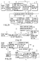
- the compressed-sound-data decoding section 22 comprises a process timing clock generating section 221, an analysis/synthesis encoded data decoding section (or a waveform encoded data decoding section) 222, and a sound frame buffer 223 as shown in FIG. 15.
- the re-sampling frequency f v extracted in the data reproducing section 21 is fed to the process timing clock generating section 221.
- the process timing clock generating section 221 divides the re-sampling frequency f v by the number of process unit samples to thereby determine the frequency of a clock signal indicative of a time point of processing in each encoding frame.
- the section 221 then creates a clock signal CLK of the determined frequency and feeds it to the analysis/synthesis encoded data decoding section 222.
- data d f reproduced by the data reproducing section 21 is once input to and stored in the sound frame buffer 223.
- the analysis/synthesis encoded data decoding section 222 responds to the clock signal CLK to thereby sequentially read data from the sound frame buffer 223 in units of one encoding frame, and then decode it, thereby outputting resultant data as decoded data d to the band adaptive type output data converting section 23 of the next stage.
- the structure of the above compressed-sound-data decoding section 22 is for performing real-time processing. Where re-sampled sound data is stored in, for example, a memory, read when necessary therefrom and subjected to analysis/synthesis encoding/decoding processing, no clock signal CLK is necessary since it is not always necessary to perform processing in units of one sound encoding frame and in a real-time manner.
- FIG. 16 shows the structure of the band adaptive type output data converting section 23.
- This section comprises an up-sampling converting section 231 and an adaptive digital low-pass filter 232.
- the re-sampling frequency f v and the cut-off frequency f w from the data reproducing section 21 are fed to the up-sampling converting section 231 and the adaptive digital low-pass filter 232, respectively.
- the up-sampling converting section 231 performs up-sampling of the decoded data d output from the compressed-sound-data decoding section 22, using a high frequency f u which is, for example, four times the re-sampling frequency f v .
- the up-sampling frequency f u is fed to the sound output processing section 24 of a post stage.
- the up-sampled data d u is subjected to the adaptive digital low-pass filter 232, where a frequency component higher than the cut-off frequency f w is cut off the data.
- the resultant data is fed to the sound output processing section 24.
- the sound output processing section 24 comprises an S/H & ADC 241, an LPF 242 and a pre-power-amplifier 243 as shown in FIG. 17.
- the up-sampling frequency f u from the up-sampling converting section 231 of the band adaptive type output data converting section 23 is input to the S/H & ADC 241, where data d o from the adaptive digital low-pass filter 232 of the band adaptive type output data converting section 23 is sampled and held using the up-sampling frequency f u , and subjected to D/A conversion.
- the signal which has been converted to an analog signal as a result of up-sampling by the up-sampling converting section 231, is then subjected to the LPF 242 where its high frequency component is cut.
- the LPF 242 employs the cut-off frequency f w , its cut-off characteristic may be gentle since pre-filtering is performed in the adaptive digital low-pass filter 232.
- the output of the LPF 242 is input as an analog sound signal to the pre-power-amplifier 243, amplified by it, then input to and output as an actual sound from the sound output device 5 such as a speaker.
- the frequency band setting section 121 sets the frequency band of a digital sound signal to be transmitted, and determines the cut-off frequency and re-sampling frequency of the digital sound signal on the basis of the set frequency band;
- the adaptive anti-aliasing filter 123 adaptively filters the to-be-transmitted digital sound signal on the basis of the cut-off frequency;
- the re-sampling converting section 124 re-samples the digital sound signal having passed through the filter 123, using the determined re-sampling frequency;
- the sound compression encoding section 13 subjects the re-sampled digital sound signal to compression encoding in units of a predetermined number of data samples, to thereby generate encoded data.
- the data recording section 14 records, as an encoded sound file 141 on the recording/transmitting medium 4, the encoded data 1413 and control data, such as the re-sampling frequency 1411, which relates to the cut-off frequency and/or re-sampling frequency determined by the frequency band setting section 121.
- the encoded sound file 141 is transmitted to the receiving apparatus 2 via the recording/transmitting medium 4.
- the data reproducing section 21 extracts the cut-off frequency and/or the re-sampling frequency determined by the frequency band setting section 121, using the re-sampling frequency 1411 contained in the encoded sound file 141 transmitted via the recording/transmitting medium 4; and the compressed-sound-data decoding section 22 performs decompression decoding corresponding to the compression encoding processing, using the extracted cut-off frequency and/or re-sampling frequency.
- a sound signal has its sound quality (sound band) adaptively limited by the adaptive anti-aliasing filter 123, and the resultant sound signal is sampled using a necessary sampling frequency, and encoded by the single sound compression encoding section 13, the amount of data can be controlled so as to realize sound quality sufficient to satisfy various purposes, which means that generation of an unnecessary amount of data can be avoided. Further, since the data amount can be controlled using a single compression encoding system, the transmitting apparatus can be made at low cost and simple in structure.
- the transmitting apparatus 1 transmits both the encoded data and control data relating to the cut-off frequency and/or the re-sampling frequency, while the receiving apparatus 2 extracts the control data to thereby reliably obtain the cut-off frequency/re-sampling frequency used to generate individual encoded data items. Accordingly, each encoded data item can be converted to a sound signal.
- an adaptive band is determined for each encoded sound data item, whereas in the second embodiment, it is determined for each input sound data item.
- M represents a positive integer such as 0, 1, ..., and indicates the total number of input sound samples.
- a single re-sampling frequency and cut-off frequency are determined from the entire input sound.
- the cut-off frequency When determining, using the ears of individuals, which band component is a major component, it is difficult to uniformly set the cut-off frequency at, for example, 6 kHz since such determination is based on their subjectivity and hence different determination results will be obtained between them.
- various sounds which each contain a major component of a certain band and minor components of other bands are filtered using different cut-off frequencies, and the resultant sounds are actually listened to and compared with each other, thereby causing, for example, a neural network to learn cut-off frequencies which can produce preferable sounds.
- a sound signal from the sound input device 3 is converted to digital data by the sound input processing section 11 as described above, and then input to the anti-aliasing filter 15.
- the anti-aliasing filter 15 has the same function as the adaptive anti-aliasing filter 123 of the first embodiment, the cut-off frequency f w of the filter 15 is set by the user via the record sound band setting section 17.
- a table sheet 8 which indicates the relationship between a to-be-recorded sound and the cut-off frequency f w and is used as an auxiliary member for permitting the user to select a desired cut-off frequency f w through the record sound band setting section 17.
- the table sheet 8 enables the user to easily know from the type of a to-be-recorded sound which cut-off frequency f w should be set. It is a matter of course that a table as described in the table sheet 8 may be set in the record sound band setting section 17 so that the user can select and set a sound type to thereby automatically set a cut-off frequency f w corresponding thereto.
- Sound data whose reflected noise is removed by the anti-aliasing filter 15 is input to the re-sampling converting section 16 which corresponds to the re-sampling converting section 124 of the first embodiment, where the data is re-sampled using the re-sampling frequency f v set by the record sound band setting section 17.
- the re-sampled sound data is input to the sound compression encoding section 13, where it is subjected to compression encoding in units of a predetermined number of data samples.
- the compression encoded data is input to the data recording section 14, where it is recorded as the encoded sound file 141 on the recording/transmitting medium 4.
- the encoded sound file 141 includes the re-sampling frequency 1411 as a header as in the first embodiment.
- the data reproducing section 21 reproduces the encoded sound file recorded on the recording/transmitting medium 4, and also extracts the re-sampling frequency from the header section.
- the extracted re-sampling frequency is input to the compressed-sound-data decoding section 22 and the band select type output data converting section 25, while the reproduced encoded sound data is input to the compressed-sound-data decoding section 22.
- the section 22 decodes the input encoded sound data and input the decoded sound data to the band select type output data converting section 25.
- the section 25 corresponds to the band adaptive type output data converting section 23 of the first embodiment, and is arranged to perform necessary up-sampling on the basis of the re-sampling frequency selected by the user and output from the data reproducing section 21, thereby inputting the resultant sound data to the sound output processing section 24.
- the section 24 performs D/A conversion, filtering, amplification, etc., and outputs a sound corresponding to the input sound data through the sound output device 5 such as a speaker, an earphone, a headphone, etc.
- a re-sampling frequency set in the reproduction sound band setting section 26 may be supplied to the compressed-sound-data decoding section 22 and the band select type output data converting section 25 as indicated by the broken lines in FIG. 19.
- the reproduction sound band setting section 26 includes, for example, a switch for permitting the user to optionally set one of a plurality of re-sampling frequencies f v as in the case of the record sound band setting section 17 of the transmitting apparatus 1, and also includes a display section for displaying the re-sampling frequency supplied from the data reproducing section 21.
- the re-sampling frequency is supplied to the compressed-sound-data decoding section 22 and the band select type output data converting section 25.
- FIG. 21 illustrates the structure of the fifth embodiment, in which elements similar to those of the first embodiment shown in FIG. 1 are denoted by corresponding reference numerals.
- the transmitting apparatus 1 comprises a sound input processing section 11' and a band adaptive type input data emphasizing/converting section 18, which are used instead of the sound input processing section 11 and the band adaptive type input data converting section 12, respectively.
- the band adaptive type output data converting section 23 is not employed, and the output of the compressed-sound-data decoding section 22 is directly supplied to the sound output processing section 24.
- the sound input processing section 11' is obtained by removing the sampling frequency converting section from the voice input processing section 11 shown in FIG. 2.
- the band adaptive type input data emphasizing/converting section 18 includes a major component band detecting section 181, an appropriate band determining/selecting section 182, a band emphasizing anti-aliasing filter 183, a buffer memory 184 and a re-sampling converting section 185. More specifically, digital sound data from the sound input processing section 11' is supplied to and stored in the buffer memory 184 corresponding to the buffer memory 122 of the first embodiment, and also supplied to the major component band detecting section 181 corresponding to the major component band detecting section 1211 of the first embodiment. The major component band detecting section 181 detects the major frequency band of the input digital sound data, and supplies the detection result to the appropriate band determining/selecting section 182.
- the section 182 has a structure obtained by removing the cut-off frequency and re-sampling frequency setting section 12126 from the appropriate band determining/selecting section 1212 shown in FIG. 7. Accordingly, in this embodiment, an appropriate band ID output from the maximum value detecting section 12125 is supplied as a major component band ID to the band emphasizing anti-aliasing filter 183.
- the band emphasizing anti-aliasing filter 183 has a setting condition table as shown in FIG. 24, and is arranged to refer to the setting table on the basis of the major component band ID output from the appropriate band determining/selecting section 182, thereby determining the cut-off frequency f w , the re-sampling frequency f v , and whether or not there is a band emphasizing filter, and supplying the re-sampling frequency f v to the re-sampling converting section 185, and also to the sound compression encoding section 13 and data recording section 14 which are located downstream of the band adaptive type input data emphasizing/converting section 18.
- the sound data obtained through the band emphasizing anti-aliasing filter 183 is input to a re-sampling converting section 185 corresponding to the re-sampling converting section 124 of the first embodiment, then again re-sampled using the re-sampling frequency f v , and supplied to the sound compression encoding section 13.
- the invention can provide cheap and easy-to-handle visual, aural information, in addition to conventional visual information such as images or characters.
Landscapes
- Engineering & Computer Science (AREA)
- Computer Networks & Wireless Communication (AREA)
- Signal Processing (AREA)
- Compression, Expansion, Code Conversion, And Decoders (AREA)
Applications Claiming Priority (2)
| Application Number | Priority Date | Filing Date | Title |
|---|---|---|---|
| JP1662798 | 1998-01-29 | ||
| JP10016627A JPH11215006A (ja) | 1998-01-29 | 1998-01-29 | ディジタル音声信号の送信装置及び受信装置 |
Publications (1)
| Publication Number | Publication Date |
|---|---|
| EP0933889A1 true EP0933889A1 (de) | 1999-08-04 |
Family
ID=11921606
Family Applications (1)
| Application Number | Title | Priority Date | Filing Date |
|---|---|---|---|
| EP99101205A Withdrawn EP0933889A1 (de) | 1998-01-29 | 1999-01-22 | Vorrichtung zum Senden und Vorrichtung zum Empfangen digitaler Tonsignale |
Country Status (2)
| Country | Link |
|---|---|
| EP (1) | EP0933889A1 (de) |
| JP (1) | JPH11215006A (de) |
Cited By (3)
| Publication number | Priority date | Publication date | Assignee | Title |
|---|---|---|---|---|
| US8214202B2 (en) | 2006-09-13 | 2012-07-03 | Telefonaktiebolaget L M Ericsson (Publ) | Methods and arrangements for a speech/audio sender and receiver |
| WO2014108677A1 (en) * | 2013-01-08 | 2014-07-17 | Meridian Audio Limited | Digital encapsulation of audio signals |
| WO2015189533A1 (en) * | 2014-06-10 | 2015-12-17 | Meridian Audio Limited | Digital encapsulation of audio signals |
Families Citing this family (3)
| Publication number | Priority date | Publication date | Assignee | Title |
|---|---|---|---|---|
| US6251077B1 (en) * | 1999-08-13 | 2001-06-26 | General Electric Company | Method and apparatus for dynamic noise reduction for doppler audio output |
| JP4538705B2 (ja) * | 2000-08-02 | 2010-09-08 | ソニー株式会社 | ディジタル信号処理方法、学習方法及びそれらの装置並びにプログラム格納媒体 |
| DE102008015702B4 (de) | 2008-01-31 | 2010-03-11 | Fraunhofer-Gesellschaft zur Förderung der angewandten Forschung e.V. | Vorrichtung und Verfahren zur Bandbreitenerweiterung eines Audiosignals |
Citations (5)
| Publication number | Priority date | Publication date | Assignee | Title |
|---|---|---|---|---|
| US4626827A (en) * | 1982-03-16 | 1986-12-02 | Victor Company Of Japan, Limited | Method and system for data compression by variable frequency sampling |
| EP0508581A2 (de) * | 1991-03-12 | 1992-10-14 | AT&T Corp. | Signalkompression unter Verwendung eines Empfindungsmodells |
| JPH05335968A (ja) * | 1992-05-29 | 1993-12-17 | Oki Electric Ind Co Ltd | 符号化装置及び復号化装置 |
| US5414796A (en) * | 1991-06-11 | 1995-05-09 | Qualcomm Incorporated | Variable rate vocoder |
| US5530750A (en) * | 1993-01-29 | 1996-06-25 | Sony Corporation | Apparatus, method, and system for compressing a digital input signal in more than one compression mode |
-
1998
- 1998-01-29 JP JP10016627A patent/JPH11215006A/ja not_active Withdrawn
-
1999
- 1999-01-22 EP EP99101205A patent/EP0933889A1/de not_active Withdrawn
Patent Citations (5)
| Publication number | Priority date | Publication date | Assignee | Title |
|---|---|---|---|---|
| US4626827A (en) * | 1982-03-16 | 1986-12-02 | Victor Company Of Japan, Limited | Method and system for data compression by variable frequency sampling |
| EP0508581A2 (de) * | 1991-03-12 | 1992-10-14 | AT&T Corp. | Signalkompression unter Verwendung eines Empfindungsmodells |
| US5414796A (en) * | 1991-06-11 | 1995-05-09 | Qualcomm Incorporated | Variable rate vocoder |
| JPH05335968A (ja) * | 1992-05-29 | 1993-12-17 | Oki Electric Ind Co Ltd | 符号化装置及び復号化装置 |
| US5530750A (en) * | 1993-01-29 | 1996-06-25 | Sony Corporation | Apparatus, method, and system for compressing a digital input signal in more than one compression mode |
Non-Patent Citations (1)
| Title |
|---|
| PATENT ABSTRACTS OF JAPAN vol. 018, no. 161 (E - 1526) 17 March 1994 (1994-03-17) * |
Cited By (10)
| Publication number | Priority date | Publication date | Assignee | Title |
|---|---|---|---|---|
| US8214202B2 (en) | 2006-09-13 | 2012-07-03 | Telefonaktiebolaget L M Ericsson (Publ) | Methods and arrangements for a speech/audio sender and receiver |
| WO2014108677A1 (en) * | 2013-01-08 | 2014-07-17 | Meridian Audio Limited | Digital encapsulation of audio signals |
| WO2015189533A1 (en) * | 2014-06-10 | 2015-12-17 | Meridian Audio Limited | Digital encapsulation of audio signals |
| KR20170023941A (ko) * | 2014-06-10 | 2017-03-06 | 레이네 에스.아.알.엘. | 오디오 신호의 디지털 캡슐화 |
| CN106575508A (zh) * | 2014-06-10 | 2017-04-19 | 瑞内特有限公司 | 音频信号的数字封装 |
| US10115410B2 (en) | 2014-06-10 | 2018-10-30 | Peter Graham Craven | Digital encapsulation of audio signals |
| US10867614B2 (en) | 2014-06-10 | 2020-12-15 | Mqa Limited | Digital encapsulation of audio signals |
| KR20210132222A (ko) * | 2014-06-10 | 2021-11-03 | 엠큐에이 리미티드 | 오디오 신호의 디지털 캡슐화 |
| KR20230028594A (ko) * | 2014-06-10 | 2023-02-28 | 엠큐에이 리미티드 | 오디오 신호의 디지털 캡슐화 |
| US12183356B2 (en) | 2014-06-10 | 2024-12-31 | Lenbrook Industries Limited | Digital encapsulation of audio signals |
Also Published As
| Publication number | Publication date |
|---|---|
| JPH11215006A (ja) | 1999-08-06 |
Similar Documents
| Publication | Publication Date | Title |
|---|---|---|
| US5136652A (en) | Amplitude enhanced sampled clipped speech encoder and decoder | |
| EP1986436A3 (de) | Vorrichtung für Audio- und/oder Videogenerierung und Verfahren zur Generierung von Audio- und/oder Videosignalen | |
| US20070052560A1 (en) | Bit-stream watermarking | |
| EP1298960A3 (de) | Digitales akustisches Wiedergabegerät, akustisches Gerät und akustisches Wiedergabesystem | |
| EP0933889A1 (de) | Vorrichtung zum Senden und Vorrichtung zum Empfangen digitaler Tonsignale | |
| US20030220801A1 (en) | Audio compression method and apparatus | |
| US7606711B2 (en) | Audio signal processing device, signal recovering device, audio signal processing method and signal recovering method | |
| JP3193437B2 (ja) | 伝送システム及び伝送システムに使用される受信機 | |
| EP2254123A3 (de) | Aufnahme- und Wiedergabegerät und -verfahren, Programmspeichermedium und Programm | |
| US20040064324A1 (en) | Bandwidth expansion using alias modulation | |
| CN1251467C (zh) | 具有特定的第一取样频率的数字信息信号的传输 | |
| EP1548713A3 (de) | Verfahren zur Wiedergabe von Daten zur Reduzierung der Beeinflussung der Neigung und Gerät zur Durchführung desselbigen | |
| JPH07183857A (ja) | 伝送システム | |
| US7248934B1 (en) | Method of transmitting a one-dimensional signal using a two-dimensional analog medium | |
| JPS60197059A (ja) | フアクシミリ装置 | |
| JP3875890B2 (ja) | 音声信号加工装置、音声信号加工方法及びプログラム | |
| JPS5921144A (ja) | 信号伝送方式およびその装置 | |
| WO1997040603A3 (de) | Verfahren und vorrichtung zum aufzeichnen/verarbeiten von authentischen tondaten | |
| JPH04249300A (ja) | 音声符復号化方法及びその装置 | |
| JP3130076B2 (ja) | 画像通信装置 | |
| JP2003216171A (ja) | 音声信号加工装置、信号復元装置、音声信号加工方法、信号復元方法及びプログラム | |
| KR0178713B1 (ko) | 오디오신호의 녹음.재생장치 | |
| JPH0723020A (ja) | 符号化制御方式 | |
| JPH1079166A (ja) | パルス符号変調されたディジタルオーディオ信号の記録及び再生のためのシステム | |
| JPH08167243A (ja) | デジタルオーディオシステムおよび再生装置並びに記録装置およびデジタルコピー方法 |
Legal Events
| Date | Code | Title | Description |
|---|---|---|---|
| PUAI | Public reference made under article 153(3) epc to a published international application that has entered the european phase |
Free format text: ORIGINAL CODE: 0009012 |
|
| AK | Designated contracting states |
Kind code of ref document: A1 Designated state(s): AT BE CH CY DE DK ES FI FR GB GR IE IT LI LU MC NL PT SE |
|
| AX | Request for extension of the european patent |
Free format text: AL;LT;LV;MK;RO;SI |
|
| 17P | Request for examination filed |
Effective date: 19990825 |
|
| AKX | Designation fees paid |
Free format text: AT BE CH CY DE DK ES FI FR GB GR IE IT LI LU MC NL PT SE |
|
| STAA | Information on the status of an ep patent application or granted ep patent |
Free format text: STATUS: THE APPLICATION HAS BEEN WITHDRAWN |
|
| 18W | Application withdrawn |
Withdrawal date: 20011108 |