EP0934897A1 - Verfahren zur überprüfung von textilspulen und vorrichtung für seine durchführung - Google Patents
Verfahren zur überprüfung von textilspulen und vorrichtung für seine durchführung Download PDFInfo
- Publication number
- EP0934897A1 EP0934897A1 EP97908297A EP97908297A EP0934897A1 EP 0934897 A1 EP0934897 A1 EP 0934897A1 EP 97908297 A EP97908297 A EP 97908297A EP 97908297 A EP97908297 A EP 97908297A EP 0934897 A1 EP0934897 A1 EP 0934897A1
- Authority
- EP
- European Patent Office
- Prior art keywords
- bobbin
- image
- images
- sensors
- end faces
- Prior art date
- Legal status (The legal status is an assumption and is not a legal conclusion. Google has not performed a legal analysis and makes no representation as to the accuracy of the status listed.)
- Granted
Links
- 238000000034 method Methods 0.000 title claims abstract description 20
- 238000009987 spinning Methods 0.000 title claims description 6
- 230000007547 defect Effects 0.000 claims abstract description 38
- 238000012545 processing Methods 0.000 claims abstract description 8
- 239000000463 material Substances 0.000 claims abstract description 6
- 238000004590 computer program Methods 0.000 claims abstract description 3
- 238000007689 inspection Methods 0.000 claims abstract description 3
- 238000001514 detection method Methods 0.000 claims description 9
- 230000003287 optical effect Effects 0.000 claims description 8
- 239000011159 matrix material Substances 0.000 claims description 7
- 238000004804 winding Methods 0.000 claims description 7
- 239000003086 colorant Substances 0.000 claims description 2
- 238000011161 development Methods 0.000 claims description 2
- 238000012216 screening Methods 0.000 claims description 2
- 238000006073 displacement reaction Methods 0.000 claims 1
- 238000010586 diagram Methods 0.000 description 2
- 230000000694 effects Effects 0.000 description 2
- 238000006748 scratching Methods 0.000 description 2
- 230000002393 scratching effect Effects 0.000 description 2
- 238000001914 filtration Methods 0.000 description 1
- 230000015654 memory Effects 0.000 description 1
- 238000012546 transfer Methods 0.000 description 1
Images



Classifications
-
- G—PHYSICS
- G01—MEASURING; TESTING
- G01N—INVESTIGATING OR ANALYSING MATERIALS BY DETERMINING THEIR CHEMICAL OR PHYSICAL PROPERTIES
- G01N21/00—Investigating or analysing materials by the use of optical means, i.e. using sub-millimetre waves, infrared, visible or ultraviolet light
- G01N21/84—Systems specially adapted for particular applications
- G01N21/88—Investigating the presence of flaws or contamination
- G01N21/89—Investigating the presence of flaws or contamination in moving material, e.g. running paper or textiles
- G01N21/8914—Investigating the presence of flaws or contamination in moving material, e.g. running paper or textiles characterised by the material examined
- G01N21/8915—Investigating the presence of flaws or contamination in moving material, e.g. running paper or textiles characterised by the material examined non-woven textile material
-
- B—PERFORMING OPERATIONS; TRANSPORTING
- B65—CONVEYING; PACKING; STORING; HANDLING THIN OR FILAMENTARY MATERIAL
- B65H—HANDLING THIN OR FILAMENTARY MATERIAL, e.g. SHEETS, WEBS, CABLES
- B65H63/00—Warning or safety devices, e.g. automatic fault detectors, stop-motions ; Quality control of the package
- B65H63/006—Warning or safety devices, e.g. automatic fault detectors, stop-motions ; Quality control of the package quality control of the package
-
- G—PHYSICS
- G01—MEASURING; TESTING
- G01N—INVESTIGATING OR ANALYSING MATERIALS BY DETERMINING THEIR CHEMICAL OR PHYSICAL PROPERTIES
- G01N21/00—Investigating or analysing materials by the use of optical means, i.e. using sub-millimetre waves, infrared, visible or ultraviolet light
- G01N21/84—Systems specially adapted for particular applications
- G01N21/88—Investigating the presence of flaws or contamination
- G01N21/95—Investigating the presence of flaws or contamination characterised by the material or shape of the object to be examined
- G01N21/952—Inspecting the exterior surface of cylindrical bodies or wires
-
- B—PERFORMING OPERATIONS; TRANSPORTING
- B65—CONVEYING; PACKING; STORING; HANDLING THIN OR FILAMENTARY MATERIAL
- B65H—HANDLING THIN OR FILAMENTARY MATERIAL, e.g. SHEETS, WEBS, CABLES
- B65H2701/00—Handled material; Storage means
- B65H2701/30—Handled filamentary material
- B65H2701/31—Textiles threads or artificial strands of filaments
Definitions
- This invention relates to a method for inspecting spinning bobbins and system for implementing such method.
- the method and system according to the invention are applied to scanning yarn bobbins after their winding process on a core which gives rise to one or more stations embedded in a conveyor line for said recently formed bobbins carriage towards a point of use or storage.
- the method and system proposed are adapted for processing bobbins having different sizes, colours and material, comprising a step for acquiring (capturing and lighting) images on the bobbin surface, a second step of processing said images through digitizing and an end process by means of an analysis computer program applied to withdraw and assess the defects.
- the system according to the invention allows to detect a great number of defects which can appear on the spinning bobbins and namely, broken filaments, loops, webbing, scratching or defibered parts and blows, stains on the bobbin end faces and on its sides, scratching, blows and unevenness, deformations, cavings and bobbin density, tube colour and yarn butt end as well as circles or stains on the bobbin end faces.
- the system is based on a generally sequential and matched action of a plurality of image acquiring sensors, several of which are moveable in order to be able to locate them at predetermined points before starting each cycle of image capture of a related detection or scanning step, generally specific for each of the defects and in which a whole bobbin area is scanned, sector by sector, and the images acquired are also processed one by one or integrated with other images corresponding to a scanning step.
- a lighting has been provided specially adapted to each case whose arrangement, matched with a suitable optics, provides a sufficient field depth effect in order that the defects present in the sector are perfectly focused in resulting image.
- Japanese patent application 62-62938 and U.S. Pat No. 5,138,151 disclose methods for detecting based on sensors for acquiring image by line by line reading, provided to give rise to a station embedded in a line to transfer bobbins toward a storage or service area.
- Japanese patent application 134105 and U.S Patent No. 5,359,408 disclose devices for inspecting spinning bobbins comprising a matrix type camera image acquisition means, the later of these backgrounds disclosing arrangements applied for detecting different defects with the use of several types of lighting sources such as ultraviolet rays, fluorescent or other.
- this invention proposes and which namely provides with an effect of field depth such it allows to accurately focus the defects at each scanned sector which significantly facilitates their identification.
- the method according to the invention is based on several bobbin scanning steps, shooting at each step a plurality of images from different areas of a bobbin to be inspected, in general sequentially and at each step under particular lighting conditions and with a definite position of several specific, i.e. distinct image acquisition sensors provided to facilitate for each of said lighting conditions and definite positions of said specific sensors an identification-withdrawal of some special defects to be detected, moving accordingly either said bobbin or said image acquisition sensors or both to scan, sector by sector, a whole surface of interest.
- each of the focused images associated to a particular defect or group of defects is likewise processed in a single way or integrated with other images corresponding to a scanning step obtained through the same image acquisition sensor, by an assessing program, depending on an specific defect to determine and regardless of the size, colour or material of said bobbin
- inspecting bobbin end faces is achieved by image acquisition by means of at least three different arrangements of the image acquisition sensors and lighting sources to be used, two of the sensors on the sides and a third one located above the bobbin end faces, with the peculiarity that the side sensors are moveable, moving in parallel to the bobbin shaft to cover end faces defects and on its side wall by automatically governed driving means operation.
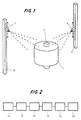
- the system comprises one or several working stations which include a plurality of image acquisition sensors such as a matrix camera, with at least one image sensor above each end face, with its optical axis approximately parallel to the bobbin shaft, but moved sideways with respect thereof and other image sensors installed associated to columns parallel to the bobbin winding shaft with their optical axis oriented perpendicular to said bobbin and moveable along said columns in order to be positioned level or slightly above each of the end faces or covering the bobbin side area.
- image acquisition sensors such as a matrix camera
- this system includes means to rotate the bobbin at constant speed in order to make workable a sequential shot of a plurality of images thereof and comprising in addition a plurality of lighting sources associated one by one to related image sensors and if fit moveable with same, or fixed, operating individually jointly with one determined of the image sensors and with specific spatial orientations.
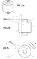
- Figure 3a shows a bobbin, and it is indicated that on its top face there exists webbing and Fig. 3b and 3c show a side elevation and plan view, respectively of the image acquisition sensor and lighting source arrangements used in this case according to the system proposed. In the event of Fig. 3c an alternative arrangement of the lighting source has been also shown.
- Figure 4a is a perspective view of a bobbin in which, on the top portion of the winding core protruding from the bobbin a yarn butt end is emphasized and Fig. 4b and 4c show in a side elevation and plan view the image acquisition sensor and lighting source arrangement used to detect this defect according to the system proposed.
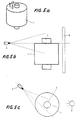
- Figure 5a shows in perspective a bobbin which at its top face shows loops and broken filaments and Fig. 5b and 5c show in side elevation and plan view the image acquisition sensor and lighting source arrangement used according to the system proposed. It must be emphasized in addition that inspecting tasks detailed in Fig. 3a to 5c can be carried out by a same sensor or matrix camera as those shown in Fig. 1, conveniently moving the camera involved along the supporting column with suitable driving means, automatically controlled.
- bobbins are drawn in perspective which in their top face show circles or stains, respectively, the image acquisition sensor and lighting sources related arrangements for inspecting according to the invention being illustrated in elevation and plan view in Fig. 6c and 6d.
- Fig. 7a shows a drawing in perspective of a bobbin with some stains on its side surface
- Fig. 7b and 7c showing the image acquisition sensor and lighting source arrangements used for inspecting this particular defect.
- the camera used can be same as the one used for inspecting defects of Fig. 3a to 5c, with a convenient moving and use of specific lighting means.
- FIG. 8a shows in perspective a bobbin with deformations of its body and Fig. 8b and 8c show the image acquisition sensor and lighting source arrangement used to assess this defect.
- the system comprises two side columns 20, 21 in which two image sensors 3, 4 such as a matrix camera are located, designed to cover the bobbin top and lower end faces, which sensors can be moved by suitable electromechanical means along said columns 20, 21 in order to also focus a bobbin side strip 1, 1a.
- Fig. 2 schematically shows an operation diagram of the means for processing each of the images comprising an image acquisition block 30, a block for improving said image 31, a filtering step 32, a binarization step 33 of the image, a block for extracting characteristics 34 and a final classification step 35.
- Each of the images acquired are converted into two-colour digital images and from said two-colour image elements those geometrical characteristics particular for each defect are withdrawn, which compared against preestablished determined values stored in memories allow to assess whether a defect is existing or not.
- the system comprises, for detecting broken filaments, loops or other protrusions or bulging from the surface of one of the bobbin ends or scratches, i.e. defibered parts as shows Fig. 5a, an image sensor 3 whose optical axis is approximately parallel to the plane defined by the bobbin end face 1 and is arranged approximately level with said face and an elongated lighting source 9 for adapting bobbin different lengths located in a sector comprised between 135 and 180 degrees, clockwise far away with respect to said image sensor 3 so that reflection is helped and said image sensor blinding is prevented said lighting cooperating in a suitable focus for detecting defects in the sector.
- the same image sensor 3 applied to detect broken filaments and loops can be operated in order to detect webbing, scratches and blows, on bobbin end faces 1, whose detecting step is shown in Fig. 3a to 3c for which said sensor 3 optical axis is displaced in elevation with respect to the plane defined by the bobbin end face 1 so that all said end face remains always visible in the field of view and in that an elongated lighting source 7 is used, having a development parallel to the bobbin shaft 2, for adapting it to several lengths, located in a sector between 270 to 350 degrees far away, clockwise, with respect to said image sensor 3, 4 preventing blinding it and helping the light reflection from the defect to be detected.
- Fig. 3c shows an alternative lighting source 10 also suitable for detecting webbing, located within a sector about 45 to 90 degrees far away, clockwise, elongated but parallel to one of the bobbin end faces 1, 1a with a screening such to allow a beam of light projection following a plane with an about 30 degrees slope above the one corresponding to the bobbin end face 1, 1a.
- Fig. 4a to 4c shows the butt end yarn and winding core colour protruding from the bobbin by its ends detection step for which same image sensor is used as for detecting the webbing 3 which has incorporated in this case a lighting source 8, 8a arranged behind the lens of said image acquisition sensor in order it produces an image by reflected light.
- the bobbin side stains and unevenness or bulging are detected by means of at least one of the image acquisition sensors 3, 4 applied to cover the bobbin two end faces 1 conveniently displaced along the columns 20, 21 to focus the area of interest whose location has been illustrated in Fig. 7a to 7c.
- each of the image acquisition sensors 5, 5a located above the bobbin end faces 1, 1a has available a lighting source 11a, 11b located behind the sensor lens and which allows to detect circles and stains in said two faces as well as to detect webbing which cannot be detected with specific means applied to their detection.
- Fig. 8a to 8c an additional image detection sensor 6 has been shown which allows to capture the complete bobbin image 1, 1a with a suitable resolution, providing a focusing and field depth such that the bobbin outline is detected by contrast of it with respect to a lighting source 12, opposed located behind said bobbin, allowing to calculate bobbin sizes and density, as well as determining the bobbin cavings and deformations.
Landscapes
- Engineering & Computer Science (AREA)
- Quality & Reliability (AREA)
- Textile Engineering (AREA)
- Physics & Mathematics (AREA)
- Health & Medical Sciences (AREA)
- Life Sciences & Earth Sciences (AREA)
- Chemical & Material Sciences (AREA)
- Analytical Chemistry (AREA)
- Biochemistry (AREA)
- General Health & Medical Sciences (AREA)
- General Physics & Mathematics (AREA)
- Immunology (AREA)
- Pathology (AREA)
- Investigating Materials By The Use Of Optical Means Adapted For Particular Applications (AREA)
- Treatment Of Fiber Materials (AREA)
- Investigating Or Analyzing Materials By The Use Of Magnetic Means (AREA)
Applications Claiming Priority (1)
| Application Number | Priority Date | Filing Date | Title |
|---|---|---|---|
| PCT/ES1997/000070 WO1998041466A1 (es) | 1997-03-19 | 1997-03-19 | Metodo de inspeccion de bobinas de hilatura y sistema para su puesta en practica |
Publications (2)
| Publication Number | Publication Date |
|---|---|
| EP0934897A1 true EP0934897A1 (de) | 1999-08-11 |
| EP0934897B1 EP0934897B1 (de) | 2001-07-04 |
Family
ID=8297879
Family Applications (1)
| Application Number | Title | Priority Date | Filing Date |
|---|---|---|---|
| EP97908297A Expired - Lifetime EP0934897B1 (de) | 1997-03-19 | 1997-03-19 | Verfahren zur überprüfung von textilspulen und vorrichtung für seine durchführung |
Country Status (6)
| Country | Link |
|---|---|
| US (1) | US6216432B1 (de) |
| EP (1) | EP0934897B1 (de) |
| DE (1) | DE69705532T2 (de) |
| ES (1) | ES2160929T3 (de) |
| GR (1) | GR3036800T3 (de) |
| WO (1) | WO1998041466A1 (de) |
Cited By (3)
| Publication number | Priority date | Publication date | Assignee | Title |
|---|---|---|---|---|
| EP3718939A1 (de) | 2019-04-03 | 2020-10-07 | Fitesa S.A. | Vorrichtung und verfahren zur erkennung des vorhandenseins von abnormalitäten in einer rolle |
| WO2021229344A1 (en) * | 2020-05-12 | 2021-11-18 | Thema 2 S.R.L. | Device and method for automatically checking the quality of a spool of thread for fabrics |
| US12586174B2 (en) | 2024-02-04 | 2026-03-24 | Zhejiang Hengyi Petrochemical Co., Ltd. | Method for processing yarn spindle data, electronic device and storage medium |
Families Citing this family (14)
| Publication number | Priority date | Publication date | Assignee | Title |
|---|---|---|---|---|
| WO2000020318A1 (es) * | 1998-10-01 | 2000-04-13 | Cognivision Research, Sl | Instalacion para inspeccion optica de bobinas |
| DE20218115U1 (de) * | 2002-11-22 | 2004-04-01 | Autefa Automation Gmbh | Vermessungseinrichtung für Filamentspulen |
| RU2275320C2 (ru) * | 2004-07-19 | 2006-04-27 | Костромской государственный технологический университет | Способ контроля формы паковки и устройство для его осуществления |
| ES2277710B1 (es) * | 2004-10-06 | 2008-05-16 | Asociacion De Investigacion De La Industria Textil | Sistema para la deteccion de mezclas en conos de hilo en crudo, en linea de produccion, transporte y/o almacenamiento. |
| CN101223554A (zh) * | 2005-05-14 | 2008-07-16 | 欧瑞康纺织有限及两合公司 | 用于模拟纤维制品可视平面图案的方法和设备以及用于制造bcf丝的方法和设备 |
| FR2887237B1 (fr) * | 2005-06-21 | 2007-09-21 | Rieter Textile Machinery Fr | Methode de pilotage d'un procede de transformation de fils |
| DE102009058720A1 (de) * | 2009-12-17 | 2011-06-22 | Oerlikon Textile GmbH & Co. KG, 42897 | Verfahren und Vorrichtung zur Ermittlung der Orientierung einer Kreuzspulenhülse |
| KR101537552B1 (ko) * | 2015-05-28 | 2015-07-17 | 금오공과대학교 산학협력단 | 4분원 이미지 처리기법을 이용한 Type-I 원사 패키지 권취불량의 자동검출 장치 및 방법 |
| CN109187370B (zh) * | 2018-08-10 | 2021-04-02 | 江苏恒神股份有限公司 | 一种碳纤维颜色差异检测方法 |
| IT201900009636A1 (it) * | 2019-06-20 | 2020-12-20 | Thema 2 S R L | Dispositivo e relativo metodo per il controllo automatico della tonalità di colore di una bobina di filo |
| EP3848311A1 (de) * | 2020-01-07 | 2021-07-14 | Lenzing Aktiengesellschaft | Automatische qualitätskontrolle von spulen |
| US11981065B1 (en) * | 2020-07-06 | 2024-05-14 | Columbia Insurance Company | Systems and methods for manufacturing colored product |
| CN116046784A (zh) * | 2022-12-08 | 2023-05-02 | 杭州电子科技大学 | 一种丝饼外观检测设备及其控制方法 |
| CN116256371A (zh) * | 2023-02-28 | 2023-06-13 | 广州赛奥碳纤维技术股份有限公司 | 一种碳纤维卷线质量实时检测方法、装置及存储介质 |
Family Cites Families (10)
| Publication number | Priority date | Publication date | Assignee | Title |
|---|---|---|---|---|
| JPS6186370A (ja) * | 1984-10-01 | 1986-05-01 | Toray Ind Inc | パツケ−ジ自動検査装置 |
| JPS6262937A (ja) * | 1985-09-10 | 1987-03-19 | Murata Mach Ltd | 巻糸パツケ−ジの巻形検査装置 |
| JPS6413376A (en) * | 1987-07-06 | 1989-01-18 | Teijin Ltd | Yarn package appearance checker |
| JPH02265867A (ja) * | 1989-04-04 | 1990-10-30 | Murata Mach Ltd | パッケージの異常部検出方法 |
| US5315366A (en) * | 1991-04-09 | 1994-05-24 | Murata Kikai Kabushiki Kaisha | Yarn package inspecting apparatus |
| DE4216729A1 (de) * | 1991-05-23 | 1992-11-26 | Murata Machinery Ltd | Vorrichtung zum kontrollieren von fadenspulen |
| CH686779A5 (de) * | 1993-10-29 | 1996-06-28 | Luwa Ag Zellweger | Vorrichtung zur Ueberpruefung der Wickelqualitaet von Garnspulen und Verwendung der Vorrichtung an einer Spul- oder Spinnmaschine. |
| JPH07125925A (ja) * | 1993-11-04 | 1995-05-16 | Murata Mach Ltd | パッケージ検査装置 |
| TW299035U (en) * | 1994-07-11 | 1997-02-21 | Barmag Barmer Maschf Co Ltd | Method of optically measuring the surface of yarn packages |
| US5815198A (en) * | 1996-05-31 | 1998-09-29 | Vachtsevanos; George J. | Method and apparatus for analyzing an image to detect and identify defects |
-
1997
- 1997-03-19 ES ES97908297T patent/ES2160929T3/es not_active Expired - Lifetime
- 1997-03-19 EP EP97908297A patent/EP0934897B1/de not_active Expired - Lifetime
- 1997-03-19 DE DE69705532T patent/DE69705532T2/de not_active Expired - Lifetime
- 1997-03-19 WO PCT/ES1997/000070 patent/WO1998041466A1/es not_active Ceased
-
1998
- 1998-11-19 US US09/197,089 patent/US6216432B1/en not_active Expired - Fee Related
-
2001
- 2001-10-04 GR GR20010401662T patent/GR3036800T3/el not_active IP Right Cessation
Non-Patent Citations (1)
| Title |
|---|
| See references of WO9841466A1 * |
Cited By (4)
| Publication number | Priority date | Publication date | Assignee | Title |
|---|---|---|---|---|
| EP3718939A1 (de) | 2019-04-03 | 2020-10-07 | Fitesa S.A. | Vorrichtung und verfahren zur erkennung des vorhandenseins von abnormalitäten in einer rolle |
| WO2020202050A1 (en) | 2019-04-03 | 2020-10-08 | Fitesa S.A. | Device and method for detecting the presence of abnormalities in a reel |
| WO2021229344A1 (en) * | 2020-05-12 | 2021-11-18 | Thema 2 S.R.L. | Device and method for automatically checking the quality of a spool of thread for fabrics |
| US12586174B2 (en) | 2024-02-04 | 2026-03-24 | Zhejiang Hengyi Petrochemical Co., Ltd. | Method for processing yarn spindle data, electronic device and storage medium |
Also Published As
| Publication number | Publication date |
|---|---|
| ES2160929T3 (es) | 2001-11-16 |
| DE69705532T2 (de) | 2002-05-16 |
| DE69705532D1 (de) | 2001-08-09 |
| WO1998041466A1 (es) | 1998-09-24 |
| GR3036800T3 (en) | 2002-01-31 |
| US6216432B1 (en) | 2001-04-17 |
| EP0934897B1 (de) | 2001-07-04 |
Similar Documents
| Publication | Publication Date | Title |
|---|---|---|
| EP0934897B1 (de) | Verfahren zur überprüfung von textilspulen und vorrichtung für seine durchführung | |
| US6580813B1 (en) | Method and apparatus for detecting residual yarn on spinning cop tubes | |
| US4410278A (en) | Method and apparatus for appearance inspection | |
| CN110596134B (zh) | 一种基于图像采集的片状玻璃边缘瑕疵检测方法 | |
| US4223346A (en) | Automatic defect detecting inspection apparatus | |
| US5528359A (en) | Image scanning apparatus and method | |
| JP4351522B2 (ja) | パターン欠陥検査装置およびパターン欠陥検査方法 | |
| RU2735806C1 (ru) | Способ проверки печатного цилиндра и соответствующая установка | |
| EP0421606B1 (de) | Kugeldruckhärtetester | |
| US6633383B1 (en) | Method and apparatus for the automated inspection of yarn packages | |
| EP0179309A2 (de) | Automatische Fehlernachweisvorrichtung | |
| JPH07318498A (ja) | 非接触表面傷検出方法および非接触表面傷検出装置 | |
| CA2057670A1 (en) | Method of and apparatus for inspecting transparent object for defect | |
| EP0816833A2 (de) | Beleuchtungseinheit und -verfahren | |
| EP1943502B1 (de) | Vorrichtungen und verfahren zur überprüfung einer verbundstruktur auf defekte | |
| US7106432B1 (en) | Surface inspection system and method for using photo detector array to detect defects in inspection surface | |
| JPH06294749A (ja) | 板ガラスの欠点検査方法 | |
| EP0838026B1 (de) | Prüfen der oberfläche eines objekts | |
| US6970238B2 (en) | System for inspecting the surfaces of objects | |
| JP4739044B2 (ja) | 外観検査装置 | |
| TW432440B (en) | Method and device for inspecting fluorescent screen of cathode ray tube | |
| JP2846052B2 (ja) | 円筒体の検査装置 | |
| JPH09304294A (ja) | 被検査物の表面検査方法及びその装置 | |
| JP2869338B2 (ja) | 巻糸ボビンの汚れ検出装置 | |
| JPH10176994A (ja) | 円筒体の内面検査装置 |
Legal Events
| Date | Code | Title | Description |
|---|---|---|---|
| PUAI | Public reference made under article 153(3) epc to a published international application that has entered the european phase |
Free format text: ORIGINAL CODE: 0009012 |
|
| 17P | Request for examination filed |
Effective date: 19990319 |
|
| AK | Designated contracting states |
Kind code of ref document: A1 Designated state(s): BE DE ES FR GB GR IT |
|
| 17Q | First examination report despatched |
Effective date: 19991104 |
|
| GRAG | Despatch of communication of intention to grant |
Free format text: ORIGINAL CODE: EPIDOS AGRA |
|
| GRAG | Despatch of communication of intention to grant |
Free format text: ORIGINAL CODE: EPIDOS AGRA |
|
| GRAH | Despatch of communication of intention to grant a patent |
Free format text: ORIGINAL CODE: EPIDOS IGRA |
|
| GRAG | Despatch of communication of intention to grant |
Free format text: ORIGINAL CODE: EPIDOS AGRA |
|
| GRAH | Despatch of communication of intention to grant a patent |
Free format text: ORIGINAL CODE: EPIDOS IGRA |
|
| GRAH | Despatch of communication of intention to grant a patent |
Free format text: ORIGINAL CODE: EPIDOS IGRA |
|
| GRAA | (expected) grant |
Free format text: ORIGINAL CODE: 0009210 |
|
| AK | Designated contracting states |
Kind code of ref document: B1 Designated state(s): BE DE ES FR GB GR IT |
|
| REF | Corresponds to: |
Ref document number: 69705532 Country of ref document: DE Date of ref document: 20010809 |
|
| ITF | It: translation for a ep patent filed | ||
| REG | Reference to a national code |
Ref country code: ES Ref legal event code: FG2A Ref document number: 2160929 Country of ref document: ES Kind code of ref document: T3 |
|
| ET | Fr: translation filed | ||
| REG | Reference to a national code |
Ref country code: GB Ref legal event code: IF02 |
|
| REG | Reference to a national code |
Ref country code: GR Ref legal event code: EP Ref document number: 20010401662 Country of ref document: GR |
|
| PLBE | No opposition filed within time limit |
Free format text: ORIGINAL CODE: 0009261 |
|
| STAA | Information on the status of an ep patent application or granted ep patent |
Free format text: STATUS: NO OPPOSITION FILED WITHIN TIME LIMIT |
|
| 26N | No opposition filed | ||
| PGFP | Annual fee paid to national office [announced via postgrant information from national office to epo] |
Ref country code: BE Payment date: 20040315 Year of fee payment: 8 |
|
| PGFP | Annual fee paid to national office [announced via postgrant information from national office to epo] |
Ref country code: GR Payment date: 20040330 Year of fee payment: 8 |
|
| PG25 | Lapsed in a contracting state [announced via postgrant information from national office to epo] |
Ref country code: BE Free format text: LAPSE BECAUSE OF NON-PAYMENT OF DUE FEES Effective date: 20050331 |
|
| BERE | Be: lapsed |
Owner name: *COGNIVISION RESEARCH SL Effective date: 20050331 |
|
| PG25 | Lapsed in a contracting state [announced via postgrant information from national office to epo] |
Ref country code: GR Free format text: LAPSE BECAUSE OF NON-PAYMENT OF DUE FEES Effective date: 20051004 |
|
| BERE | Be: lapsed |
Owner name: *COGNIVISION RESEARCH SL Effective date: 20050331 |
|
| PGFP | Annual fee paid to national office [announced via postgrant information from national office to epo] |
Ref country code: GB Payment date: 20100327 Year of fee payment: 14 |
|
| PGFP | Annual fee paid to national office [announced via postgrant information from national office to epo] |
Ref country code: IT Payment date: 20100331 Year of fee payment: 14 Ref country code: DE Payment date: 20100528 Year of fee payment: 14 |
|
| PGFP | Annual fee paid to national office [announced via postgrant information from national office to epo] |
Ref country code: FR Payment date: 20100809 Year of fee payment: 14 |
|
| GBPC | Gb: european patent ceased through non-payment of renewal fee |
Effective date: 20110319 |
|
| REG | Reference to a national code |
Ref country code: FR Ref legal event code: ST Effective date: 20111130 |
|
| PG25 | Lapsed in a contracting state [announced via postgrant information from national office to epo] |
Ref country code: DE Free format text: LAPSE BECAUSE OF NON-PAYMENT OF DUE FEES Effective date: 20111001 Ref country code: FR Free format text: LAPSE BECAUSE OF NON-PAYMENT OF DUE FEES Effective date: 20110331 |
|
| PG25 | Lapsed in a contracting state [announced via postgrant information from national office to epo] |
Ref country code: IT Free format text: LAPSE BECAUSE OF NON-PAYMENT OF DUE FEES Effective date: 20110319 Ref country code: GB Free format text: LAPSE BECAUSE OF NON-PAYMENT OF DUE FEES Effective date: 20110319 |
|
| REG | Reference to a national code |
Ref country code: DE Ref legal event code: R119 Ref document number: 69705532 Country of ref document: DE Effective date: 20111001 |
|
| PGFP | Annual fee paid to national office [announced via postgrant information from national office to epo] |
Ref country code: ES Payment date: 20120424 Year of fee payment: 16 |
|
| REG | Reference to a national code |
Ref country code: ES Ref legal event code: FD2A Effective date: 20140609 |
|
| PG25 | Lapsed in a contracting state [announced via postgrant information from national office to epo] |
Ref country code: ES Free format text: LAPSE BECAUSE OF NON-PAYMENT OF DUE FEES Effective date: 20130320 |