EP0935126A2 - Flüssigkeitsspiegelanzeiger zum Gebrauch in einem Fahrzeug - Google Patents
Flüssigkeitsspiegelanzeiger zum Gebrauch in einem Fahrzeug Download PDFInfo
- Publication number
- EP0935126A2 EP0935126A2 EP98123924A EP98123924A EP0935126A2 EP 0935126 A2 EP0935126 A2 EP 0935126A2 EP 98123924 A EP98123924 A EP 98123924A EP 98123924 A EP98123924 A EP 98123924A EP 0935126 A2 EP0935126 A2 EP 0935126A2
- Authority
- EP
- European Patent Office
- Prior art keywords
- vehicle
- liquid level
- indicated
- fuel
- speed
- Prior art date
- Legal status (The legal status is an assumption and is not a legal conclusion. Google has not performed a legal analysis and makes no representation as to the accuracy of the status listed.)
- Granted
Links
Images

Classifications
-
- G—PHYSICS
- G01—MEASURING; TESTING
- G01F—MEASURING VOLUME, VOLUME FLOW, MASS FLOW OR LIQUID LEVEL; METERING BY VOLUME
- G01F23/00—Indicating or measuring liquid level or level of fluent solid material, e.g. indicating in terms of volume or indicating by means of an alarm
- G01F23/80—Arrangements for signal processing
- G01F23/802—Particular electronic circuits for digital processing equipment
- G01F23/804—Particular electronic circuits for digital processing equipment containing circuits handling parameters other than liquid level
Definitions
- the present invention relates generally to a liquid level gauge for use on a vehicle and, more particularly, to a liquid level gauge for indicating a liquid level in a tank on board a vehicle at response rates corresponding to the current speed of the vehicle on a real time basis.
- Japanese Published Examined Patent Application No. Sho 60-1567 discloses the following proposals: detect a remaining fuel quantity in a fuel tank of a vehicle in terms of interelectrode capacitance, convert the detected value of interelectrode capacitance into an oscillation frequency of an RC oscillator, change time intervals at which to measure a pulse count of the oscillation frequency between a stopped and a running state of the vehicle, and have the remaining fuel quantity indicated on an indicator on the basis of an average of the measured pulse counts.
- the cited patent also includes the following proposals: use a float-equipped potentiometer type or a wire wound resistor type level gauge to detect the remaining fuel quantity in the fuel tank, cause remaining quantity detection signals in analog form from the level gauge to be input to an integrator for integration using different time constants between the stopped and the running state of the vehicle, and have the remaining fuel quantity indicated on the indicator on the basis of the integrated value.
- the intervals at which to measure the pulse count are shortened and a shorter time constant is used on the integrator.
- the measuring intervals are prolonged and a longer time interval is used on the integrator.
- Two-wheel vehicles when parked, generally have their side stand extended for support. When started to go on the road, the vehicle has its side stand folded off the ground to run in upright posture. Between the parked state (side stand extended) and the running state (side stand folded), the level in the fuel tank of the vehicle fluctuates and is often indicated as different values on the fuel indicator.
- Motorcyclists sometimes start off in a very short time after uprighting their vehicle from the parked position. In that short time period before the activation, the vehicle is required to indicate on an indicator a precise fuel level measured in upright posture.
- the above-described conventional type of level gauge involves having a large number of actual liquid level measurements admitted and averaged.
- the process necessarily entails delays before the fluctuating liquid level is averaged and indicated on the indicator.
- the motorcyclist starts off after checking the fuel level of the vehicle in its parked state with the side stand extended (or the fuel level in effect while the vehicle is being uprighted from its parked state, the side stand folded); the motorcyclist must check again the fuel level while the vehicle is subsequently running in upright posture.
- a liquid level gauge for use on a vehicle, the gauge comprising: a liquid tank mounted on board the vehicle; liquid level detecting means for detecting a level of a liquid held in the liquid tank and for generating detection signals reflecting the detected level; indicator driving means for calculating, based on the detection signals, a value to be indicated to represent a liquid level; liquid level indicating means driven by the indicator driving means; and vehicle speed judging means for judging a speed of the vehicle; wherein the indicator driving means varies intervals at which to update data indicated on the liquid level indicating means on the basis of judgments by the vehicle speed judging means; and wherein the indicator driving means calculates the value to be indicated to represent the liquid level, based on values read from the liquid level detecting means within a time period shorter than the data updating intervals.
- the intervals at which to update data indicated on the liquid level indicating means are one second at most when the speed of the vehicle is less than five kilometers per hour, and are between five and sixty seconds when the speed of the vehicle is at least five kilometers per hour.
- at least the vehicle speed judging means, the indicator driving means and the liquid level indicating means are housed in a case which accommodates a speedometer.
- the invention when embodied according to the first aspect of the invention provides a liquid level gauge with little time lag in data indication on board the vehicle. That is, the inventive gauge allows the liquid level indicating means to indicate, in real time or with a negligible time lag, liquid level data derived from the detection signals generated by the liquid level detecting means.
- the first preferred structure of the invention permits updating of liquid level data in less than one second if fuel level fluctuations are sufficiently small. This makes it possible to indicate precise level data in a suitably timed manner as required by the user of the vehicle.
- the second preferred structure implements the inventive liquid level gauge with a minimum number of components. This reduces the assembling cost of the gauge.
- the inventive liquid level gauge for use on a vehicle indicates liquid level data on an indicator in real time or with a negligible time lag in a suitably timed manner as required by the user of the vehicle.
- the motorcyclist uprights the vehicle from the parked position to start off in a very short time period, the exact fuel level measured in the upright position is indicated on the indicator by the time the vehicle starts traveling. This allows the motorcyclist to trust the indication as the precise quantity of the remaining fuel in the vehicle.
- the major components of the inventive gauge are incorporated in the casing of the speedometer. This makes it possible to mount the level gauge made of a limited number of components on the vehicle at a reduced assembling cost.
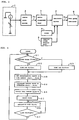
- Fig. 1 is a block diagram of one preferred embodiment of the invention.
- a fuel sensor 1 is of a known type: either a float-equipped potentiometer type or a wire wound resistor type liquid level gauge.
- This liquid level gauge combines a float and a brush integrally, the float floating on the liquid surface, the brush sliding along a resistor element.
- the float changes its position causing the brush to move along the resistor element.
- the moving brush varies the resistance value of the potentiometer or wire wound resistor. If a constant current is allowed to flow through the resistor element, the varying resistance value of the resistor element translates into output voltage variations that are output as detection signals.
- the fuel sensor 1 is not limited to the above-described types. Any other type of fuel sensor may be used.
- the detection signals i.e., voltage signals from the fuel sensor 1 are input to a sensor value reader 2.
- the sensor value reader 2 converts the analog voltage signals to digital form.
- An indicator driver 3 comprises a nonvolatile memory (e.g., ROM) that holds a predetermined program, a CPU that operates according to that program, a RAM, and an I/O unit.
- the indicator driver 3 receives voltage signals in digital form from the sensor value reader 2, time signals from a timer 4, and vehicle speed signals from a vehicle speed judging unit 5, thereby generating liquid level data for indication.
- the indication data thus generated is retained temporarily in the RAM or the like.
- the indication data is transmitted to a fuel level indicator 6 through the I/O unit of the indicator driver 3.
- the timer 4 may be an internal clock of the indicator driver 3 or may be externally provided.
- the vehicle speed judging unit 5 may tap into the capability of vehicle speed judging means used by a speedometer of the vehicle.
- step S1 a check is made to see if a vehicle speed V is at least 4 km/h based on the data from the vehicle speed judging unit 5. If the result of the check in step S1 is negative, step S2 is reached in which a time lag TL is set for one second. If the vehicle speed V is found to be at least 4 km/h, step S3 is reached in which the time lag TL is set for 15 seconds.
- step S1 The rationale for checking in step S1 to see if the vehicle speed V is at least 4 km/h is as follows: if the vehicle is at most traveling as fast as a man walking (about 4 km/h), then the fuel level fluctuations in the vehicle are considered small and germane to precise level indications at short reading intervals (i.e., step S2 is reached in which the time lag TL is set for one second).
- step S4 data Rs detected by the fuel sensor 1 is read from the sensor value reader 2 and retained illustratively in the RAM.
- step S5 the timer 4 is reset.
- step S6 a value based on the detected value Rs above is set as indication data Rin on the fuel level indicator 6. The value on the fuel level indicator 6 is thus updated and replaced by the data Rs.
- the embodiment above permits indications of fuel levels with no time lag at intervals of one second if the vehicle speed is less than 4 km/h, and at intervals of 15 seconds if the vehicle speed is at least 4 km/h. Even if the motorcyclist uprights the vehicle from the parked position (with the side stand extended) to start off in a very short time period, the fuel level measured in the upright position is indicated on the fuel level indicator 6 by the time the vehicle is traveling. This allows the motorcyclist to verify the exact fuel level before going on the road.
- the fuel level indication is updated at intervals of 15 seconds. Fuel level fluctuations caused by the bumpy road surface are thus averaged over time. Fuel levels thus averaged are indicated without recourse to the conventional averaging process based on time-consuming calculations. Because the level indication does not change at inordinately short intervals, the motorcyclist can ascertain the fuel level in an unhurried manner while riding the vehicle.
- the above embodiment sets the time lag TL for one second if the vehicle speed V is less than 4 km/h and for 15 seconds if the speed is at least 4 km/h, this is not limitative of the invention.
- a variation of the embodiment may set the time lag TL for one second when the vehicle speed V is less than 5 km/h and for 15 seconds when the speed is at least 5 km/h.
- Fig. 3 is a block diagram of the second embodiment
- Fig. 4 is a flowchart of steps in which the second embodiment typically operates.
- like reference characters designate like or corresponding parts or steps already shown in Figs. 1 and 2.
- the second embodiment differs from the first embodiment in two points: a rapid averaging unit 7 is interposed between the sensor value reader 2 and the indicator driver 3, and a rapid averaging process constituted by steps S8 and S9 (Fig. 4) is introduced before step S4.
- the rapid averaging unit 7, in step S8 of Fig. 4, receives a limited, small number of data items (Rsi1, ..., Rsi4) in a very short time from among the latest data Rs detected by the sensor value reader 2.
- the rapid averaging unit 7 averages the received data items.
- the most recent four items of the data Rs detected by the sensor value reader 2 are selected every 0.2 seconds, acquired and averaged into an arithmetic mean.
- 2n data items in binary notation are averaged into an arithmetic mean by carrying out as many as "n" shift operations. That is, averaging four data items requires performing only two shift operations. Arithmetic means are thus acquired very rapidly and in a constant time period for each averaging process.
- the rapid averaging unit 7 for averaging four detected data items is to be constituted by hardware, only a single adder and a few shift registers are needed.
- the components are inexpensive when assembled and they operate at a consistent, high speed.
- the second embodiment receives a limited, small number of data items (Rsi1, ..., Rsi4) in a very short time from among the latest data Rs detected by the sensor value reader 2, and averages the data items thus gained. Even if apparently abnormal values are detected, the embodiment with its averaging process is capable of indicating level data minimally affected thereby and with little time lag.
- the rapid averaging unit 7 may be placed interposingly between the fuel sensor 1 and the sensor value reader 2, the averaging unit being constituted by a CR filter having a consistent, very small time constant.
- the CR filter serves rapidly to smooth out variations of the detection signals from the fuel sensor 1.
- the inventive liquid level gauge may be mounted on the vehicle preferably as follows: the vehicle speed judging unit 5, indicator driver 3 and fuel level indicator 6 shown in Fig. 1 are to be housed in a case that accommodates a speedometer, and vehicle speed judging means used by the speedometer is to double as the vehicle speed judging means 5 for fuel level indication.
- the setup allows the indicator driver 3 to be located near the vehicle speed judging means of the speedometer.
- the manner in which the indicator driver 3 is installed here involves shorter wiring, fewer parts and hence lower manufacturing cost than if the indicator driver 3 were housed in an enclosure separate from the case accommodating the speedometer.
- the speedometer is an electrically operated meter, the above arrangement is all the more advantageous in that it places the vehicle speed judging unit, indicator driver and other related parts on the same circuit board for speed indication.
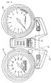
- Fig. 5 shows a typical fuel level gauge mounted on a vehicle. Between a speedometer 10 and a tachometer 20 is a fuel level gauge 30 giving bar graph indications.
- the case of the speedometer 10 contains circuit board whose shape is indicated in broken lines 40.
- a driving circuit (LSI) for the fuel level gauge 30 may be positioned in a given region (e.g., position 41) on the circuit board.
- An object of the present invention is to provide a liquid level gauge for use on a vehicle, the gauge indicating a liquid level on the vehicle in a start-up and in a running state in accordance with requirements designated by a user of the vehicle, the level being indicated with little or no time lag.
- Data detected in analog form by a fuel sensor 1 is converted to digital signals by a sensor value reader 2.
- An indicator driver 3 receives time signals from a timer 4 and speed signals from a vehicle speed sensor 5 and, in a suitably timed manner reflecting the vehicle speed, calculates fuel level data to be indicated based on the digital signals.
- the fuel level data thus calculated is indicated on a fuel level indicator 6.
- the fuel level data is updated at intervals of one second if the vehicle speed is less than 4 km/h and at intervals of 15 seconds if the vehicle speed is at least 4 km/h.
- the indicator driver 3 calculates the fuel level data using the digital signals unmodified or through a rapid averaging process of the signals, whereby the fuel level is indicated with little or no time lag.
Landscapes
- Engineering & Computer Science (AREA)
- Signal Processing (AREA)
- Physics & Mathematics (AREA)
- Fluid Mechanics (AREA)
- General Physics & Mathematics (AREA)
- Measurement Of Levels Of Liquids Or Fluent Solid Materials (AREA)
- Measuring Volume Flow (AREA)
- Instrument Panels (AREA)
- Level Indicators Using A Float (AREA)
Applications Claiming Priority (2)
| Application Number | Priority Date | Filing Date | Title |
|---|---|---|---|
| JP03381098A JP3909618B2 (ja) | 1998-01-30 | 1998-01-30 | 車両用液体残量計 |
| JP3381098 | 1998-01-30 |
Publications (3)
| Publication Number | Publication Date |
|---|---|
| EP0935126A2 true EP0935126A2 (de) | 1999-08-11 |
| EP0935126A3 EP0935126A3 (de) | 1999-08-18 |
| EP0935126B1 EP0935126B1 (de) | 2012-01-18 |
Family
ID=12396845
Family Applications (1)
| Application Number | Title | Priority Date | Filing Date |
|---|---|---|---|
| EP98123924A Expired - Lifetime EP0935126B1 (de) | 1998-01-30 | 1998-12-16 | Flüssigkeitsspiegelanzeiger zum Gebrauch in einem Fahrzeug |
Country Status (3)
| Country | Link |
|---|---|
| US (1) | US6427533B1 (de) |
| EP (1) | EP0935126B1 (de) |
| JP (1) | JP3909618B2 (de) |
Cited By (2)
| Publication number | Priority date | Publication date | Assignee | Title |
|---|---|---|---|---|
| WO2010123437A1 (en) * | 2009-04-22 | 2010-10-28 | Scania Cv Ab | Device and method for detection and display of fuel volume in a tank on a vehicle |
| EP2080998A4 (de) * | 2006-09-26 | 2017-11-22 | Nissan Diesel Motor Co., Ltd. | Wasserstandsmesseinrichtung und wasserstandsmessverfahren |
Families Citing this family (20)
| Publication number | Priority date | Publication date | Assignee | Title |
|---|---|---|---|---|
| US6658933B2 (en) * | 2001-06-22 | 2003-12-09 | Clesse Industries | Fill-level indicator for a liquefied-petroleum-gas tank |
| DE10254421A1 (de) * | 2002-11-21 | 2004-06-03 | Lucas Automotive Gmbh | System zur Beeinflussung der Geschwindigkeit eines Kraftfahrzeuges |
| US7831367B2 (en) * | 2002-11-21 | 2010-11-09 | Lucas Automotive Gmbh | System for influencing the speed of a motor vehicle |
| DE10254424A1 (de) * | 2002-11-21 | 2004-06-03 | Lucas Automotive Gmbh | System zur Beeinflussung der Geschwindigkeit eines Kraftfahrzeuges |
| DE10254423A1 (de) * | 2002-11-21 | 2004-06-03 | Lucas Automotive Gmbh | System zur Beeinflussung der Geschwindigkeit eines Kraftfahrzeuges |
| DE10254394A1 (de) * | 2002-11-21 | 2004-06-03 | Lucas Automotive Gmbh | System zur Beeinflussung der Geschwindigkeit eines Kraftfahrzeuges |
| US7831368B2 (en) * | 2002-11-21 | 2010-11-09 | Lucas Automotive Gmbh | System for influencing the speed of a motor vehicle |
| DE10254402B4 (de) * | 2002-11-21 | 2011-02-17 | Lucas Automotive Gmbh | System zur Beeinflussung der Geschwindigkeit eines Kraftfahrzeuges |
| DE10254403A1 (de) * | 2002-11-21 | 2004-06-03 | Lucas Automotive Gmbh | System zur Beeinflussung der Geschwindigkeit eines Kraftfahrzeuges |
| US7386385B2 (en) * | 2002-11-21 | 2008-06-10 | Lucas Automotive Gmbh | System for recognising the lane-change manoeuver of a motor vehicle |
| US6701784B1 (en) | 2003-01-22 | 2004-03-09 | Aeromotive, Inc. | Carburetor fuel level management system |
| JP2007010467A (ja) * | 2005-06-30 | 2007-01-18 | Nippon Seiki Co Ltd | 液面検出装置 |
| US7711509B2 (en) * | 2007-03-29 | 2010-05-04 | The United States Of America As Represented By The Administrator Of The National Aeronautics And Space Administration | Method of calibrating a fluid-level measurement system |
| JP2009216635A (ja) | 2008-03-12 | 2009-09-24 | Yamaha Motor Co Ltd | 液体残量計の制御装置、液体残量計および車両 |
| US20110079078A1 (en) * | 2009-01-04 | 2011-04-07 | Ho Tan-Hsiung | Fuel Level Sensor |
| JP5643627B2 (ja) * | 2010-12-07 | 2014-12-17 | 住友ゴム工業株式会社 | 水位測定装置 |
| US20150022334A1 (en) * | 2013-07-19 | 2015-01-22 | Deere & Company | Progressive alert system for vehicle reservoir fluid fill level |
| CN104344865B (zh) * | 2013-07-30 | 2017-10-10 | 北汽福田汽车股份有限公司 | 汽车燃油量信号的处理方法和汽车燃油量信号的处理系统 |
| CN113758534B (zh) * | 2021-07-29 | 2024-04-19 | 江铃汽车股份有限公司 | 一种燃料存量显示方法、系统、可读存储介质及车辆 |
| JP7845269B2 (ja) * | 2023-05-10 | 2026-04-14 | トヨタ自動車株式会社 | 車両の制御装置 |
Family Cites Families (11)
| Publication number | Priority date | Publication date | Assignee | Title |
|---|---|---|---|---|
| US4179740A (en) * | 1977-09-02 | 1979-12-18 | Malin John R | Vehicle performance analyzer |
| JPS6041288B2 (ja) * | 1980-05-03 | 1985-09-14 | 株式会社デンソー | 車両用残燃料量表示装置 |
| US4313114A (en) * | 1980-05-30 | 1982-01-26 | Leupold & Stevens, Inc. | Liquid level recorder apparatus and method for storing level differences in memory |
| US4444051A (en) * | 1981-03-18 | 1984-04-24 | Nissan Motor Company, Limited | Electronic liquid level gauge |
| JPS57211514A (en) * | 1981-06-23 | 1982-12-25 | Mitsubishi Electric Corp | Fuel level gauge for automobile |
| US4470296A (en) * | 1981-12-28 | 1984-09-11 | Nissan Motor Company, Limited | Fuel gauge for an automotive vehicle |
| JPS601567A (ja) | 1983-06-17 | 1985-01-07 | Victor Co Of Japan Ltd | 回転方向検出装置 |
| FR2601769B2 (fr) * | 1986-03-13 | 1994-03-25 | Veglia | Dispositif electronique d'interface entre un capteur et un afficheur |
| IT1206845B (it) * | 1987-01-16 | 1989-05-11 | Fiat Auto Spa | Dispositivo per la misurazione del livello di carburante presente nel serbatoio di un autoveicolo e relativo procedimento di impiego |
| JPH01257222A (ja) * | 1987-04-03 | 1989-10-13 | Yazaki Corp | 電子式燃料残量計 |
| US5321633A (en) * | 1990-04-10 | 1994-06-14 | Yazaki Corporation | Heat radiating type liquid level sensing system and the method therefor |
-
1998
- 1998-01-30 JP JP03381098A patent/JP3909618B2/ja not_active Expired - Fee Related
- 1998-12-16 EP EP98123924A patent/EP0935126B1/de not_active Expired - Lifetime
-
1999
- 1999-01-29 US US09/239,993 patent/US6427533B1/en not_active Expired - Fee Related
Cited By (2)
| Publication number | Priority date | Publication date | Assignee | Title |
|---|---|---|---|---|
| EP2080998A4 (de) * | 2006-09-26 | 2017-11-22 | Nissan Diesel Motor Co., Ltd. | Wasserstandsmesseinrichtung und wasserstandsmessverfahren |
| WO2010123437A1 (en) * | 2009-04-22 | 2010-10-28 | Scania Cv Ab | Device and method for detection and display of fuel volume in a tank on a vehicle |
Also Published As
| Publication number | Publication date |
|---|---|
| JPH11218434A (ja) | 1999-08-10 |
| EP0935126B1 (de) | 2012-01-18 |
| EP0935126A3 (de) | 1999-08-18 |
| JP3909618B2 (ja) | 2007-04-25 |
| US6427533B1 (en) | 2002-08-06 |
Similar Documents
| Publication | Publication Date | Title |
|---|---|---|
| EP0935126B1 (de) | Flüssigkeitsspiegelanzeiger zum Gebrauch in einem Fahrzeug | |
| US5826459A (en) | Remaining fuel amount measuring apparatus for a fuel tank | |
| US6374190B2 (en) | Method for calibrating an angle sensor and navigation system having an angle sensor | |
| US6666084B2 (en) | Method for determining the fluid level of a tank in motor vehicles | |
| US4470296A (en) | Fuel gauge for an automotive vehicle | |
| US4564905A (en) | Trip computer for vehicles | |
| US5626052A (en) | Smart fuel tank module | |
| US5072615A (en) | Apparatus and method for gauging the amount of fuel in a vehicle fuel tank subject to tilt | |
| US20090105975A1 (en) | Method and circuit arrangement for measuring a capacitance | |
| US4640127A (en) | Electrothermal measurement of levels compensated for ambient temperature | |
| US5913911A (en) | Method and apparatus for concentrating signals | |
| GB2054162A (en) | Determining the reserve of a motor vehicle operating liquid | |
| EP0733879A1 (de) | Einrichtung zur Messung von Höhe | |
| US4811596A (en) | Arrangement for tank content measurement of an operating-medium tank of a vehicle | |
| JP2000356657A (ja) | 電圧計測システム | |
| RU2163005C2 (ru) | Способ измерения количества топлива в баке автомобиля | |
| WO1999063215A1 (en) | Method and device for calculating cruising range | |
| EP0854355A1 (de) | Füllstandsniveaumesserschnittstelle mit dynamischem Offset | |
| JPH0340326B2 (de) | ||
| JPS60170724A (ja) | 燃料残量計 | |
| JPS5895230A (ja) | 電子式温度測定方法及び装置 | |
| JPS59135321A (ja) | 移動体のための液量計 | |
| WO2001038839A1 (en) | Apparatus for performing a temperature measurement | |
| EP4317931B1 (de) | Fahrradleistungsmesser | |
| JPS5931415A (ja) | 車両用燃料残量計測装置 |
Legal Events
| Date | Code | Title | Description |
|---|---|---|---|
| PUAI | Public reference made under article 153(3) epc to a published international application that has entered the european phase |
Free format text: ORIGINAL CODE: 0009012 |
|
| PUAL | Search report despatched |
Free format text: ORIGINAL CODE: 0009013 |
|
| AK | Designated contracting states |
Kind code of ref document: A2 Designated state(s): DE FR IT |
|
| AX | Request for extension of the european patent |
Free format text: AL;LT;LV;MK;RO;SI |
|
| AK | Designated contracting states |
Kind code of ref document: A3 Designated state(s): AT BE CH CY DE DK ES FI FR GB GR IE IT LI LU MC NL PT SE |
|
| AX | Request for extension of the european patent |
Free format text: AL;LT;LV;MK;RO;SI |
|
| 17P | Request for examination filed |
Effective date: 19991015 |
|
| AKX | Designation fees paid |
Free format text: DE FR IT |
|
| 17Q | First examination report despatched |
Effective date: 20060627 |
|
| GRAP | Despatch of communication of intention to grant a patent |
Free format text: ORIGINAL CODE: EPIDOSNIGR1 |
|
| GRAS | Grant fee paid |
Free format text: ORIGINAL CODE: EPIDOSNIGR3 |
|
| GRAA | (expected) grant |
Free format text: ORIGINAL CODE: 0009210 |
|
| AK | Designated contracting states |
Kind code of ref document: B1 Designated state(s): DE FR IT |
|
| RIN1 | Information on inventor provided before grant (corrected) |
Inventor name: YOSHIDA, SUSUMUC/O K.K. HONDA GIJUTSU KENKYUSHO |
|
| RIN2 | Information on inventor provided after grant (corrected) |
Inventor name: YOSHIDA, SUSUMUC/O KABUSHIKI KAISHA HONDA GIJUTSU |
|
| REG | Reference to a national code |
Ref country code: DE Ref legal event code: R096 Ref document number: 69842570 Country of ref document: DE Effective date: 20120322 |
|
| PLBE | No opposition filed within time limit |
Free format text: ORIGINAL CODE: 0009261 |
|
| STAA | Information on the status of an ep patent application or granted ep patent |
Free format text: STATUS: NO OPPOSITION FILED WITHIN TIME LIMIT |
|
| 26N | No opposition filed |
Effective date: 20121019 |
|
| PGFP | Annual fee paid to national office [announced via postgrant information from national office to epo] |
Ref country code: DE Payment date: 20121213 Year of fee payment: 15 |
|
| REG | Reference to a national code |
Ref country code: DE Ref legal event code: R097 Ref document number: 69842570 Country of ref document: DE Effective date: 20121019 |
|
| PGFP | Annual fee paid to national office [announced via postgrant information from national office to epo] |
Ref country code: IT Payment date: 20121214 Year of fee payment: 15 |
|
| PGFP | Annual fee paid to national office [announced via postgrant information from national office to epo] |
Ref country code: FR Payment date: 20130107 Year of fee payment: 15 |
|
| REG | Reference to a national code |
Ref country code: DE Ref legal event code: R119 Ref document number: 69842570 Country of ref document: DE |
|
| REG | Reference to a national code |
Ref country code: FR Ref legal event code: ST Effective date: 20140829 |
|
| REG | Reference to a national code |
Ref country code: DE Ref legal event code: R119 Ref document number: 69842570 Country of ref document: DE Effective date: 20140701 |
|
| PG25 | Lapsed in a contracting state [announced via postgrant information from national office to epo] |
Ref country code: DE Free format text: LAPSE BECAUSE OF NON-PAYMENT OF DUE FEES Effective date: 20140701 |
|
| PG25 | Lapsed in a contracting state [announced via postgrant information from national office to epo] |
Ref country code: FR Free format text: LAPSE BECAUSE OF NON-PAYMENT OF DUE FEES Effective date: 20131231 |
|
| PG25 | Lapsed in a contracting state [announced via postgrant information from national office to epo] |
Ref country code: IT Free format text: LAPSE BECAUSE OF NON-PAYMENT OF DUE FEES Effective date: 20131231 |
|
| PG25 | Lapsed in a contracting state [announced via postgrant information from national office to epo] |
Ref country code: IT Free format text: LAPSE BECAUSE OF NON-PAYMENT OF DUE FEES Effective date: 20131216 |