EP0935265A2 - Durch thermische Zerstäubung beschichtetes Substrat zur Verwendung in einer elektrischen Energiespeicheranordnung und Herstellungsverfahren - Google Patents
Durch thermische Zerstäubung beschichtetes Substrat zur Verwendung in einer elektrischen Energiespeicheranordnung und Herstellungsverfahren Download PDFInfo
- Publication number
- EP0935265A2 EP0935265A2 EP98309396A EP98309396A EP0935265A2 EP 0935265 A2 EP0935265 A2 EP 0935265A2 EP 98309396 A EP98309396 A EP 98309396A EP 98309396 A EP98309396 A EP 98309396A EP 0935265 A2 EP0935265 A2 EP 0935265A2
- Authority
- EP
- European Patent Office
- Prior art keywords
- substrate
- metal
- coating
- coated substrate
- capacitor
- Prior art date
- Legal status (The legal status is an assumption and is not a legal conclusion. Google has not performed a legal analysis and makes no representation as to the accuracy of the status listed.)
- Withdrawn
Links
Images

Classifications
-
- H—ELECTRICITY
- H01—ELECTRIC ELEMENTS
- H01G—CAPACITORS; CAPACITORS, RECTIFIERS, DETECTORS, SWITCHING DEVICES, LIGHT-SENSITIVE OR TEMPERATURE-SENSITIVE DEVICES OF THE ELECTROLYTIC TYPE
- H01G9/00—Electrolytic capacitors, rectifiers, detectors, switching devices, light-sensitive or temperature-sensitive devices; Processes of their manufacture
- H01G9/004—Details
- H01G9/04—Electrodes or formation of dielectric layers thereon
- H01G9/042—Electrodes or formation of dielectric layers thereon characterised by the material
-
- H—ELECTRICITY
- H01—ELECTRIC ELEMENTS
- H01G—CAPACITORS; CAPACITORS, RECTIFIERS, DETECTORS, SWITCHING DEVICES, LIGHT-SENSITIVE OR TEMPERATURE-SENSITIVE DEVICES OF THE ELECTROLYTIC TYPE
- H01G11/00—Hybrid capacitors, i.e. capacitors having different positive and negative electrodes; Electric double-layer [EDL] capacitors; Processes for the manufacture thereof or of parts thereof
- H01G11/02—Hybrid capacitors, i.e. capacitors having different positive and negative electrodes; Electric double-layer [EDL] capacitors; Processes for the manufacture thereof or of parts thereof using combined reduction-oxidation reactions, e.g. redox arrangement or solion
-
- H—ELECTRICITY
- H01—ELECTRIC ELEMENTS
- H01G—CAPACITORS; CAPACITORS, RECTIFIERS, DETECTORS, SWITCHING DEVICES, LIGHT-SENSITIVE OR TEMPERATURE-SENSITIVE DEVICES OF THE ELECTROLYTIC TYPE
- H01G11/00—Hybrid capacitors, i.e. capacitors having different positive and negative electrodes; Electric double-layer [EDL] capacitors; Processes for the manufacture thereof or of parts thereof
- H01G11/22—Electrodes
- H01G11/26—Electrodes characterised by their structure, e.g. multi-layered, porosity or surface features
-
- H—ELECTRICITY
- H01—ELECTRIC ELEMENTS
- H01G—CAPACITORS; CAPACITORS, RECTIFIERS, DETECTORS, SWITCHING DEVICES, LIGHT-SENSITIVE OR TEMPERATURE-SENSITIVE DEVICES OF THE ELECTROLYTIC TYPE
- H01G11/00—Hybrid capacitors, i.e. capacitors having different positive and negative electrodes; Electric double-layer [EDL] capacitors; Processes for the manufacture thereof or of parts thereof
- H01G11/22—Electrodes
- H01G11/30—Electrodes characterised by their material
- H01G11/46—Metal oxides
-
- Y—GENERAL TAGGING OF NEW TECHNOLOGICAL DEVELOPMENTS; GENERAL TAGGING OF CROSS-SECTIONAL TECHNOLOGIES SPANNING OVER SEVERAL SECTIONS OF THE IPC; TECHNICAL SUBJECTS COVERED BY FORMER USPC CROSS-REFERENCE ART COLLECTIONS [XRACs] AND DIGESTS
- Y02—TECHNOLOGIES OR APPLICATIONS FOR MITIGATION OR ADAPTATION AGAINST CLIMATE CHANGE
- Y02E—REDUCTION OF GREENHOUSE GAS [GHG] EMISSIONS, RELATED TO ENERGY GENERATION, TRANSMISSION OR DISTRIBUTION
- Y02E60/00—Enabling technologies; Technologies with a potential or indirect contribution to GHG emissions mitigation
- Y02E60/13—Energy storage using capacitors
Definitions
- the present invention generally relates to an electrical energy storage device, and more particularly, to a substrate provided with a thermal spray generated pseudocapacitive coating for incorporation into an electrical energy storage device. Still more particularly, the present invention provides a thermal spray generated porous, high surface area metal oxide, metal nitride, metal carbon nitride or metal carbide coating on a conductive foil for use in a capacitor, an electrochemical cell and the like. Thermal spray processes include both chemical combustion spraying and electric heating spraying, using both wire and powder forms of active materials.
- a capacitor electrode generally includes a substrate of a conductive metal such as titanium or tantalum provided with a semiconductive or pseudocapacitive oxide coating, nitride coating, carbon nitride coating, or carbide coating.
- a conductive metal such as titanium or tantalum provided with a semiconductive or pseudocapacitive oxide coating, nitride coating, carbon nitride coating, or carbide coating.
- Commonly used techniques include dipping and pressurized air atomization spraying of the active material onto the substrate. Capacitance values for electrodes made by dipping, pressurized air atomization spraying and sputtering are lower in specific capacitance. Sol-gel deposition is another conventional method of coating the substrate. Additionally, it is exceptionally difficult to accurately control the coating morphology due to the controllability and repeatability of the various prior art techniques, which directly impacts capacitance.
- electrochemical capacitors provide much higher energy storage densities than conventional capacitors, there is a need to further increase the energy storage capacity of such devices.
- One way of accomplishing this is to provide electrodes which can be manufactured with repeatably controllable morphology according to the present invention, in turn benefiting repeatably increased effective surface areas.
- the coating according to the present invention is formed by thermal spraying a highly porous, high surface area pseudocapacitive film of ruthenium oxide onto the substrate.
- the present invention therefore, describes the thermal spray deposition of a metal-containing pseudocapacitive active material onto a conductive substrate.
- Thermal spraying is defined as any process in which particles are heated to a molten or plastic state and propelled onto a substrate to form a coating thereon. This includes chemical combustion spraying and electrical heating spraying, using both wire and powder processes.
- the present invention includes heating and projecting particles of an active material onto a prepared electrode substrate using a thermal spraying process to thereby provide an electrode component for an energy storage device such as a capacitor or an electrochemical cell and the like.
- Thermal spray coatings of electrode active material usually exhibit two common features in the as-deposited condition, a sandpaper-like surface finish and a structure with inherent porosity.
- thermal spray coating a pseudocapacitive active material onto a substrate provides a relatively low density, porous structure. This advantageously benefits the specific surface area which in turn benefits energy storage capacity and energy storage density and ultimately discharge efficiency. Therefore, the capacitance of pseudocapacitors can be further improved by using an electrode comprising a conductive substrate coated with a thermal spray deposited porous film to increase the surface area of the electrode.
- thermal spraying processes may be classified into two groups namely, chemical combustion spraying processes and electric heating spraying processes.
- Chemical combustion spraying processes include powder flame spraying, wire/rod flame spraying, high velocity oxygen fuel flame spraying and detonation/explosive flame spraying.
- Electrical heating spraying processes include electric-arc or twin-wire arc spraying and plasma spraying.
- the two groups of spraying processes are generally delineated by the methods used to generate heat to plasticize and/or atomize the pseudocapacitive active material. In general, flame sprayed coatings exhibit lower bond strengths, higher porosity, a narrower working temperature range and a higher heat transmittal to the substrate than electric-arc and plasma sprayed coatings.
- the pseudocapacitive material begins as a powder, solution or a wire of the active material.
- the powder, solution or wire form of the pseudocapactive material intended to be thermal spray contacted to the substrate preferably contains molar proportions of the active material in substantially the stoichiometric ratio needed to form the desired coating.
- Powder flame spraying involves the use of a powder flame spray gun consisting of a high-capacity, oxygen-fuel gas torch and a hopper containing the pseudocapacitive active material in powder or particulate form.
- a small amount of oxygen from the gas supply is diverted to carry the powdered active material by aspiration into the oxygen- fuel gas flame where the powder is heated and propelled by the exhaust flame onto the substrate workpiece.
- the fuel gas is usually acetylene or hydrogen and temperatures in the range of about 3,000°F to 4,500°F are typically obtained.
- Particle velocities are on the order of about 80 to about 100 feet per second.
- the coatings produced generally have low bond strength, high porosity and low overall cohesive strength.
- Wire/rod flame spraying utilizes a wire of the pseudocapacative active material that is continuously fed into an oxy-acetylene flame where the wire is melted and atomized by an auxiliary stream of compressed air and then deposited as the coating of active material on the substrate. This process also lends itself to use of plastic tubes filled with the pseudocapacitive active material in a powder form.
- High velocity, oxygen fuel flame spraying is a continuous combustion process that produces exit gas velocities estimated to be about 4,000 to about 5,000 feet per second and particle speeds of about 1,800 to about 2,600 feet per second. This is accomplished by burning a fuel gas (usually propylene) with oxygen under high pressure (60 to 90 psi) in an internal combustion chamber. Hot exhaust gases are discharged from the combustion chamber through exhaust ports and thereafter expanded in an extending nozzle. Pseudocapacitive active powder or solution is fed axially into the extending nozzle and confined by the exhaust gas stream until the active material exits in a thin high speed jet to produce coatings which are more dense than those produced by powder flame spraying.
- a fuel gas usually propylene
- Hot exhaust gases are discharged from the combustion chamber through exhaust ports and thereafter expanded in an extending nozzle.
- Pseudocapacitive active powder or solution is fed axially into the extending nozzle and confined by the exhaust gas stream until the active material exits in a thin high speed jet to produce
- a modified flame spraying process is referred to as a flame spray and fuse process.
- the pseudocapacitive component is prepared by coating a pseudocapacitive active material onto the substrate using one of the above described flame spraying processes followed by a fusing step.
- Fusing is accomplished by one of several techniques such as flame or torch, induction, or in vacuum, inert or hydrogen furnaces. Typical heating times for oxides may range from about one-half hour to about six hours.
- the coated substrate is then heated to a temperature of about 100°C to 300°C, preferably about 250°C for about one hour, followed by a further heating at a temperature of about 250°C to 400°C, preferably about 300°C for about two hours. This is immediately followed by a further heating at a temperature of about 350°C to about 800°C, preferably about 400°C for about two hours and fifteen minutes. While this three step heating protocol is preferred for fusing the pseudocapacitive material to the substrate, it is contemplated by the scope of the present invention that fusing may take place by a two step or a four step or more heating protocol.
- the temperature is slowly and steadily ramped up, for example, at about 1°C minute, preferably about 6°C/min. until the temperature reaches a temperature of about 100°C to 800°C, preferably about 400°C where the temperature is maintained for a time sufficient to allow the pseudocapacitive material to completely fuse to the substrate.
- the heated and coated substrate is allowed to slowly cool to ambient temperature.
- the substrate material for the capacitor electrode needs to be able to withstand this temperature range.
- the pseudocapacitor metal may be contacted to a substrate heated to a temperature to instantaneously fuse the pseudocapacitive material thereto.
- the substrate is at a temperature of about 100°C to 800°C, preferably about 400°C, as the pseudocapacitive material is deposited on the substrate.
- the heated and coated substrate is allowed to slowly cool to ambient temperature.
- the detonation/explosive flame spraying process uses detonation waves from repeated explosions of oxy-acetylene gas mixtures to accelerate the powered pseudocapacitive active material onto the substrate. Particulate velocities on the order of 2,400 feet per second are achieved and the pseudocapacitive active material coating deposits are extremely strong, hard, dense and tightly bonded.
- the other type of thermal spraying useful for coating a substrate with a pseudocapacitive coating is electrical heating thermal spraying.
- One such electrical heating thermal spraying process is referred to as the electric-arc or twin-wire arc spraying process and uses two consumable wires of pseudocapacitive active material.
- the wires are initially insulated from each other and simultaneously advanced to meet at a focal point in an atomizing gas stream.
- Contact tips serve to precisely guide the wires and to provide good electrical contact between the moving wires and power cables. Heating is provided by means of a direct current potential difference applied across the wires to form an arc that melts the intersecting wires.
- a jet of gas shears off molten droplets of the melted pseudocapacitive active material and propels this material onto the substrate.
- Sprayed pseudocapacitive active material particle sizes can be changed with different atomizing heads and wire intersection angles.
- Direct current is supplied at potentials of about 18 to 40 volts, depending on the pseudocapacitive active material to be sprayed; the size of particle spray increasing as the arc gap is lengthened with rise in voltage. Voltage is therefore maintained at a higher level consistent with arc stability to provide larger particles and a rough, porous coating that is suitable for chemisorption of the ions produced by oxidation of the counter-electrode. Because high arc temperatures (in excess of about 7,240°F) are typically encountered, twin-wire arc sprayed coatings have high bond and cohesive strength.
- Plasma spraying involves the passage of a gas or a gas mixture through a direct current arc maintained in a chamber between a coaxially aligned cathode and water-cooled anode.
- the arc is initiated with a high frequency discharge that partially ionises the gas to create a plasma having temperatures that may exceed 30,000°F.
- the plasma flux exits the gun through a hole in the anode which acts as a nozzle and the temperature of the expelled plasma effluent falls rapidly with distance.
- Powdered pseudocapacitive active material feed-stock is introduced into the hot gaseous effluent at an appropriate point and propelled to the workpiece by the high velocity stream.
- the heat content, temperature and velocity of the plasma gas are controlled by regulating arc current, gas flow rate, the type and mixture ratio of gases and by the anode/cathode configuration.
- the substrate to be contacted with the pseudocapacitive coating preferably consists of a conductive metal such as titanium, molybdenum, tantalum, niobium, cobalt, nickel, stainless steel, tungsten, platinum, palladium, gold, silver, copper, chromium, vanadium, aluminum, zirconium, hafnium, zinc and iron, and the like, and mixtures and alloys thereof.
- a conductive metal such as titanium, molybdenum, tantalum, niobium, cobalt, nickel, stainless steel, tungsten, platinum, palladium, gold, silver, copper, chromium, vanadium, aluminum, zirconium, hafnium, zinc and iron, and the like, and mixtures and alloys thereof.
- substrate surface cleanliness is very important in all coating systems, especially in pseudocapacitive coatings. In that respect, it is required that the substrate surface remain uncontaminated by lubricants from handling equipment or body oils from hands and the like.
- Substrate cleaning includes chemical means such as conventional degreasing treatments using aqueous and nonaqueous solutions, as well known to those skilled in the art. Plasma cleaning is also contemplated by the scope of the present invention.
- the substrate to be coated may be roughened by chemical means, for example, by contacting the substrate with hydrofluoric acid and/or hydrochloric acid containing ammonium bromide and methanol and the like, by plasma etching, and by mechanical means such as scraping, machining, wire brushing, rough threading, grit blasting, a combination of rough threading then grit blasting and abrading such as by contacting the substrate with Scotch-BriteTM abrasive sheets manufactured by 3M.
- the electrical conductivity of the substrate is improved prior to coating.
- Metal and metal alloys have a native oxide present on their surface. This is a resistive layer and hence, if the material is to be used as a substrate for a capacitor electrode, the oxide is preferably removed or made electrically conductive prior to deposition of a pseudocapacitive coating thereon.
- various techniques can be employed. One is shown and described in U.S. Patent No. 5,098,485 to Evans, the disclosure of which is hereby incorporated by reference.
- a preferred method for improving the conductivity of the substrate includes depositing a minor amount of a metal or metals from Groups IA, IVA and VIIIA of the Periodic Table of Elements onto the substrate. Aluminum, manganese, nickel and copper are also suitable for this purpose.
- the deposited metal is then "intermixed" with the substrate material by, for example, a high energy ion beam or a laser beam directed towards the deposited surface.
- These substrate treating processes are performed at relatively low temperatures to prevent substrate degradation and deformation. Additionally, these treating processes can be used to passivate the substrate from further chemical reaction while still providing adequate electrical conductivity.
- the thermal spray coated substrate of the present invention consists essentially of a porous film coating (not shown) including the oxide of a first metal, the nitride of the first metal, the carbon nitride of the first metal and/or the carbide of the first metal, the oxide, nitride, carbon nitride and carbide of the first metal having pseudocapacitive properties.
- the first metal is preferably selected from the group consisting of ruthenium, cobalt, manganese, molybdenum, tungsten, tantalum, iron, niobium, iridium, titanium, zirconium, hafnium, rhodium, vanadium, osmium, palladium, platinum, and nickel.
- the deposited mixture can include an anhydrous nitrate or an anhydrous chloride of the metal.
- the porous coating may also include a second or more metals.
- the second metal is in the form of an oxide, a nitride, a carbon nitride or a carbide, and is not essential to the intended use of the coated foil as a capacitor electrode and the like.
- the second metal is different than the first metal and is selected from one or more of the group consisting of tantalum, titanium, nickel, iridium, platinum, palladium, gold, silver, cobalt, molybdenum, ruthenium, manganese, tungsten, iron, zirconium, hafnium, rhodium, vanadium, osmium, and niobium.
- the porous coating includes anhydrous oxides of ruthenium and tantalum.
- the resulting porous coating whether it be of an oxide, a nitride, a carbon nitride or a carbide, have a thickness of from about a few hundred Angstroms to about 0.1 millimeters or more.
- the porous coating has an internal surface area of about 1 m 2 /gram to about 1,500 m 2 /gram, and the majority of the particles have diameters less than about 50 microns.
- the thickness of the substrate is typically in the range of about 0.001 millimeters to about 2 millimeter and preferably about 0.1 millimeters.
- the substrate may be of substantially any size or shape, and it may be stationary or movable. Because of the speed of the coating process, the substrate may be moved across the thermally generated spray to have any or all of its surface contacted with the pseudocapacitive coating.
- the substrate is preferably moved in a plane which is substantially normal to the direction of flow of the thermally generated spray. In another embodiment, the substrate is moved stepwise along a predetermined path to coat the substrate only at certain predetermined areas.
- rotary substrate motion is utilized to expose the surface of a complex-shaped article to the thermally generated spray. This rotary substrate motion may be effected by conventional means.
- the process of the present invention provides for coating the substrate at a deposition rate of from about 0.01 to about 10 microns per minute and, preferably, from about 0.1 to about 1.0 microns per minute.
- the thickness of the film coated upon the substrate may be determined by means well known to those skilled in the art.
- the as-deposited coating layer consists of non-uniform grains.
- the term "as-deposited” refers to the film prior to any subsequent processing which the coated substrate may undergo after being contacted with the thermally generated spray.
- the fusing step following the previously discussed flame spraying process is a subsequent processing step of the as -deposited active material.
- the thermal spraying processes of the present invention are conducted under substantially atmospheric pressure conditions.
- substantially atmospheric refers to a pressure of at least about 600 millimeters of mercury and, preferably, from about 600 to about 1,000 millimeters of mercury.
- atmospheric pressure at sea level is 760 millimeters of mercury.
- a thermal spray coated substrate according to the present invention is useful as an electrode in various types of electrochemical capacitors including unipolar and bipolar designs, and capacitors having a spirally wound configuration.
- Fig. 1 there is shown a schematic representation of a typical unipolar electrochemical capacitor 10 having spaced apart electrodes 12 and 14.
- One of the electrodes, for example, electrode 12 serves as the cathode electrode and comprises a thermal spray generated coating 16A of pseudocapacitive material provided on a conductive plate 18A according to the present invention.
- a porous ruthenium oxide film is provided on plate 18A which is of a conductive material such as tantalum.
- the relative thicknesses of the plate 18A and the pseudocapacitive coating 16A thereon are distorted for illustrative purposes. As previously described, the plate is about 0.01 millimeters to about 1 millimeter in thickness and the coating 16A is in the range of about a few hundred Angstroms to about 0.1 millimeters thick.
- the other electrode 14 serves as the anode and is of a similar pseudocapacitive material 16B contacted to a conductive substrate 18B, as in electrode 12.
- the cathode electrode 12 and the anode electrode 14 are separated from each other by an ion permeable membrane 20 serving as a separator.
- the electrodes 12 and 14 are maintained in the spaced apart relationship shown by opposed insulating members 22 and 24 such as of an elastomeric material contacting end portions of the plates 18A, 18B.
- the end plate portions typically are not coated with a pseudocapacitive material.
- An electrolyte (not shown), which may be any of the conventional electrolytes used in electrolytic capacitors, such as a solution of sulfuric acid, potassium hydroxide, or an ammonium salt is provided between and in contact with the cathode and anode electrodes 12 and 14.
- Electrodes 12 and 14 are easily attached to the electrodes 12 and 14 before, during, or after assembly of the capacitor and the thusly constructed unipolar capacitor configuration is housed in a suitable casing, or the conductive plates along with the insulating members can serve as the capacitor housing.
- Fig. 2 is a schematic representation of a typical bipolar electrochemical capacitor 30 comprising a plurality of capacitor units 32 arranged and interconnected serially.
- Each unit 32 includes bipolar conductive substrate 34.
- Porous pseudocapacitive coatings 36 and 38 are provided on the opposite sides of substrate 34 according to the present thermal spray coating processes. For exaxple, a porous coating of ruthenium oxide film is deposited onto both sides of substrate 34. Again, the thickness of the porous coatings 36 and 30 is distorted for illustrative purposes.
- the units 32 are then assembled into the bipolar capacitor configuration on opposite sides of an intermediate separator 40. Elastomeric insulating members 42 and 44 are provided to maintain the units 32 in their spaced apart relationship.
- insulators 42, 44 Materials other than elastomeric materials may be apparent to those skilled in the art for use as insulators 42, 44.
- a plurality of individual electrochemical capacitor units 32 are interconnected in series to provide the bipolar configuration.
- the serial arrangement of units 32 is completed at the terminal ends thereof by end plates (not shown), as is well known to those skilled in the art.
- an electrolyte (not shown) is provided between and in contact with the coatings 36, 38 of the capacitor 30.
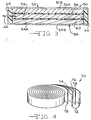
- Fig. 3 shows a schematic representation of an electrolytic capacitor 50 having spaced apart cathode electrodes 52, 54, each comprising a respective thermal spray deposited coating 52A, 54A of pseudocapacitive material provided on a conductive plate 52B, 54B according to the present invention.
- the thickness of the porous coatings 52A, 54A is enlarged for clarity.
- the counter electrode or anode 56 is intermediate the cathodes 52, 54 with separators 58, 60 preventing contact between the electrodes.
- the anode 56 is of a conventional sintered metal, preferably in a porous form.
- Suitable anode metals are selected from the group consisting of titanium, aluminum, niobium, zirconium, hafnium, tungsten, molybdenum, vanadium, silicon, germanium and tantalum contacted to a terminal pin 62.
- the hybrid capacitor 50 is completed by insulating members 64, 66 contacting end portions of the cathode plates. While not shown, an electrolyte is provided to activate the electrodes 52, 54 and 56.
- Fig. 4 is a schematic drawing of another embodiment of a jelly roll configured capacitor 70, which can be manufactured, in part, by one of the thermal spray coating processes according to the present invention.
- Capacitor 70 has a plurality of capacitor units 72, each comprising a conductive substrate provided with a thermal spray generated pseudocapacitive coating 74, 76 on the opposed sides thereof.
- the coatings can be, for example of ruthenium oxide, separated from immediately adjacent cells by an intermediate separator 78.
- This structure is then wound in a jelly roll fashion and housed in a suitable casing. Leads are contacted to the anode and cathode electrodes and the capacitor is activated by an electrolyte in the customary manner.
- the particle size of the active material can be smaller than that produced by the various prior art techniques previously discussed. This results in greater control over the manufacturing process in terms of controlling the coating morphology from one production run to the next. Furthermore, the use of a thermal spray deposited coating on a conductive substrate is believed to form an electrode for a capacitor according to the present invention that provides a higher surface area coating than that obtainable by the prior art, and thus a higher capacitance electrode.
- thermal spraying a pseudocapacitive active material represents a viable and alternate method of producing a capacitor electrode for incorporation into an electrical energy storage device such as a capacitor, an electrochemical cell and the like.
Landscapes
- Engineering & Computer Science (AREA)
- Power Engineering (AREA)
- Microelectronics & Electronic Packaging (AREA)
- Chemical & Material Sciences (AREA)
- Materials Engineering (AREA)
- Chemical Kinetics & Catalysis (AREA)
- Electric Double-Layer Capacitors Or The Like (AREA)
- Coating By Spraying Or Casting (AREA)
- Manufacturing Of Micro-Capsules (AREA)
- Chemical Vapour Deposition (AREA)
Applications Claiming Priority (2)
| Application Number | Priority Date | Filing Date | Title |
|---|---|---|---|
| US2071798A | 1998-02-09 | 1998-02-09 | |
| US20717 | 1998-02-09 |
Publications (2)
| Publication Number | Publication Date |
|---|---|
| EP0935265A2 true EP0935265A2 (de) | 1999-08-11 |
| EP0935265A3 EP0935265A3 (de) | 2002-06-12 |
Family
ID=21800163
Family Applications (1)
| Application Number | Title | Priority Date | Filing Date |
|---|---|---|---|
| EP98309396A Withdrawn EP0935265A3 (de) | 1998-02-09 | 1998-11-17 | Durch thermische Zerstäubung beschichtetes Substrat zur Verwendung in einer elektrischen Energiespeicheranordnung und Herstellungsverfahren |
Country Status (4)
| Country | Link |
|---|---|
| US (1) | US6455108B1 (de) |
| EP (1) | EP0935265A3 (de) |
| JP (1) | JPH11312630A (de) |
| AU (1) | AU754373B2 (de) |
Cited By (3)
| Publication number | Priority date | Publication date | Assignee | Title |
|---|---|---|---|---|
| EP1487034A3 (de) * | 2003-06-12 | 2007-03-28 | Nissan Motor Co., Ltd. | Bipolare Batterie und zugehöriges Verfahren |
| EP1800321A4 (de) * | 2004-10-08 | 2010-05-05 | Showa Denko Kk | Elektrodenblatt für condensatoren, herstellungsverfahren dafür und elektrolytcondensator |
| CN101996695B (zh) * | 2009-08-18 | 2013-09-11 | 汉民科技股份有限公司 | 耐高压电极结构及其制造方法 |
Families Citing this family (37)
| Publication number | Priority date | Publication date | Assignee | Title |
|---|---|---|---|---|
| US6784139B1 (en) * | 2000-07-10 | 2004-08-31 | Applied Thin Films, Inc. | Conductive and robust nitride buffer layers on biaxially textured substrates |
| US6777374B2 (en) * | 2000-07-18 | 2004-08-17 | The United States Of America As Represented By The Environmental Protection Agency | Process for photo-induced selective oxidation of organic chemicals to alcohols, ketones and aldehydes using flame deposited nano-structured photocatalyst |
| US7005214B2 (en) * | 2001-11-02 | 2006-02-28 | Wilson Greatbatch Technologies, Inc. | Noble metals coated on titanium current collectors for use in nonaqueous Li/CFx cells |
| JP4039862B2 (ja) * | 2002-02-07 | 2008-01-30 | 松下電器産業株式会社 | 電極材料の製造方法 |
| EP1547973A4 (de) * | 2002-09-05 | 2008-07-30 | Nat Inst Of Advanced Ind Scien | FEINES KOHLENSTOFFPULVER MIT METALLOXID-, METALLNITRID- ODER METALLCARBIDBESCHICHTUNG, HERSTELLUNGSVERFAHREN DAF R UND SUPERKONDENSATOR UND SEKUNDûRBATTERIE UNTER VERWENDUNG DES FEINEN KOHLENSTOFFPULVERS |
| JP4000075B2 (ja) * | 2003-02-27 | 2007-10-31 | 株式会社東芝 | ロータの補修方法 |
| JP2005223155A (ja) * | 2004-02-05 | 2005-08-18 | Companhia Brasileira De Metalurgia & Mineracao | 電気化学デバイスおよび電極体 |
| WO2005091318A1 (en) * | 2004-03-24 | 2005-09-29 | Showa Denko K.K. | Electrode sheet for capacitors, method for manufacturing the same, and electrolytic capacitor |
| US7715174B1 (en) | 2004-05-17 | 2010-05-11 | Pacesetter, Inc. | Electrolytic capacitors with alternate cathode materials for use in pulse discharge applications |
| US7099143B1 (en) | 2005-05-24 | 2006-08-29 | Avx Corporation | Wet electrolytic capacitors |
| US20090110810A1 (en) * | 2005-11-08 | 2009-04-30 | Chemat Technology, Inc. | Low temperature curing ink for printing oxide coating and process the same |
| US20070185242A1 (en) * | 2005-11-08 | 2007-08-09 | Yuhong Huang | Low temperature curing ink for printing oxide coating and process the same |
| US7511943B2 (en) | 2006-03-09 | 2009-03-31 | Avx Corporation | Wet electrolytic capacitor containing a cathode coating |
| US7480130B2 (en) * | 2006-03-09 | 2009-01-20 | Avx Corporation | Wet electrolytic capacitor |
| CN100490033C (zh) * | 2006-06-05 | 2009-05-20 | 厦门大学 | 基于液相中的电化学活性物质的超级电容器 |
| US7460356B2 (en) | 2007-03-20 | 2008-12-02 | Avx Corporation | Neutral electrolyte for a wet electrolytic capacitor |
| US7649730B2 (en) | 2007-03-20 | 2010-01-19 | Avx Corporation | Wet electrolytic capacitor containing a plurality of thin powder-formed anodes |
| US7554792B2 (en) | 2007-03-20 | 2009-06-30 | Avx Corporation | Cathode coating for a wet electrolytic capacitor |
| DK2229471T3 (da) * | 2008-01-08 | 2015-06-22 | Treadstone Technologies Inc | Stærkt elektrisk ledende overflader til elektrokemiske anvendelser |
| JP2009202148A (ja) * | 2008-01-30 | 2009-09-10 | Hitachi Cable Ltd | 触媒担体の製造方法及び触媒担体 |
| US9997325B2 (en) | 2008-07-17 | 2018-06-12 | Verity Instruments, Inc. | Electron beam exciter for use in chemical analysis in processing systems |
| US8023250B2 (en) * | 2008-09-12 | 2011-09-20 | Avx Corporation | Substrate for use in wet capacitors |
| US8279585B2 (en) | 2008-12-09 | 2012-10-02 | Avx Corporation | Cathode for use in a wet capacitor |
| US8405956B2 (en) | 2009-06-01 | 2013-03-26 | Avx Corporation | High voltage electrolytic capacitors |
| US8223473B2 (en) | 2009-03-23 | 2012-07-17 | Avx Corporation | Electrolytic capacitor containing a liquid electrolyte |
| CN102639744A (zh) * | 2009-09-28 | 2012-08-15 | 特来德斯通技术公司 | 用于电化学应用的高导电性表面以及制备所述高导电性表面的方法 |
| US8605411B2 (en) | 2010-09-16 | 2013-12-10 | Avx Corporation | Abrasive blasted conductive polymer cathode for use in a wet electrolytic capacitor |
| US8259435B2 (en) | 2010-11-01 | 2012-09-04 | Avx Corporation | Hermetically sealed wet electrolytic capacitor |
| US8514547B2 (en) | 2010-11-01 | 2013-08-20 | Avx Corporation | Volumetrically efficient wet electrolytic capacitor |
| US9105401B2 (en) | 2011-12-02 | 2015-08-11 | Avx Corporation | Wet electrolytic capacitor containing a gelled working electrolyte |
| US9299505B2 (en) * | 2011-12-14 | 2016-03-29 | Intel Corporation | Overcoming variance in stacked capacitors |
| CN102426929A (zh) * | 2012-01-08 | 2012-04-25 | 中国振华(集团)新云电子元器件有限责任公司 | 超级电容器氧化钌电极的制备方法 |
| US9129747B2 (en) | 2012-03-16 | 2015-09-08 | Avx Corporation | Abrasive blasted cathode of a wet electrolytic capacitor |
| US9567681B2 (en) | 2013-02-12 | 2017-02-14 | Treadstone Technologies, Inc. | Corrosion resistant and electrically conductive surface of metallic components for electrolyzers |
| US10435782B2 (en) | 2015-04-15 | 2019-10-08 | Treadstone Technologies, Inc. | Method of metallic component surface modification for electrochemical applications |
| US10224536B2 (en) * | 2015-04-21 | 2019-03-05 | Seagate Technology Llc | Energy storage apparatus in device with conductive case structure |
| US12512274B2 (en) | 2022-08-26 | 2025-12-30 | KYOCERA AVX Components Corporation | Wet electrolytic capacitor containing a gelled working electrolyte |
Family Cites Families (50)
| Publication number | Priority date | Publication date | Assignee | Title |
|---|---|---|---|---|
| LU34279A1 (de) | 1955-03-28 | |||
| US2950867A (en) | 1954-10-21 | 1960-08-30 | Union Carbide Corp | Pulse powder feed for detonation waves |
| US2858411A (en) | 1955-10-11 | 1958-10-28 | Union Carbide Corp | Arc torch and process |
| US3016447A (en) | 1956-12-31 | 1962-01-09 | Union Carbide Corp | Collimated electric arc-powder deposition process |
| GB1195871A (en) | 1967-02-10 | 1970-06-24 | Chemnor Ag | Improvements in or relating to the Manufacture of Electrodes. |
| US3981746A (en) | 1967-09-07 | 1976-09-21 | Compagnie Francaise De Raffinage | Electrode for fuel cell |
| US3755065A (en) | 1971-05-11 | 1973-08-28 | Owens Illinois Inc | Oxidic solder sealing compositions and their use in forming laminates |
| US3914573A (en) | 1971-05-17 | 1975-10-21 | Geotel Inc | Coating heat softened particles by projection in a plasma stream of Mach 1 to Mach 3 velocity |
| US3892882A (en) | 1973-05-25 | 1975-07-01 | Union Carbide Corp | Process for plasma flame spray coating in a sub-atmospheric pressure environment |
| US3958097A (en) | 1974-05-30 | 1976-05-18 | Metco, Inc. | Plasma flame-spraying process employing supersonic gaseous streams |
| JPS5948872B2 (ja) | 1978-02-20 | 1984-11-29 | クロリンエンジニアズ株式会社 | 電解用陰極及びその製造法 |
| US4342792A (en) | 1980-05-13 | 1982-08-03 | The British Petroleum Company Limited | Electrodes and method of preparation thereof for use in electrochemical cells |
| DE3106587C2 (de) * | 1981-02-21 | 1987-01-02 | Heraeus Elektroden GmbH, 6450 Hanau | Elektrode und deren Verwendung |
| US4707422A (en) | 1983-06-27 | 1987-11-17 | Voltaix, Inc. | Composite coating for electrochemical electrode and method |
| JPH0622719B2 (ja) | 1985-05-13 | 1994-03-30 | 小野田セメント株式会社 | 複ト−チ型プラズマ溶射方法及びその装置 |
| US4713306A (en) | 1986-03-24 | 1987-12-15 | Ensci, Inc. | Battery element and battery incorporating doped tin oxide coated substrate |
| FR2596776B1 (fr) | 1986-04-03 | 1988-06-03 | Atochem | Cathode pour electrolyse et un procede de fabrication de ladite cathode |
| US4766522A (en) | 1987-07-15 | 1988-08-23 | Hughes Aircraft Company | Electrochemical capacitor |
| US4869936A (en) | 1987-12-28 | 1989-09-26 | Amoco Corporation | Apparatus and process for producing high density thermal spray coatings |
| US4892795A (en) | 1988-09-14 | 1990-01-09 | American Telephone And Telegraph Company, At&T Bell Laboratories | Non-aqueous cell comprising niobium triselenide |
| US5324407A (en) * | 1989-06-30 | 1994-06-28 | Eltech Systems Corporation | Substrate of improved plasma sprayed surface morphology and its use as an electrode in an electrolytic cell |
| JPH03229888A (ja) | 1990-02-05 | 1991-10-11 | Tokai Carbon Co Ltd | マグネタイト被覆電極の製造方法 |
| US5136474A (en) | 1990-04-03 | 1992-08-04 | Giner, Inc. | Proton exchange membrane electrochemical capacitors |
| US5126205A (en) | 1990-05-09 | 1992-06-30 | The Perkin-Elmer Corporation | Powder of plastic and treated mineral |
| GB9011378D0 (en) | 1990-05-22 | 1990-07-11 | Bio Isolates Ltd | Cellulosic sponge adsorbent medium |
| JP2572883B2 (ja) | 1990-09-04 | 1997-01-16 | 日本碍子株式会社 | 固体電解質膜及びこれを有する固体電解質型燃料電池、並びにこれらの製造方法 |
| US5098485A (en) | 1990-09-19 | 1992-03-24 | Evans Findings Company | Method of making electrically insulating metallic oxides electrically conductive |
| US5198308A (en) | 1990-12-21 | 1993-03-30 | Zimmer, Inc. | Titanium porous surface bonded to a cobalt-based alloy substrate in an orthopaedic implant device |
| JP2719049B2 (ja) | 1991-01-28 | 1998-02-25 | 日本碍子株式会社 | ランタンクロマイト膜の製造方法及び固体電解質型燃料電池用インターコネクターの製造方法 |
| US5080056A (en) | 1991-05-17 | 1992-01-14 | General Motors Corporation | Thermally sprayed aluminum-bronze coatings on aluminum engine bores |
| US5312653A (en) | 1991-06-17 | 1994-05-17 | Buchanan Edward R | Niobium carbide alloy coating process for improving the erosion resistance of a metal surface |
| US5292382A (en) | 1991-09-05 | 1994-03-08 | Sulzer Plasma Technik | Molybdenum-iron thermal sprayable alloy powders |
| US5272802A (en) | 1992-01-21 | 1993-12-28 | Head Sports, Inc. | Method for construction of a golf club |
| CA2092235C (en) | 1992-03-30 | 2000-04-11 | Yoshio Harada | Spray-coated roll for continuous galvanization |
| US5254415A (en) | 1992-04-09 | 1993-10-19 | Saft America Inc. | Stacked cell array bipolar battery with thermal sprayed container and cell seal |
| US5268045A (en) | 1992-05-29 | 1993-12-07 | John F. Wolpert | Method for providing metallurgically bonded thermally sprayed coatings |
| US5271957A (en) | 1992-06-18 | 1993-12-21 | Eastman Kodak Company | Chemical vapor deposition of niobium and tantalum oxide films |
| US5271967A (en) | 1992-08-21 | 1993-12-21 | General Motors Corporation | Method and apparatus for application of thermal spray coatings to engine blocks |
| US5711988A (en) | 1992-09-18 | 1998-01-27 | Pinnacle Research Institute, Inc. | Energy storage device and its methods of manufacture |
| US5800857A (en) * | 1992-09-18 | 1998-09-01 | Pinnacle Research Institute, Inc. | Energy storage device and methods of manufacture |
| US5285967A (en) | 1992-12-28 | 1994-02-15 | The Weidman Company, Inc. | High velocity thermal spray gun for spraying plastic coatings |
| US5328763A (en) | 1993-02-03 | 1994-07-12 | Kennametal Inc. | Spray powder for hardfacing and part with hardfacing |
| US5469325A (en) | 1993-03-22 | 1995-11-21 | Evans Findings Co. | Capacitor |
| US5369547A (en) * | 1993-03-22 | 1994-11-29 | The Evans Findings Co., Ltd. | Capacitor |
| US5437941A (en) * | 1993-09-24 | 1995-08-01 | Motorola, Inc. | Thin film electrical energy storage device |
| US5621609A (en) | 1994-12-09 | 1997-04-15 | The United States Of America As Represented By The Secretary Of The Army | Composite electrode materials for high energy and high power density energy storage devices |
| US5680292A (en) * | 1994-12-12 | 1997-10-21 | T/J Technologies, Inc. | High surface area nitride, carbide and boride electrodes and methods of fabrication thereof |
| US5963417A (en) | 1995-11-09 | 1999-10-05 | Wisconsin Alumni Research Foundation | Electrochemical capacitor |
| US5716422A (en) * | 1996-03-25 | 1998-02-10 | Wilson Greatbatch Ltd. | Thermal spray deposited electrode component and method of manufacture |
| US5894403A (en) * | 1997-05-01 | 1999-04-13 | Wilson Greatbatch Ltd. | Ultrasonically coated substrate for use in a capacitor |
-
1998
- 1998-11-17 EP EP98309396A patent/EP0935265A3/de not_active Withdrawn
-
1999
- 1999-01-13 AU AU11302/99A patent/AU754373B2/en not_active Ceased
- 1999-02-09 JP JP11031420A patent/JPH11312630A/ja active Pending
-
2000
- 2000-07-26 US US09/621,236 patent/US6455108B1/en not_active Expired - Lifetime
Cited By (4)
| Publication number | Priority date | Publication date | Assignee | Title |
|---|---|---|---|---|
| EP1487034A3 (de) * | 2003-06-12 | 2007-03-28 | Nissan Motor Co., Ltd. | Bipolare Batterie und zugehöriges Verfahren |
| US7320846B2 (en) | 2003-06-12 | 2008-01-22 | Nissan Motor Co., Ltd. | Bipolar battery and method for manufacturing the same |
| EP1800321A4 (de) * | 2004-10-08 | 2010-05-05 | Showa Denko Kk | Elektrodenblatt für condensatoren, herstellungsverfahren dafür und elektrolytcondensator |
| CN101996695B (zh) * | 2009-08-18 | 2013-09-11 | 汉民科技股份有限公司 | 耐高压电极结构及其制造方法 |
Also Published As
| Publication number | Publication date |
|---|---|
| JPH11312630A (ja) | 1999-11-09 |
| US6455108B1 (en) | 2002-09-24 |
| EP0935265A3 (de) | 2002-06-12 |
| AU754373B2 (en) | 2002-11-14 |
| AU1130299A (en) | 1999-08-26 |
Similar Documents
| Publication | Publication Date | Title |
|---|---|---|
| US6455108B1 (en) | Method for preparation of a thermal spray coated substrate for use in an electrical energy storage device | |
| US5894403A (en) | Ultrasonically coated substrate for use in a capacitor | |
| US6468605B2 (en) | Method for providing a one step ultrasonically coated substrate | |
| EP0830464B1 (de) | Mit flammspritzen beschichtete elektrodenkomponente und verfahren zu deren herstellung | |
| US7005214B2 (en) | Noble metals coated on titanium current collectors for use in nonaqueous Li/CFx cells | |
| US3075066A (en) | Article of manufacture and method of making same | |
| EP1021583A1 (de) | Thermisch gespritzte elektroden | |
| WO1997027344A1 (en) | Method of applying conductive coating | |
| KR20150106897A (ko) | 고체-기반 박막 배터리의 적어도 하나의 층을 제조하기 위한 방법과, 이를 위한 플라스마-분말-스프레이 및 고체-기반 박막 배터리 | |
| RU2422555C1 (ru) | Способ электровзрывного нанесения металлических покрытий на контактные поверхности | |
| US20010026850A1 (en) | Method for providing a coated substrate for use in a capacitor by a one step ultrasonic deposition process | |
| US20030070920A1 (en) | Electrode for use in a capacitor | |
| US20030068509A1 (en) | Ruthenium-containing oxide ultrasonically coated substrate for use in a capacitor and method of manufacture | |
| US20010024700A1 (en) | Ruthenium-containing ultrasonically coated substrate for use in a capacitor and method of manufacture | |
| US5827580A (en) | Low temperature formation of electrode having electrically conductive metal oxide surface | |
| JPS5866261A (ja) | 鉛蓄電池用電極の製造法 | |
| JPH05275286A (ja) | 電解コンデンサ用電極箔 | |
| JPS6243305B2 (de) | ||
| JP3133926B2 (ja) | ナトリウム−硫黄電池用陽極容器の製造方法 | |
| JPH0330409A (ja) | 電解コンデンサ用アルミニウム電極の製造方法 | |
| JPH03147310A (ja) | 電解コンデンサ用アルミニウム電極の製造方法 | |
| JPH0330410A (ja) | 電解コンデンサ用アルミニウム電極の製造方法 | |
| JPH03131014A (ja) | 電解コンデンサ用アルミニウム電極の製造方法 | |
| JPH03147312A (ja) | 電解コンデンサ用アルミニウム電極の製造方法 | |
| JPH03150828A (ja) | 電解コンデンサ用アルミニウム電極の製造方法 |
Legal Events
| Date | Code | Title | Description |
|---|---|---|---|
| PUAI | Public reference made under article 153(3) epc to a published international application that has entered the european phase |
Free format text: ORIGINAL CODE: 0009012 |
|
| AK | Designated contracting states |
Kind code of ref document: A2 Designated state(s): AT BE CH CY DE DK ES FI FR GB GR IE IT LI LU MC NL PT SE |
|
| AX | Request for extension of the european patent |
Free format text: AL;LT;LV;MK;RO;SI |
|
| PUAL | Search report despatched |
Free format text: ORIGINAL CODE: 0009013 |
|
| AK | Designated contracting states |
Kind code of ref document: A3 Designated state(s): AT BE CH CY DE DK ES FI FR GB GR IE IT LI LU MC NL PT SE |
|
| AX | Request for extension of the european patent |
Free format text: AL;LT;LV;MK;RO;SI |
|
| RIC1 | Information provided on ipc code assigned before grant |
Free format text: 7H 01G 9/042 A, 7H 01G 9/00 B, 7H 01G 9/04 B, 7H 01G 9/05 B, 7C 23C 4/00 B, 7C 23C 4/10 B, 7C 23C 4/12 B, 7C 23C 4/04 B |
|
| 17P | Request for examination filed |
Effective date: 20020524 |
|
| AKX | Designation fees paid |
Designated state(s): CH DE FR GB IT LI NL SE |
|
| STAA | Information on the status of an ep patent application or granted ep patent |
Free format text: STATUS: THE APPLICATION HAS BEEN WITHDRAWN |
|
| 18W | Application withdrawn |
Effective date: 20050304 |