EP0935342A2 - Améliorations relatives aux filtres - Google Patents
Améliorations relatives aux filtres Download PDFInfo
- Publication number
- EP0935342A2 EP0935342A2 EP19990300265 EP99300265A EP0935342A2 EP 0935342 A2 EP0935342 A2 EP 0935342A2 EP 19990300265 EP19990300265 EP 19990300265 EP 99300265 A EP99300265 A EP 99300265A EP 0935342 A2 EP0935342 A2 EP 0935342A2
- Authority
- EP
- European Patent Office
- Prior art keywords
- stages
- multiplier
- output
- delay
- addition
- Prior art date
- Legal status (The legal status is an assumption and is not a legal conclusion. Google has not performed a legal analysis and makes no representation as to the accuracy of the status listed.)
- Ceased
Links
- 238000007792 addition Methods 0.000 claims description 118
- 230000003111 delayed effect Effects 0.000 claims description 42
- 238000012546 transfer Methods 0.000 claims description 37
- 230000001934 delay Effects 0.000 claims description 18
- 238000000034 method Methods 0.000 claims description 10
- 238000001914 filtration Methods 0.000 claims description 2
- 230000009467 reduction Effects 0.000 abstract description 14
- 238000013459 approach Methods 0.000 abstract description 4
- 230000006870 function Effects 0.000 description 32
- 235000019800 disodium phosphate Nutrition 0.000 description 27
- 238000010586 diagram Methods 0.000 description 19
- 230000004044 response Effects 0.000 description 14
- 238000012545 processing Methods 0.000 description 13
- 230000008901 benefit Effects 0.000 description 10
- 238000013461 design Methods 0.000 description 5
- 230000007423 decrease Effects 0.000 description 3
- 238000013139 quantization Methods 0.000 description 3
- 230000005236 sound signal Effects 0.000 description 3
- 238000004422 calculation algorithm Methods 0.000 description 2
- 230000010354 integration Effects 0.000 description 1
- 238000005316 response function Methods 0.000 description 1
- 238000005070 sampling Methods 0.000 description 1
- 238000006467 substitution reaction Methods 0.000 description 1
- 230000009466 transformation Effects 0.000 description 1
- 238000000844 transformation Methods 0.000 description 1
Images


Classifications
-
- H—ELECTRICITY
- H03—ELECTRONIC CIRCUITRY
- H03H—IMPEDANCE NETWORKS, e.g. RESONANT CIRCUITS; RESONATORS
- H03H17/00—Networks using digital techniques
- H03H17/02—Frequency selective networks
- H03H17/0223—Computation saving measures; Accelerating measures
- H03H17/0225—Measures concerning the multipliers
-
- H—ELECTRICITY
- H03—ELECTRONIC CIRCUITRY
- H03H—IMPEDANCE NETWORKS, e.g. RESONANT CIRCUITS; RESONATORS
- H03H17/00—Networks using digital techniques
- H03H17/02—Frequency selective networks
- H03H17/04—Recursive filters
Definitions
- the present invention relates generally to filters, an more particularly to digital infinite impulse response (IIR) equalizer filters.
- IIR infinite impulse response
- a filter simply put, is a system which modifies certain frequencies relative to others.
- a digital filter exists when the sets of inputs and outputs of a given filter are digital, i.e. they can assume only a finite number of possible amplitude values.
- Implementation of a digital filter requires that the function that operates on the set of inputs be reduced to a computational algorithm.
- a structure, or network, can then be implemented to produce the function.
- Digital filters are generally defined by difference equations.
- a difference equation for a given filter will reveal the expected characteristics of the filter, such as the frequency poles and zeros and the order of the system.
- IIR Filters with a single frequency pole are known as first-order filters.
- IIR Filters with two frequency poles are known as second-order filters.
- First and second order filters are the most general and utilitarian designs of digital filters. They can be combined in parallel or cascade combinations to create filters of higher orders.
- Most digital filters can be implemented with a combination of addition, multiplication, and delay elements or operations.
- General-purpose computers including personal computers (or “PCs") or hardware such as a digital signal processor (or “DSP”) may be used to implement a digital filter with these elements.
- PCs personal computers
- DSP digital signal processor
- the implementation of the filter serves as the specification, that is, the manner in which it is to perform.
- Computers and "host DSPs” utilize this specification as an algorithm specifying use of the control unit, arithmetic unit, storage registers, and multipliers (in a host DSP) to produce the desired set of outputs.
- Some dedicated-DSPs (or "DSP-ASICs”) use the structure as a hardware configuration specification.
- DSPs as implemented in very-large-scale integration (or "VLSI" circuits, are ideally suited to uses which require resources beyond the abilities of general-purpose computers. Such uses include processing of large amounts of data or where manipulation of data requires a high sampling rate or higher resolution per sample.
- a "host DSP” is a general-purpose DSP designed to accommodate a wide range of processing applications. As such, it offers a speed increase over general-purpose computers.
- a DSP-ASIC is designed with a specific application in mind. Therefore, it offers a speed advantage at least comparable to a host DSP as well as size and cost advantages due to its application-specific implementation.
- DSPs offer not only higher speeds and resolutions than are available with general-purpose computer implementations of digital filters, but also lower cost and less space demand.
- the main advantage of DSP implementation of a digital filter is that the filter elements (addition, multiplication, and delay), as opposed to a general-purpose computer, do not have to be performed in sequence. That is, the DSP implementation offers opportunities for the elements to be performed in parallel. This results in increased throughput as compared to a general-purpose computer implementing the same filter.
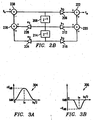
- FIGS. 5A and 5B graphically depict the functions of frequency shelf filters.
- Frequency shelf filters have a frequency response of unity at either 0 or fs /2, where fs is the frequency sample rate.
- a low-frequency shelf filter has a frequency response of unity at fs /2 and increases (or decreases) monotonically toward 0.
- a high-frequency shelf filter has a frequency response of unity at 0 and increases (or decreases) monotonically toward fs /2.
- Frequency shelf filters are used in digital tone processing of audio signals.
- Figure 5A represents the frequency response of a low-frequency shelf filter.
- Figure 5B represents the frequency response of a high-frequency shelf filter.
- the boost and cut responses represented in each figure are chosen to be symmetric.
- Figures 5A and 5B reflect that both low and high frequency shelf filters are tied to a frequency response of unity at one end, 0 or fs /2. Therefore, frequency shelf filters can be implemented as digital first-order or higher order IIR filters.
- the coefficients of a particular filter are calculated using one of several theoretical design procedures: Butterworth, Chebyshev, elliptic, etc. The design procedure produces values for the needed coefficients based on parameters for the filter such as frequency response.
- FIG. 3 graphically depicts the functions of an equalizer.
- An equalizer is a digital second-order IIR filter structure that allows boosting (gain larger than unity as in curve 304) or cutting (gain smaller than unity as in curve 306) of input signal frequencies centered around some design frequency f 0 ⁇ (0, fs /2). The gain is unity at the endpoints 0 and fs /2.
- Equalizers such as this are routinely used in audio tone control and speaker and room equalization in products such as consumer/PC audio, video, DVD and home theaters.
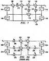
- FIGS 2A and 2B schematically show the direct form I (DFI-type) and direct form II (DFII-type) implementation architectures for a second order IIR digital filter.
- a DFI-type implementation is the network realization corresponding to a difference equation which describes a particular filter.
- a DFII-type, or canonical, implementation is a DFI-type implementation which uses the minimum number of delay elements required for realization of the difference equation. Note that in either implementation, a second order IIR digital filter includes 5 multiply elements or operations.
- Multiply operations tend to keep the DSP very busy due to the complexity of the mathematical operation.
- a reduction in multipliers decreases the number of clock cycles required for the filter to produce an output.
- multipliers are more complex than addition elements, the monetary cost of the implementation is reduced.
- the physical size of the DSP on which the digital filter is implemented can be reduced due to fewer components being needed to produce the same result.
- a DSP could implement more digital filters with the same number of multipliers with only slight variation to the architecture, including an increase in the number of addition elements.
- the present application discloses that digital equalizer filters can be implemented with fewer multipliers.
- the present disclosure uses at least one fewer multiplier for first and second order filters than current solutions.
- the present application discloses a 2-multiplier approach to first-order digital frequency shelf filters. Further, the present application discloses a 3 multiplier approach to second-order digital equalization filters.
- this new filter structure uses at least one fewer multiplier than present digital equalizer structures.
- This multiplier reduction enhances the capacity of the current audio equalizer DSP by 30 percent.
- the disclosed reduction in the number of multipliers required to implement some digital IIR equalization filter provides several advantages.
- One advantage is that the processing capacity of the audio equalizer DSP is enhanced by reducing the computational requirements imposed by first and second order digital IIR filters. That is, the number of multiply operations for first-order structures is reduced by 33 percent and the number of multiply operations for second-order structures is reduced by 25 percent.
- this multiplier-efficient structure would, as an example, enhance an 11-filter capacity DSP to at least a 14-filter capacity. This allows having the ability to provide enhanced and differentiated processing features for the same cost.
- the DSP can provide a 7-band stereo equalizer for substantially the same cost.
- Another practical advantage is that the present disclosure requires approximately 20 percent less computation in a microcode implementation of a DSP or one less multiplier in a dedicated hardware DSP and requires one fewer coefficient storage word in either case. This results in faster computational output and reduced cost.
- Figure 2A schematically shows the DFI-type implementation architecture for a second order IIR digital filter difference equation above. In DFI-type, separate delays are used for the input and output signals and separate addition elements are used for each term.
- Figure 2B schematically shows the DFII-type implementation architecture for a second order IIR digital filter.
- an input signal, x n is multiplied by the coefficient b 0 at multiplier 206.
- an input signal that has been delayed one time unit, x n-1 , by unit delay 208 is multiplied by the coefficient b 1 at multiplier 212.
- an input signal that has been delayed two time units, x n-2 , by unit delays 208 and 214 is multiplied by the coefficient b 2 at multiplier 218.
- the product of multiplier 212 is then added to the product of multiplier 218 at addition element 220.
- the result from addition element 220 is then added to the product of multiplier 206 at addition element 222.
- an output signal that has been delayed by one time unit, y n-1 , by unit delay 224 is multiplied by the coefficient a 1 226 at multiplier 228.
- an input signal that has been delayed by two time units, y n-2 , by unit delays 224 and 230 is multiplied by the coefficient a 2 at multiplier 234.
- the product of multiplier 234 is added to the product of multiplier 228 at addition element 236.
- the result from addition element 236 is subtracted from the result of addition element 222 at addition element 238.
- the result is output signal y n .
- the result of addition element 220 is then added to the product of multiplier 206 at addition element 222.
- an output signal that has been delayed by one time unit, y n-1 , by unit delay 204 is multiplied by the coefficient a 1 at multiplier 228.
- an input signal that has been delayed by two time unit, y n-2 , by unit delays 204 and 214 is multiplied by the coefficient a 2 at multiplier 234.
- the product of multiplier 234 is added to the product of multiplier 228 at addition element 236.
- the result from addition element 236 is subtracted from the result of addition element 222 at addition element 238.
- the result is output signal y n .
- Unit delays 208, 214, 224, and 230 provide a way for past values of input, output, and intermediate values within the filter to be made available.
- the time length of a unit delay is the time required to add one sample. For a k -bit sample added with a bit-serial adder, a one-unit delay represents k clock cycles. For samples added with a bit-parallel adder, a one-unit delay represents one clock cycle.
- Figures 6A and 6B show the innovative first-order digital IIR low-frequency and high-frequency shelf filters, respectively, with one fewer multiplier.
- Current DFI-type and DFII-type implementations of first-order digital IIR filters require 3 multipliers.
- This innovative filter requires two extra addition elements when compared to other first-order filter implementations.
- addition for multiplication trade off is desirable as an addition element is much cheaper, both in terms of monetary cost and system resources, to implement (in microcode or dedicated hardware) than a multiplier.
- Figure 1 shows a sample implementation of the innovative 3-multiplier second-order bi-quad equalizer digital IIR filter.
- Figure 1 like figures 2A and 2B, is a second-order digital IIR filter.
- fewer multipliers are used to implement the digital filter of Figure 1 when compared to Figures 2A and 2B. That is, 3 multipliers are used instead of 5.
- This innovative filter requires two extra addition elements when compared to the filter implementation of Figures 2A and 2B.
- addition for multiplication trade off is desirable as an addition element is much cheaper, both in terms of monetary cost and system resources, to implement (in microcode or dedicated hardware) than a multiplier.
- the digital IIR filter structure for first-order filters generally requires three multipliers. However, when constrained to operate as a shelf filter, the complexity of the implementation can be reduced to require only two multipliers.
- Figures 5A and 5B graphically depict first-order shelf response (boost or cut) for low-frequency and high-frequency shelf filters.
- H LF (z) the transfer function is represented by: H LF z
- H HF (z) the transfer function is represented by: H HF z
- FIGS. 6A and 6B schematically depict signal flow diagrams for the above time-domain representations of the low and high frequency shelf filters, respectively.
- FIG. 6A the implementation of the difference equation for a first-order low-frequency shelf filter is shown in signal flow diagram form.
- the input signal x n is added, at addition element 604 to an input signal that has been delayed one time unit, x n-1 , by unit delay 606 and multiplied by the coefficient b 1 at multiplier 610.
- the product is then added to the input signal, x n , at addition element 612.
- the input signal, x n is added to an output signal that has been delayed one time unit, y n-1 , by unit delay 614 at addition element 616.
- the result is multiplied by coefficient a 1 at multiplier 620.
- the product is subtracted from the result of addition element 612 at addition element 622.
- the result is output signal y n .
- FIG. 6B the implementation of the difference equation for a first-order high-frequency shelf filter is shown in signal flow diagram form.
- the input signal, x n is subtracted, at addition element 604 from an input signal that has been delayed one time unit, x n-1 , by unit delay 606 and multiplied by the coefficient b 1 at multiplier 610.
- the product is then added to the input signal, x n , at addition element 612.
- an output signal that has been delayed one time unit, y n-1 , by unit delay 614 is subtracted from the input signal, x n , at addition element 616.
- the result is multiplied by coefficient a 1 at multiplier 620.
- the product is added to the result of addition element 612 at addition element 622.
- the result is output signal y n .
- FIG. 7A the implementation of the alternative difference equation for a low-frequency shelf filter is shown in signal flow diagram form.
- the input signal, x n is added, at addition element 604 to an input signal that has been delayed one time unit, x n-1 , by unit delay 606 and multiplied by the coefficient b 0 626 at multiplier 610.
- the one time unit delayed input signal, x n-1 is then subtracted from the product of multiplier 610 at addition element 612.
- the one time unit delayed input signal, x n-1 is subtracted from an output signal that has been delayed one time unit, y n-1 , by unit delay 614 at addition element 616.
- the result is multiplied by coefficient a 1 at multiplier 620.
- the product is subtracted from the result of addition element 612 at addition element 622.
- the result is output signal y n .
- FIG. 7B the implementation of the alternative difference equation for a high-frequency shelf filter is shown in signal flow diagram form.
- An input signal that has been delayed one time unit by unit delay 606 is subtracted from the input signal, x n , at addition element 604 to and multiplied by the coefficient b 0 at multiplier 610.
- the one time unit delayed input signal, x n-1 is then added to the product of multiplier 610 at addition element 612.
- the one time unit delayed input signal, x n-1 is subtracted from an output signal that has been delayed one time unit, y n-1 , by unit delay 614 at addition element 616.
- the result is multiplied by coefficient a 1 at multiplier 620.
- the product is subtracted from the result of addition element 612 at addition element 622.
- the result is output signal y n .
- H LF (z) the transfer function is represented by: H z
- H HF H HF (z)
- Both the disclosed first and second order frequency shelf filters are implemented with fewer multipliers than current filter implementations.
- the disclosed implementations eliminate a multiplier and coefficient storage unit in favor of a greater number of addition operations while producing the same output. Any reduction in multiply operations, even at the expense of a greater number of addition elements is highly desirable. The benefit is substantial when multiple such filter structures are to be implemented in one DSP.
- Figure 1 schematically shows a DFI-type signal flow diagram which illustrates the implementation of the above difference equation using three coefficients, b 0 , a 1 , and a 2 .
- an input signal that has been delayed two time units, x n-2 , by unit delays 104 and 106 is subtracted from the input signal x n at addition element 108 and the result is multiplied by the coefficient b 0 at multiplier 112.
- the two time unit delayed input signal, x n-2 is then added to the product of multiplier 112 at addition element 114.
- an output signal that has been delayed by one time unit, y n-1 , by unit delay 116 is subtracted from an input signal that has been delayed by one time unit, x n-1 , by unit delay 104 at addition element 118 and the result is multiplied by coefficient a 1 at multiplier 122.
- the product of multiplier 120 is added to the result from addition element 114 at addition element 124.
- an output signal that has been delayed two time units, y n-2 , by unit delays 116 and 126 is subtracted from the two time unit delayed input signal, x n-2 , at addition element 128 and the result is multiplied by the coefficient a 2 at multiplier 132.
- the product of multiplier 130 is added to the result of addition element 134.
- the result is output signal y n .
- the disclosed second-order bi-quad equalizer digital IIR filter is implemented with fewer multipliers than current filter implementations of the same type and order.
- the disclosed implementations do require a greater number of addition operations to account for the reduced multipliers and coefficient storage demands.
- a multiplier implemented in add-shift architecture would require 12 addition operations. Replacement of such a multiplier by an addition element would save 11 addition operations. Therefore, any reduction in multiply operation, even at the expense of a greater number of addition elements is highly desirable. The benefit is substantial when multiple such filter structures are to be implemented in one DSP.
- Figure 4 schematically depicts the DFI-type signal flow diagram of the 3 multiplier second-order digital IIR equalizer filter of Figure 1, with a quantization step.
- the signal flow of Figure 1 is altered slightly to take account of the quantization steps.
- an input signal that has been delayed two time units, x n-2 , by unit delays 104 and 106 is subtracted from the input signal x n at addition element 108 and the result is multiplied by the coefficient b 0 at multiplier 112.
- the result is then quantized at quantizer 136.
- the two time unit delayed input signal, x n-2 is then added to the product of multiplier 112 at addition element 114.
- an output signal that has been delayed by one time unit, y n-1 , by unit delay 116 is subtracted from an input signal that has been delayed by one time unit, x n-1 , by unit delay 104 at addition element 118 and the result is multiplied by coefficient a 1 at multiplier 122.
- an output signal that has been delayed two time units, y n-2 , by unit delays 116 and 126 is subtracted from the two time unit delayed input signal, x n-2 , at addition element 128 and the result is multiplied by the coefficient a2 at multiplier 132.
- the product of multiplier 130 is added to the result of the product of multiplier 120 at addition element 124.
- the result is then quantized at quantizer 138.
- the result is then added to the result of addition element 114 at addition element 134.
- the result is output signal y n .
- Figure 9 depicts a block diagram of the signal processing of an audio system which utilizes the reduced multiplier digital IIR equalizer filters.
- An equalizer, audio tone control, and volume control are each part of a digital signal processing hardware which also includes a DSP controller, control circuitry and memory.
- the equalizer receives a digitized audio signal. The signal is processed by the DSP hardware.
- a digital to analog converter converts the signal for output as an analog audio signal which is received by a power amp and passed to the speaker system.
- the equalizer block utilizes 3-multiplier second-order digital IIR filters.
- the audio tone control block utilizes 2-multiplier frequency shelf filters.
- H(z) the transfer function, H(z), of a third-order filter
- Figure 10 schematically shows a DFI-type signal flow diagram which illustrates the implementation of the above difference equation using five coefficients, b 0 , b 1 , a 1 , a 2 , and a 3 .
- b 0 , b 1 , a 1 , a 2 , and a 3 Other equivalent representations of this third-order filter as well as filters of higher order are possible.
- a digital filter architecture implementing a desired transfer function which has at least one constrained endpoint value with a reduced number of multipliers, comprising: one or more chains of delay stages; a plurality of multiplier stages, consisting of less than 2j+1 multiplier stages in all; and a plurality of addition stages, interconnected with said multiplier stages and said delay stages which are no more than j samples deep, to implement a transfer function with one or more constrained endpoint values; wherein said multiplier stages implement a reduced coefficient set, which is reduced from 2j+1 by using a priori knowledge of said constrained endpoint value of said transfer function.
- a digital filter architecture implementing a desired transfer function which has at least two constrained endpoint values with a reduced number of multipliers, comprising: one or more chains of delay stages; a plurality of multiplier stages, consisting of exactly 2j-1 multiplier stages in all; and a plurality of addition stages, interconnected with said multiplier stages and said delay stages which are no more than j samples deep, to implement a transfer function with one or more constrained endpoint values; wherein said multiplier stages implement a set of only 2j-1 coefficients, which is reduced from 2j+1 by using a priori knowledge of said constrained endpoint values of said transfer function.
- a digital IIR filter with one fewer multiplier comprising: first and second delay chains each comprising at least two delay stages; a first addition stage connected to receive and combine the output of the intermediate node of said second delay chain and the output of the intermediate node of said first delay chain; a second addition stage connected to receive and combine the doubly delayed output of said second delay chain and the doubly delayed output of said first delay chain; a third addition stage connected to receive and combine the doubly delayed output of said first delay chain from an input signal; and a plurality of further arithmetic stages functionally connected to combine the output of said first addition stage multiplied by a first gain coefficient, the output of said second addition stage multiplied by a second gain coefficient, the output of said third addition stage multiplied by a third gain coefficient, and the doubly delayed output of said first delay chain; wherein said input signal is connected to an input of said first chain of delays and the output of said further stages is connected to an input of said second delay chain and also connected to
- a digital IIR filter with one fewer multiplier comprising: first and second delay chains each comprising at least one delay stage; a first addition stage connected to receive and combine the output of said second delay chain with an input signal; a second addition stage connected to receive and combine the output of said first delay chain and said input signal; and a plurality of further arithmetic stages functionally connected to combine the output of said first addition stage multiplied by a first gain coefficient, the output of said second addition stage multiplied by a second gain coefficient, and said input signal; wherein said input signal is connected to an input of said first chain of delays and the output of said further stages is connected to an input of said second delay chain and also connected to provide an output signal.
- a digital IIR filter with one fewer multiplier comprising: first and second delay chains each comprising at least one delay stage; a first addition stage connected to receive and combine the output of said first delay chain and said second delay chain; a second addition stage connected to receive and combine an input signal and the output of said first delay chain; and a plurality of further arithmetic stages functionally connected to combine the output of said first addition stage multiplied by a first gain coefficient, the output of said first delay chain, and the output of said second addition stage multiplied by a second gain coefficient; wherein said input signal is connected to an input of said first chain of delays and the output of said further stages is connected to an input of said second delay chain and also connected to provide an output signal.
- a programmable system comprising: at least one programmable processor and numeric hardware which is programmed to perform: one or more delay chain operations; a plurality of multiply operations, consisting of less than 2j+1 multiply operations in all; and a plurality of additions, interconnected with said multiply operations and with delay chain operations which are no more than j samples deep, to implement a transfer function with one or more constrained endpoint values; wherein said multiply operations implement a coefficient set, which is reduced from 2j+1 by using a priori knowledge of said constrained endpoint value of said transfer function.
- an audio system comprising: an audio source; a primp; a digital equalizer comprising: one or more chains of delay stages; a plurality of multiplier stages, consisting of less than 2j+1 multiplier stages in all; and a plurality of addition stages, interconnected with said multiplier stages and with delay stages which are no more than j samples deep, to implement a transfer function with one or more constrained endpoint values; wherein said multiplier stages implement a reduced coefficient set, which is reduced from 2j+1 by using a priori knowledge of said constrained endpoint value of said transfer function; a power amp; and speakers.
- a method of digital IIR filtering with a reduced number of multiplies, implementing a desired transfer function of order j which has at least one endpoint value constraint comprising the steps of: delaying digital signals for no more than j samples; and performing a plurality of addition operations and less than 2j+1 multiply operations, which in combination with said delaying step implement said transfer function with a coefficient set which is reduced from 2j+1 by using a priori knowledge of said endpoint constraint.
- the reduced multiplier filter although primarily for audio/video applications, can be utilized in any application with the constraint that the frequency response be unity at fs /2, 0, or both. This corresponds to a z-domain unity at 1, -1, or both. With a frequency response of unity at either fs /2 or 0, the reduction of one multiplier is achieved. With a frequency response of unity at both fs /2 and 0, the reduction of two multipliers is achieved.
- the reduced multiplier filter is not limited to just first and second-order filters. Filters of higher-order can make use of the reduced multiplier filter as long as the above constraints are met.
- DFI-type and DFII-type structures are derived from difference equations.
- the reduction in multipliers is not limited to DFI-type or DFII-type structures. Structures which are developed directly from a system function may also take advantage of the reduction in multipliers.
- other approaches such as those based on state-variable representations and linear transformations or on digital emulation of analog filters may also take advantage of the reduction in multipliers.
Landscapes
- Engineering & Computer Science (AREA)
- Physics & Mathematics (AREA)
- Computer Hardware Design (AREA)
- Mathematical Physics (AREA)
- Computing Systems (AREA)
- Theoretical Computer Science (AREA)
- Cable Transmission Systems, Equalization Of Radio And Reduction Of Echo (AREA)
- Complex Calculations (AREA)
- Networks Using Active Elements (AREA)
Applications Claiming Priority (2)
| Application Number | Priority Date | Filing Date | Title |
|---|---|---|---|
| US7158798P | 1998-01-15 | 1998-01-15 | |
| US71587 | 1998-01-15 |
Publications (2)
| Publication Number | Publication Date |
|---|---|
| EP0935342A2 true EP0935342A2 (fr) | 1999-08-11 |
| EP0935342A3 EP0935342A3 (fr) | 2001-05-16 |
Family
ID=22102285
Family Applications (1)
| Application Number | Title | Priority Date | Filing Date |
|---|---|---|---|
| EP19990300265 Ceased EP0935342A3 (fr) | 1998-01-15 | 1999-01-14 | Améliorations relatives aux filtres |
Country Status (3)
| Country | Link |
|---|---|
| US (1) | US6263354B1 (fr) |
| EP (1) | EP0935342A3 (fr) |
| JP (1) | JPH11261376A (fr) |
Cited By (2)
| Publication number | Priority date | Publication date | Assignee | Title |
|---|---|---|---|---|
| WO2022006100A1 (fr) * | 2020-06-30 | 2022-01-06 | Google Llc | Systèmes et procédés biquadratiques à faible puissance |
| EP4050473A1 (fr) * | 2021-02-25 | 2022-08-31 | Renesas Electronics Corporation | Dispositif semi-conducteur et dispositif de commande de moteur |
Families Citing this family (57)
| Publication number | Priority date | Publication date | Assignee | Title |
|---|---|---|---|---|
| US7035328B2 (en) * | 1999-02-08 | 2006-04-25 | Sunil Shukla | Method of slewing a digital filter providing filter sections with matched gain |
| US6711599B2 (en) * | 1999-12-03 | 2004-03-23 | Texas Instruments Incorporated | Limit-cycle-absent allpass filter lattice structure |
| JP2001211102A (ja) * | 2000-01-27 | 2001-08-03 | Nec Ic Microcomput Syst Ltd | レイク受信機 |
| US6845135B2 (en) * | 2001-01-22 | 2005-01-18 | Agere Systems Inc. | Cascaded biquad infinite impulse response filter |
| US7190712B2 (en) * | 2001-05-18 | 2007-03-13 | Global Locate, Inc | Method and apparatus for performing signal correlation |
| US20030014137A1 (en) * | 2001-07-16 | 2003-01-16 | Stephanus Saputro | Method and system for selecting a set of filter coefficients in a build-to-order computer system |
| KR100630112B1 (ko) * | 2002-07-09 | 2006-09-27 | 삼성전자주식회사 | 이동통신시스템의 적응형 채널 추정장치 및 방법 |
| US7152084B2 (en) * | 2002-11-08 | 2006-12-19 | Socovar, S.E.C. | Parallelized infinite impulse response (IIR) and integrator filters |
| US7290022B2 (en) * | 2003-11-17 | 2007-10-30 | Infineon Technologies Ag | Method and filter arrangement for digital recursive filtering in the time domain |
| US20050188183A1 (en) * | 2004-02-25 | 2005-08-25 | Analog Devices, Inc. | Digital signal processor having data address generator with speculative register file |
| US7698354B2 (en) * | 2004-04-16 | 2010-04-13 | Analog Devices, Inc. | Programmable engine core for executing digital signal processing functions |
| US7415542B2 (en) * | 2004-06-18 | 2008-08-19 | Analog Devices, Inc. | Micro-programmable filter engine having plurality of filter elements interconnected in chain configuration wherein engine supports multiple filters from filter elements |
| US7548941B2 (en) * | 2004-06-18 | 2009-06-16 | Analog Devices, Inc. | Digital filter using memory to emulate variable shift register |
| US7418467B2 (en) * | 2004-06-18 | 2008-08-26 | Analog Devices, Inc. | Micro-programmable digital filter |
| US10158337B2 (en) | 2004-08-10 | 2018-12-18 | Bongiovi Acoustics Llc | System and method for digital signal processing |
| US8462963B2 (en) * | 2004-08-10 | 2013-06-11 | Bongiovi Acoustics, LLCC | System and method for processing audio signal |
| US8284955B2 (en) | 2006-02-07 | 2012-10-09 | Bongiovi Acoustics Llc | System and method for digital signal processing |
| US8160274B2 (en) | 2006-02-07 | 2012-04-17 | Bongiovi Acoustics Llc. | System and method for digital signal processing |
| US10848118B2 (en) | 2004-08-10 | 2020-11-24 | Bongiovi Acoustics Llc | System and method for digital signal processing |
| US8565449B2 (en) * | 2006-02-07 | 2013-10-22 | Bongiovi Acoustics Llc. | System and method for digital signal processing |
| US11431312B2 (en) | 2004-08-10 | 2022-08-30 | Bongiovi Acoustics Llc | System and method for digital signal processing |
| US7254243B2 (en) * | 2004-08-10 | 2007-08-07 | Anthony Bongiovi | Processing of an audio signal for presentation in a high noise environment |
| US9281794B1 (en) | 2004-08-10 | 2016-03-08 | Bongiovi Acoustics Llc. | System and method for digital signal processing |
| US9413321B2 (en) | 2004-08-10 | 2016-08-09 | Bongiovi Acoustics Llc | System and method for digital signal processing |
| US7903772B2 (en) * | 2005-02-04 | 2011-03-08 | Broadcom Corporation | Digital demodulator with improved hardware and power efficiency |
| US7603400B2 (en) * | 2005-07-22 | 2009-10-13 | Broadcom Corporation | Method and system for filter loop with saturation |
| US10701505B2 (en) | 2006-02-07 | 2020-06-30 | Bongiovi Acoustics Llc. | System, method, and apparatus for generating and digitally processing a head related audio transfer function |
| US20090296959A1 (en) * | 2006-02-07 | 2009-12-03 | Bongiovi Acoustics, Llc | Mismatched speaker systems and methods |
| US9195433B2 (en) | 2006-02-07 | 2015-11-24 | Bongiovi Acoustics Llc | In-line signal processor |
| US9348904B2 (en) | 2006-02-07 | 2016-05-24 | Bongiovi Acoustics Llc. | System and method for digital signal processing |
| US10848867B2 (en) | 2006-02-07 | 2020-11-24 | Bongiovi Acoustics Llc | System and method for digital signal processing |
| US11202161B2 (en) | 2006-02-07 | 2021-12-14 | Bongiovi Acoustics Llc | System, method, and apparatus for generating and digitally processing a head related audio transfer function |
| US10069471B2 (en) | 2006-02-07 | 2018-09-04 | Bongiovi Acoustics Llc | System and method for digital signal processing |
| US9615189B2 (en) | 2014-08-08 | 2017-04-04 | Bongiovi Acoustics Llc | Artificial ear apparatus and associated methods for generating a head related audio transfer function |
| US8705765B2 (en) * | 2006-02-07 | 2014-04-22 | Bongiovi Acoustics Llc. | Ringtone enhancement systems and methods |
| US7788308B2 (en) * | 2006-03-20 | 2010-08-31 | Rane Corporation | Frequency float method and system for realizing a signal filter |
| KR100790163B1 (ko) * | 2006-08-08 | 2008-01-02 | 삼성전자주식회사 | 이동통신 단말기의 이동속도에 따라 iir 필터 계수를 변경하는 채널 추정장치 및 계수 변경 방법 |
| NZ577201A (en) * | 2006-11-30 | 2012-06-29 | Anthony Bongiovi | Signal filtering and compression method for high-quality sound emulation |
| US8509457B2 (en) * | 2006-12-11 | 2013-08-13 | Thx, Ltd. | Tone balance volume control |
| US8452028B2 (en) * | 2006-12-12 | 2013-05-28 | Thx, Ltd. | Dynamic surround channel volume control |
| US9344828B2 (en) | 2012-12-21 | 2016-05-17 | Bongiovi Acoustics Llc. | System and method for digital signal processing |
| US9178545B2 (en) | 2013-04-11 | 2015-11-03 | Stmicroelectronics Asia Pacific Pte Ltd | Digital IIR filter with adjustable filter weights based on measured changes in the processed data |
| US9883318B2 (en) | 2013-06-12 | 2018-01-30 | Bongiovi Acoustics Llc | System and method for stereo field enhancement in two-channel audio systems |
| US9264004B2 (en) | 2013-06-12 | 2016-02-16 | Bongiovi Acoustics Llc | System and method for narrow bandwidth digital signal processing |
| US9398394B2 (en) | 2013-06-12 | 2016-07-19 | Bongiovi Acoustics Llc | System and method for stereo field enhancement in two-channel audio systems |
| US9906858B2 (en) | 2013-10-22 | 2018-02-27 | Bongiovi Acoustics Llc | System and method for digital signal processing |
| US9397629B2 (en) | 2013-10-22 | 2016-07-19 | Bongiovi Acoustics Llc | System and method for digital signal processing |
| US10820883B2 (en) | 2014-04-16 | 2020-11-03 | Bongiovi Acoustics Llc | Noise reduction assembly for auscultation of a body |
| US10639000B2 (en) | 2014-04-16 | 2020-05-05 | Bongiovi Acoustics Llc | Device for wide-band auscultation |
| US9615813B2 (en) | 2014-04-16 | 2017-04-11 | Bongiovi Acoustics Llc. | Device for wide-band auscultation |
| US9564146B2 (en) | 2014-08-01 | 2017-02-07 | Bongiovi Acoustics Llc | System and method for digital signal processing in deep diving environment |
| US9638672B2 (en) | 2015-03-06 | 2017-05-02 | Bongiovi Acoustics Llc | System and method for acquiring acoustic information from a resonating body |
| US9621994B1 (en) | 2015-11-16 | 2017-04-11 | Bongiovi Acoustics Llc | Surface acoustic transducer |
| JP2018537910A (ja) | 2015-11-16 | 2018-12-20 | ボンジョビ アコースティックス リミテッド ライアビリティー カンパニー | 表面音響変換器 |
| JP2021521700A (ja) | 2018-04-11 | 2021-08-26 | ボンジョビ アコースティックス リミテッド ライアビリティー カンパニー | オーディオ強化聴力保護システム |
| WO2020028833A1 (fr) | 2018-08-02 | 2020-02-06 | Bongiovi Acoustics Llc | Système, procédé et appareil pour générer et traiter numériquement une fonction de transfert audio liée à la tête |
| JP2025020474A (ja) * | 2021-12-28 | 2025-02-13 | アルプスアルパイン株式会社 | フィルタ設計方法、及び、iir型全域通過フィルタ |
Citations (1)
| Publication number | Priority date | Publication date | Assignee | Title |
|---|---|---|---|---|
| GB2081047A (en) * | 1980-06-30 | 1982-02-10 | Hewlett Packard Co | Recursive low pass digital filter |
Family Cites Families (6)
| Publication number | Priority date | Publication date | Assignee | Title |
|---|---|---|---|---|
| US4630299A (en) * | 1985-02-22 | 1986-12-16 | General Electric Company | Digital circuit for decoding digitized, demodulated FM stereo signals |
| US4783756A (en) * | 1986-09-24 | 1988-11-08 | Rca Licensing Corporation | Sampled data tone control system |
| JPH0828649B2 (ja) * | 1989-02-16 | 1996-03-21 | 日本電気株式会社 | ディジタルフィルタ |
| US5170369A (en) * | 1989-09-25 | 1992-12-08 | E-Mu Systems, Inc. | Dynamic digital IIR audio filter and method which provides dynamic digital filtering for audio signals |
| US5339264A (en) * | 1992-07-27 | 1994-08-16 | Tektronix, Inc. | Symmetric transposed FIR digital filter |
| US6009445A (en) * | 1997-10-15 | 1999-12-28 | Zilog, Inc. | Reconfigurable infinite impulse response digital filter |
-
1999
- 1999-01-14 EP EP19990300265 patent/EP0935342A3/fr not_active Ceased
- 1999-01-15 US US09/232,430 patent/US6263354B1/en not_active Expired - Lifetime
- 1999-01-18 JP JP11009883A patent/JPH11261376A/ja active Pending
Patent Citations (1)
| Publication number | Priority date | Publication date | Assignee | Title |
|---|---|---|---|---|
| GB2081047A (en) * | 1980-06-30 | 1982-02-10 | Hewlett Packard Co | Recursive low pass digital filter |
Cited By (4)
| Publication number | Priority date | Publication date | Assignee | Title |
|---|---|---|---|---|
| WO2022006100A1 (fr) * | 2020-06-30 | 2022-01-06 | Google Llc | Systèmes et procédés biquadratiques à faible puissance |
| US11652471B2 (en) | 2020-06-30 | 2023-05-16 | Google Llc | Low power biquad systems and methods |
| EP4050473A1 (fr) * | 2021-02-25 | 2022-08-31 | Renesas Electronics Corporation | Dispositif semi-conducteur et dispositif de commande de moteur |
| US11949358B2 (en) | 2021-02-25 | 2024-04-02 | Renesas Electronics Corporation | Semiconductor device and motor control device |
Also Published As
| Publication number | Publication date |
|---|---|
| EP0935342A3 (fr) | 2001-05-16 |
| US6263354B1 (en) | 2001-07-17 |
| JPH11261376A (ja) | 1999-09-24 |
Similar Documents
| Publication | Publication Date | Title |
|---|---|---|
| EP0935342A2 (fr) | Améliorations relatives aux filtres | |
| JPH07297680A (ja) | デジタルフィルタ及びデジタル信号のフィルタリング方法 | |
| JPH0629786A (ja) | デジタル・インターポレーション用低精度firフィルタ | |
| US7159002B2 (en) | Biquad digital filter operating at maximum efficiency | |
| WO2003069499A1 (fr) | Ensemble de filtres pour l'analyse de frequence | |
| US4920507A (en) | Recursive digital filter with less no-signal noise | |
| WO2008045713A2 (fr) | Procédés et systèmes de mise en oeuvre d'un convertisseur numérique-analogique | |
| JP3223188B2 (ja) | 積の数を減らすことによりディジタルフィルタバンクの電力消費を減らす方法 | |
| JPH08508374A (ja) | デシメーション・フィルター | |
| Lian | Complexity reduction for FRM-based FIR filters using the prefilter-equalizer technique | |
| Fam | MFIR filters: Properties and applications | |
| US7212874B2 (en) | Noise-shapers and filters with noise shaping quantizers and systems and methods using the same | |
| US20100077014A1 (en) | Second order real allpass filter | |
| US7492848B2 (en) | Method and apparatus for efficient multi-stage FIR filters | |
| Bhakthavatchalu et al. | Design of optimized CIC decimator and interpolator in FPGA | |
| Abinaya et al. | Heuristic Analysis of Multiplierless Desensitized Half-Band Decimation Filter for Wireless Applications | |
| GB2455806A (en) | Infinite impulse response filter | |
| US7292630B2 (en) | Limit-cycle-free FIR/IIR halfband digital filter with shared registers for high-speed sigma-delta A/D and D/A converters | |
| Anzova et al. | An algorithm for the design of multiplierless IIR filters as a parallel connection of two all-pass filters | |
| Mottaghi-Kashtiban et al. | FIR filters involving shifts and only two additions, efficient for short word-length signal processing | |
| JP5540211B2 (ja) | 1ビットオーディオ信号用イコライズ装置 | |
| Bruckmann | Design and realization of continuous-time wave digital filters | |
| Eraluoto et al. | VLSI implementation of high speed digital filters using direct form delta structures | |
| Sai Lakshmi Chaitanya et al. | FIR and folded IIR filter designs for speech processing in hearing AID | |
| Chukwuchekwa et al. | Enhancement of the performance characteristics of CIC decimation filters for multirate DSP applications |
Legal Events
| Date | Code | Title | Description |
|---|---|---|---|
| PUAI | Public reference made under article 153(3) epc to a published international application that has entered the european phase |
Free format text: ORIGINAL CODE: 0009012 |
|
| AK | Designated contracting states |
Kind code of ref document: A2 Designated state(s): DE FR GB IT NL |
|
| AX | Request for extension of the european patent |
Free format text: AL;LT;LV;MK;RO;SI |
|
| PUAL | Search report despatched |
Free format text: ORIGINAL CODE: 0009013 |
|
| AK | Designated contracting states |
Kind code of ref document: A3 Designated state(s): AT BE CH CY DE DK ES FI FR GB GR IE IT LI LU MC NL PT SE |
|
| AX | Request for extension of the european patent |
Free format text: AL;LT;LV;MK;RO;SI |
|
| 17P | Request for examination filed |
Effective date: 20011116 |
|
| AKX | Designation fees paid |
Free format text: DE FR GB IT NL |
|
| 17Q | First examination report despatched |
Effective date: 20080402 |
|
| APBK | Appeal reference recorded |
Free format text: ORIGINAL CODE: EPIDOSNREFNE |
|
| APBN | Date of receipt of notice of appeal recorded |
Free format text: ORIGINAL CODE: EPIDOSNNOA2E |
|
| APAF | Appeal reference modified |
Free format text: ORIGINAL CODE: EPIDOSCREFNE |
|
| APBT | Appeal procedure closed |
Free format text: ORIGINAL CODE: EPIDOSNNOA9E |
|
| STAA | Information on the status of an ep patent application or granted ep patent |
Free format text: STATUS: THE APPLICATION HAS BEEN REFUSED |
|
| 18R | Application refused |
Effective date: 20151110 |