EP0935580B1 - Aufzugsführungsschiene - Google Patents
Aufzugsführungsschiene Download PDFInfo
- Publication number
- EP0935580B1 EP0935580B1 EP97947317A EP97947317A EP0935580B1 EP 0935580 B1 EP0935580 B1 EP 0935580B1 EP 97947317 A EP97947317 A EP 97947317A EP 97947317 A EP97947317 A EP 97947317A EP 0935580 B1 EP0935580 B1 EP 0935580B1
- Authority
- EP
- European Patent Office
- Prior art keywords
- guide rail
- car
- counterweight
- central portion
- lateral portions
- Prior art date
- Legal status (The legal status is an assumption and is not a legal conclusion. Google has not performed a legal analysis and makes no representation as to the accuracy of the status listed.)
- Expired - Lifetime
Links
- 230000013011 mating Effects 0.000 claims description 3
- 239000000463 material Substances 0.000 description 4
- 238000009434 installation Methods 0.000 description 3
- 229910000831 Steel Inorganic materials 0.000 description 1
- 239000010959 steel Substances 0.000 description 1
Images


Classifications
-
- B—PERFORMING OPERATIONS; TRANSPORTING
- B66—HOISTING; LIFTING; HAULING
- B66B—ELEVATORS; ESCALATORS OR MOVING WALKWAYS
- B66B7/00—Other common features of elevators
- B66B7/02—Guideways; Guides
- B66B7/022—Guideways; Guides with a special shape
Definitions
- the present invention relates to elevators, and more particularly to guide rails for elevators.
- FIG. 7 A known type of elevator is illustrated in Figure 7.
- An elevator car 101 moves up and down in an elevator hoistway 102.
- a counterweight 103 balances the car 101.
- One end of a rope 104 is attached to the car, and the other end is attached to the counterweight.
- the rope 104 extends over a drive sheave 105a and a deflector sheave 106 of a hoist machine 105.
- car guide rails 107 and counterweight guide rails 108 are provided on both sides of the car 101 and the counterweight 103.
- the car and the counterweight move up and down respectively along the car guide rails and the counterweight guide rails.
- a drawback with this known type of elevator is the amount of installation work caused by the car guide rails 107 and the counterweight guide rails 108 having to be installed and aligned separately.
- US-A-3211259 discloses a guide rail for an elevator car and counterweight, the guide rail having two guiding surfaces, one for the car and the other for the counterweight.
- an elevator system including an elevator car, a counterweight, and a guide rail for both the car and the counterweight, the guide rail having two guiding surfaces, one for the car and the other for the counterweight, the guide rail comprising a central portion having a base and two flanges extending outward from the base, and a pair of lateral portions, each lateral portion having a first side and a second side, each first side mating with and being fastened to a respective one of the two said flanges to define a respective one of the two guiding surfaces therewith.
- the combined car and counterweight guide rail comprises a central portion having a U-shaped cross section and a pair of lateral portions having L-shaped cross sections, the lateral portions being arranged on the respective sides of the central portion.
- the two flanges of the central portion are bent back to form shaped edge sections, and the lateral portions are received within such edge sections.
- An advantage of the present invention is the ease of installation of the guide rails. Since guide rails for both the car and the counterweight are integrated into a single structure, they are installed simultaneously. This eliminates the need to separately install car and counterweight guide rails and reduces the effort in aligning the guide rails. Another advantage is that readily available materials may be used to form the guide rails. Thus in one embodiment the rails are formed from sheet material shaped into the appropriate forms. Alternatively, conventional U-shaped channels and L-shaped bars may be used.
- a car 1 is installed in an elevator hoistway 2 in a manner such that it can freely move up and down.
- a cab door 3 is installed in a manner such that it can freely open and close.
- a door pocket 1b is provided to store the door 3 when it is opened.
- a car guide rail 4 and a counterweight guide rail 5 are vertically installed together. As a result of this the elevator hoistway 2 is made compact in the horizontal direction.
- the car 1 comprises a cab 6 and a frame 7 which supports the cab 6.
- the frame 7 comprises a lower frame 7a located under the floor of the cab 6, and a side frame 7b which is located on the side face of the cab on the door pocket side.
- the side frame 7b is positioned on the side face of the car 1 at a position slightly below the upper end 1c thereof, that is the ceiling.
- roller guides 8 and 9 are provided at the ends of both the lower frame 7a and the side frame 7b of the car frame 7. These roller guides 8 and 9 are engaged with the car guide rail 4 in freely slidable fashion.
- a counterweight 10 is provided to balance the car 1.
- guide shoes 11 and 12 are provided on both the upper and the lower ends of the counterweight 10.
- the guide shoes 11 and 12 are engaged with the counterweight guide rail 5 in freely slidable fashion.
- the rope 13 extends over a drive sheave 14a of a hoist machine 14 that is mounted on the upper part of the car guide rail 4 and counterweight guide rail 5 structure. As a result, the load of the car, the counterweight and the hoist machine is carried by the guide rail structure. When the car 1 is positioned on the top floor, the hoist machine 14 is positioned beside the car.
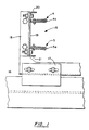
- the car guide rail 4 and the counterweight guide rail 5 are combined, as illustrated in Figure 1, to constitute an integral guide rail 15.
- the combined guide rail 15 defines the guiding surfaces for both the car 1 and the counterweight 10, and is fixed to the structure of the elevator hoistway 2 by means of a support piece 17 and a rail bracket 18.
- the combined guide rail 15 comprises a central portion 19 and a pair of lateral portions 20 and 21 made of sheet steel.
- the central portion includes a base and a pair of flanges extending outward from the base to form a generally U-shaped cross section.
- the lateral portions 20 and 21 each include a first side and a second side arranged to form a generally L-shaped cross section.
- the lateral portions 20 and 21 are arranged on the respective sides of the central portion 19, with one each of their sides mating with one of the flanges of the central portion.
- the left and right flanges of the central portion 19 are respectively shaped to form an edge section 4a of the car guide rail 4 and an edge section 5a of the counterweight guide rail 5.
- the shaped edge sections 4a and 5a define cavities in which the lateral portions 20 and 21 are respectively inserted and received.
- the guiding surfaces are defined by the central portion 19 and the shaped edge sections 4a and 5a.
- the lateral portions may be configured with the shaped edge sections and the flanges of the central portion received within the lateral portions. In this configuration, the guiding surfaces would be defined by the lateral portions.
- the left and right sides of the central portion 19 are extruded and pressed to have a U-shaped cross section that opens outwards to the left and right by means of the remaining stress.
- the pair of lateral portions 20 and 21 are extruded and pressed to have L-shaped cross sections that open inward from the left and right by means of the remaining stress.
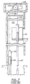
- the combined guide rail 15 is extended through the hoistway by connecting together a number of rail structures 22 and 23.
- the longitudinal ends of the central portion 19 and the lateral portions 20 and 21 are slightly displaced on the rail structures 22 and 23.
- the lateral portions 20 and 21 of one rail structure 23 can be inserted in the central portion 19 of the adjacent rail structure 22.
- the edge sections 4a and 5a of the rail structure 22 and the edge sections 4a and 5a of the rail structure 23 will mate.
- the central portion 19 of the rail structure 22 and the lateral portions 20 and 21 of the rail structure 23 are joined with bolts, and further joined with bolts by means of a splice plate 24.
- each guiding surface would be defined in part by a flange of the central portion and in part by one side of the lateral portion.
Landscapes
- Lift-Guide Devices, And Elevator Ropes And Cables (AREA)
- Cage And Drive Apparatuses For Elevators (AREA)
Claims (5)
- Aufzugsystem mit einem Aufzugfahrkorb (1), einem Gegengewicht (10) und einer Führungsschiene (15) sowohl für den Fahrkorb als auch für das Gegengewicht, wobei die Führungsschiene zwei Führungsflächen aufweist, und zwar die eine (4) für den Fahrkorb und die andere (5) für das Gegengewicht, wobei die Führungsschiene einen zentralen Bereich (19) mit einer Basis und zwei sich von der Basis nach außen erstreckenden Flanschen sowie ein Paar seitlicher Bereiche (20, 21) aufweist, wobei jeder seitliche Bereich eine erste Seite und eine zweite Seite aufweist, wobei jede erste Seite mit einem jeweiligen der beiden Flansche zusammenpasst und an diesem befestigt ist, um eine jeweilige der beiden Führungsflächen mit diesem zu bilden.
- Aufzugsystem nach Anspruch 1,
wobei der zentrale Bereich (19) der Führungsschiene aus einer Konstruktion mit U-förmigem Querschnitt gebildet. - Aufzugsystem nach Anspruch 1 oder 2,
wobei jeder der seitlichen Bereiche (20, 21) der Führungsschiene aus einer Konstruktion mit L-förmigem Querschnitt gebildet ist. - Aufzugsystem nach einem der Ansprüche 1 bis 3,
wobei bei jeder Führungsfläche der Führungsschiene entweder der genannte Flansch oder die genannte erste Seite einen geformten Randbereich (4a, 5a) aufweist, der einen Hohlraum bildet, der das jeweils andere dieser Teile aufnimmt. - Aufzugsystem nach Anspruch 4,
wobei der genannte Randbereich (4a, 5a) teilweise die Führungsfläche bildet.
Applications Claiming Priority (4)
| Application Number | Priority Date | Filing Date | Title |
|---|---|---|---|
| JP29007796A JP3910667B2 (ja) | 1996-10-31 | 1996-10-31 | エレベーターの合体型ガイドレール |
| JP29007796 | 1996-10-31 | ||
| US08/962,305 US6012554A (en) | 1996-10-31 | 1997-10-31 | Elevator guide rail |
| PCT/US1997/019905 WO1998018709A1 (en) | 1996-10-31 | 1997-10-31 | Elevator guide rail |
Publications (2)
| Publication Number | Publication Date |
|---|---|
| EP0935580A1 EP0935580A1 (de) | 1999-08-18 |
| EP0935580B1 true EP0935580B1 (de) | 2002-06-12 |
Family
ID=26557875
Family Applications (1)
| Application Number | Title | Priority Date | Filing Date |
|---|---|---|---|
| EP97947317A Expired - Lifetime EP0935580B1 (de) | 1996-10-31 | 1997-10-31 | Aufzugsführungsschiene |
Country Status (8)
| Country | Link |
|---|---|
| US (1) | US6012554A (de) |
| EP (1) | EP0935580B1 (de) |
| JP (1) | JP3910667B2 (de) |
| CN (1) | CN1082487C (de) |
| CA (1) | CA2270219A1 (de) |
| DE (1) | DE69713368T2 (de) |
| ES (1) | ES2175479T3 (de) |
| WO (1) | WO1998018709A1 (de) |
Cited By (1)
| Publication number | Priority date | Publication date | Assignee | Title |
|---|---|---|---|---|
| EP1328460A1 (de) | 2000-09-12 | 2003-07-23 | Kone Corporation | Stützstruktur für aufzugsführungsschienen |
Families Citing this family (18)
| Publication number | Priority date | Publication date | Assignee | Title |
|---|---|---|---|---|
| PL190277B1 (pl) | 1997-12-23 | 2005-11-30 | Inventio Ag | Winda linowa z kołem napędowym |
| US6431322B1 (en) * | 2000-07-31 | 2002-08-13 | Inventio Ag | Plunger guide for a telescopic jack in a hydraulic elevator |
| US6481538B2 (en) * | 2000-08-30 | 2002-11-19 | Otis Elevator Company | Elevator guide rail mounting assembly |
| US7234566B2 (en) * | 2003-09-15 | 2007-06-26 | The Vertical Solutions Company, Inc. | Elevator insert |
| DE102004026507A1 (de) * | 2004-05-27 | 2005-12-15 | Winkel Gmbh | Hubvorrichtung |
| EP1876132A1 (de) * | 2006-07-07 | 2008-01-09 | Inventio Ag | Führungsschiene für Aufzüge |
| EP1876133B1 (de) * | 2006-07-07 | 2011-10-19 | Inventio AG | Führungsschiene für einen Aufzug |
| RU2007132738A (ru) * | 2006-08-31 | 2009-03-10 | Инвенцио АГ (CH) | Подъемник с кабиной и противовесом и способ размещения подъемника |
| ES2509352T3 (es) * | 2008-05-16 | 2014-10-17 | Thyssenkrupp Elevator Ag | Elemento de barra longitudinal para una caja de una instalación de elevador |
| WO2015075498A1 (en) * | 2013-11-22 | 2015-05-28 | Otis Elevator Company | Elevator system with counterweight |
| WO2015118188A1 (es) * | 2014-02-04 | 2015-08-13 | Otis Elevator Company | Carril de guía combinado para un sistema de ascensor |
| CN103879857B (zh) * | 2014-03-13 | 2016-05-11 | 苏州市华威电梯部件有限公司 | 一种双r角电梯钢导轨 |
| CN104555657B (zh) * | 2015-01-26 | 2017-05-03 | 江门市蒙德电气股份有限公司 | 一种新型电梯导轨 |
| CN105668378A (zh) * | 2016-04-15 | 2016-06-15 | 苏州工业职业技术学院 | 一种电梯导轨结构及其电梯 |
| CN108328455B (zh) * | 2018-04-04 | 2019-08-16 | 浙江蒂尔森电梯有限公司 | 一种高速电梯导轨 |
| SG11202106078YA (en) * | 2018-12-20 | 2021-07-29 | Inventio Ag | Lift rail |
| EP4397615B1 (de) * | 2023-01-05 | 2025-06-25 | Inventio Ag | Aufzugsanlage |
| EP4424625A1 (de) * | 2023-03-03 | 2024-09-04 | Otis Elevator Company | Aufzugsführungsschiene |
Family Cites Families (5)
| Publication number | Priority date | Publication date | Assignee | Title |
|---|---|---|---|---|
| US3211259A (en) * | 1962-11-09 | 1965-10-12 | Otis Elevator Co | Monorail for counterweight frames |
| FR2242318A1 (en) * | 1973-09-03 | 1975-03-28 | Durand Francois | Lift using rolled steel beam as guide track - lift cabin and counterweights run along opposite sides of beam |
| JPS60223772A (ja) * | 1984-04-18 | 1985-11-08 | 三菱電機株式会社 | エレベ−タ用ガイドレ−ル |
| FI94123C (fi) * | 1993-06-28 | 1995-07-25 | Kone Oy | Vetopyörähissi |
| FI93632C (fi) * | 1993-06-28 | 1995-05-10 | Kone Oy | Alakoneistoinen vetopyörähissi |
-
1996
- 1996-10-31 JP JP29007796A patent/JP3910667B2/ja not_active Expired - Fee Related
-
1997
- 1997-10-31 ES ES97947317T patent/ES2175479T3/es not_active Expired - Lifetime
- 1997-10-31 WO PCT/US1997/019905 patent/WO1998018709A1/en not_active Ceased
- 1997-10-31 US US08/962,305 patent/US6012554A/en not_active Expired - Lifetime
- 1997-10-31 EP EP97947317A patent/EP0935580B1/de not_active Expired - Lifetime
- 1997-10-31 CN CN97199284.3A patent/CN1082487C/zh not_active Expired - Fee Related
- 1997-10-31 CA CA002270219A patent/CA2270219A1/en not_active Abandoned
- 1997-10-31 DE DE69713368T patent/DE69713368T2/de not_active Expired - Lifetime
Cited By (1)
| Publication number | Priority date | Publication date | Assignee | Title |
|---|---|---|---|---|
| EP1328460A1 (de) | 2000-09-12 | 2003-07-23 | Kone Corporation | Stützstruktur für aufzugsführungsschienen |
Also Published As
| Publication number | Publication date |
|---|---|
| US6012554A (en) | 2000-01-11 |
| WO1998018709A1 (en) | 1998-05-07 |
| EP0935580A1 (de) | 1999-08-18 |
| JP3910667B2 (ja) | 2007-04-25 |
| CN1235587A (zh) | 1999-11-17 |
| JPH10139307A (ja) | 1998-05-26 |
| ES2175479T3 (es) | 2002-11-16 |
| DE69713368T2 (de) | 2003-04-03 |
| CA2270219A1 (en) | 1998-05-07 |
| CN1082487C (zh) | 2002-04-10 |
| DE69713368D1 (de) | 2002-07-18 |
Similar Documents
| Publication | Publication Date | Title |
|---|---|---|
| EP0935580B1 (de) | Aufzugsführungsschiene | |
| US6234276B1 (en) | Traction type elevator having cable hitches securing cable ends to guide rails | |
| EP1018480B1 (de) | Seilführung und Antriebsstelle für Aufzug | |
| US6742628B2 (en) | Rope elevator | |
| US8302740B2 (en) | Integrated support for elevator machine, sheaves and terminations | |
| CA2429084C (en) | Elevator safety plank assembly | |
| EP1767485B1 (de) | Aufzug | |
| US20040173411A1 (en) | Elevator | |
| CN110844754B (zh) | 无框架电梯对重 | |
| EP0938445B1 (de) | Aufzugkabine | |
| US7481300B2 (en) | Elevator roping arrangement | |
| KR910000579B1 (ko) | 엘리베이터용 가이드 레일 | |
| EP0762987B1 (de) | Mehrzweckverbindungs- und stützelement einer vorrichtung für automatische türbewegung von liften und aufzügen | |
| JPH1087223A (ja) | エレベーターのガイドレール | |
| EP1328460B1 (de) | Stützstruktur für aufzugsführungsschienen | |
| EP3274285B1 (de) | Aufhängungselementabschluss eines aufzugssystems | |
| JP7369303B2 (ja) | 乗りかご及びエレベーター | |
| US20260048962A1 (en) | Elevator system having three combined guiding points for elevator car and counterweight | |
| EP4717655A1 (de) | Aufzugsanlage mit einer führungsstruktur, die mindestens eine führungsschienenhalterung umfasst | |
| WO2003066499A1 (en) | Compact elevator car | |
| JP2004123273A (ja) | エレベータの乗りかご | |
| JPH092757A (ja) | ユニット式建物におけるエレベータのガイドレール | |
| CA2191720C (en) | A multifunction connection and support element in a mechanism for automatic door motion for lifts and elevators | |
| JP2021178727A (ja) | エレベーター及び乗り場ドア | |
| CN110997545A (zh) | 电梯轿厢 |
Legal Events
| Date | Code | Title | Description |
|---|---|---|---|
| PUAI | Public reference made under article 153(3) epc to a published international application that has entered the european phase |
Free format text: ORIGINAL CODE: 0009012 |
|
| 17P | Request for examination filed |
Effective date: 19990525 |
|
| AK | Designated contracting states |
Kind code of ref document: A1 Designated state(s): DE ES FR IT |
|
| 17Q | First examination report despatched |
Effective date: 20001123 |
|
| GRAG | Despatch of communication of intention to grant |
Free format text: ORIGINAL CODE: EPIDOS AGRA |
|
| GRAG | Despatch of communication of intention to grant |
Free format text: ORIGINAL CODE: EPIDOS AGRA |
|
| GRAH | Despatch of communication of intention to grant a patent |
Free format text: ORIGINAL CODE: EPIDOS IGRA |
|
| GRAH | Despatch of communication of intention to grant a patent |
Free format text: ORIGINAL CODE: EPIDOS IGRA |
|
| GRAA | (expected) grant |
Free format text: ORIGINAL CODE: 0009210 |
|
| AK | Designated contracting states |
Kind code of ref document: B1 Designated state(s): DE ES FR IT |
|
| REF | Corresponds to: |
Ref document number: 69713368 Country of ref document: DE Date of ref document: 20020718 |
|
| ET | Fr: translation filed | ||
| REG | Reference to a national code |
Ref country code: ES Ref legal event code: FG2A Ref document number: 2175479 Country of ref document: ES Kind code of ref document: T3 |
|
| PLBE | No opposition filed within time limit |
Free format text: ORIGINAL CODE: 0009261 |
|
| STAA | Information on the status of an ep patent application or granted ep patent |
Free format text: STATUS: NO OPPOSITION FILED WITHIN TIME LIMIT |
|
| 26N | No opposition filed |
Effective date: 20030313 |
|
| PGFP | Annual fee paid to national office [announced via postgrant information from national office to epo] |
Ref country code: ES Payment date: 20130911 Year of fee payment: 17 |
|
| PGFP | Annual fee paid to national office [announced via postgrant information from national office to epo] |
Ref country code: FR Payment date: 20131009 Year of fee payment: 17 Ref country code: DE Payment date: 20131023 Year of fee payment: 17 |
|
| PGFP | Annual fee paid to national office [announced via postgrant information from national office to epo] |
Ref country code: IT Payment date: 20131023 Year of fee payment: 17 |
|
| REG | Reference to a national code |
Ref country code: DE Ref legal event code: R119 Ref document number: 69713368 Country of ref document: DE |
|
| PG25 | Lapsed in a contracting state [announced via postgrant information from national office to epo] |
Ref country code: DE Free format text: LAPSE BECAUSE OF NON-PAYMENT OF DUE FEES Effective date: 20150501 |
|
| REG | Reference to a national code |
Ref country code: FR Ref legal event code: ST Effective date: 20150630 |
|
| PG25 | Lapsed in a contracting state [announced via postgrant information from national office to epo] |
Ref country code: FR Free format text: LAPSE BECAUSE OF NON-PAYMENT OF DUE FEES Effective date: 20141031 Ref country code: IT Free format text: LAPSE BECAUSE OF NON-PAYMENT OF DUE FEES Effective date: 20141031 |
|
| REG | Reference to a national code |
Ref country code: ES Ref legal event code: FD2A Effective date: 20151127 |
|
| PG25 | Lapsed in a contracting state [announced via postgrant information from national office to epo] |
Ref country code: ES Free format text: LAPSE BECAUSE OF NON-PAYMENT OF DUE FEES Effective date: 20141101 |