EP0936165A2 - Pneumatische Roller und Papierhandhabungsanordnung - Google Patents
Pneumatische Roller und Papierhandhabungsanordnung Download PDFInfo
- Publication number
- EP0936165A2 EP0936165A2 EP99102011A EP99102011A EP0936165A2 EP 0936165 A2 EP0936165 A2 EP 0936165A2 EP 99102011 A EP99102011 A EP 99102011A EP 99102011 A EP99102011 A EP 99102011A EP 0936165 A2 EP0936165 A2 EP 0936165A2
- Authority
- EP
- European Patent Office
- Prior art keywords
- roller
- sheet material
- openings
- paper
- external surface
- Prior art date
- Legal status (The legal status is an assumption and is not a legal conclusion. Google has not performed a legal analysis and makes no representation as to the accuracy of the status listed.)
- Granted
Links
Images


Classifications
-
- B—PERFORMING OPERATIONS; TRANSPORTING
- B65—CONVEYING; PACKING; STORING; HANDLING THIN OR FILAMENTARY MATERIAL
- B65H—HANDLING THIN OR FILAMENTARY MATERIAL, e.g. SHEETS, WEBS, CABLES
- B65H27/00—Special constructions, e.g. surface features, of feed or guide rollers for webs
-
- B—PERFORMING OPERATIONS; TRANSPORTING
- B65—CONVEYING; PACKING; STORING; HANDLING THIN OR FILAMENTARY MATERIAL
- B65H—HANDLING THIN OR FILAMENTARY MATERIAL, e.g. SHEETS, WEBS, CABLES
- B65H15/00—Overturning articles
- B65H15/004—Overturning articles employing rollers
-
- B—PERFORMING OPERATIONS; TRANSPORTING
- B65—CONVEYING; PACKING; STORING; HANDLING THIN OR FILAMENTARY MATERIAL
- B65H—HANDLING THIN OR FILAMENTARY MATERIAL, e.g. SHEETS, WEBS, CABLES
- B65H5/00—Feeding articles separated from piles; Feeding articles to machines
- B65H5/22—Feeding articles separated from piles; Feeding articles to machines by air-blast or suction device
- B65H5/222—Feeding articles separated from piles; Feeding articles to machines by air-blast or suction device by suction devices
- B65H5/226—Feeding articles separated from piles; Feeding articles to machines by air-blast or suction device by suction devices by suction rollers
-
- B—PERFORMING OPERATIONS; TRANSPORTING
- B65—CONVEYING; PACKING; STORING; HANDLING THIN OR FILAMENTARY MATERIAL
- B65H—HANDLING THIN OR FILAMENTARY MATERIAL, e.g. SHEETS, WEBS, CABLES
- B65H9/00—Registering, e.g. orientating, articles; Devices therefor
- B65H9/10—Pusher and like movable registers; Pusher or gripper devices which move articles into registered position
- B65H9/108—Pusher and like movable registers; Pusher or gripper devices which move articles into registered position acting by air blast
-
- B—PERFORMING OPERATIONS; TRANSPORTING
- B65—CONVEYING; PACKING; STORING; HANDLING THIN OR FILAMENTARY MATERIAL
- B65H—HANDLING THIN OR FILAMENTARY MATERIAL, e.g. SHEETS, WEBS, CABLES
- B65H2404/00—Parts for transporting or guiding the handled material
- B65H2404/10—Rollers
- B65H2404/13—Details of longitudinal profile
- B65H2404/136—Details of longitudinal profile with canals
- B65H2404/1362—Details of longitudinal profile with canals vacuum
-
- B—PERFORMING OPERATIONS; TRANSPORTING
- B65—CONVEYING; PACKING; STORING; HANDLING THIN OR FILAMENTARY MATERIAL
- B65H—HANDLING THIN OR FILAMENTARY MATERIAL, e.g. SHEETS, WEBS, CABLES
- B65H2404/00—Parts for transporting or guiding the handled material
- B65H2404/10—Rollers
- B65H2404/14—Roller pairs
- B65H2404/145—Roller pairs other
- B65H2404/1451—Pressure
-
- B—PERFORMING OPERATIONS; TRANSPORTING
- B65—CONVEYING; PACKING; STORING; HANDLING THIN OR FILAMENTARY MATERIAL
- B65H—HANDLING THIN OR FILAMENTARY MATERIAL, e.g. SHEETS, WEBS, CABLES
- B65H2404/00—Parts for transporting or guiding the handled material
- B65H2404/10—Rollers
- B65H2404/18—Rollers composed of several layers
- B65H2404/181—Rollers composed of several layers with cavities or projections at least at one layer
-
- B—PERFORMING OPERATIONS; TRANSPORTING
- B65—CONVEYING; PACKING; STORING; HANDLING THIN OR FILAMENTARY MATERIAL
- B65H—HANDLING THIN OR FILAMENTARY MATERIAL, e.g. SHEETS, WEBS, CABLES
- B65H2406/00—Means using fluid
- B65H2406/10—Means using fluid made only for exhausting gaseous medium
- B65H2406/12—Means using fluid made only for exhausting gaseous medium producing gas blast
-
- B—PERFORMING OPERATIONS; TRANSPORTING
- B65—CONVEYING; PACKING; STORING; HANDLING THIN OR FILAMENTARY MATERIAL
- B65H—HANDLING THIN OR FILAMENTARY MATERIAL, e.g. SHEETS, WEBS, CABLES
- B65H2406/00—Means using fluid
- B65H2406/30—Suction means
- B65H2406/33—Rotary suction means, e.g. roller, cylinder or drum
Definitions
- This application is directed to sheet or paper handling apparatus, particularly rollers for orienting paper in a printing apparatus such as a photocopier, printer, or the like. More particularly, this application is directed to using one or more pneumatic rollers having openings through which air can either be expelled or drawn, i.e., pressure or vacuum, to direct and handle the paper.
- a printing apparatus such as a photocopier, printer, or the like.
- pneumatic rollers having openings through which air can either be expelled or drawn, i.e., pressure or vacuum, to direct and handle the paper.
- Paper handling also typically requires a component of motion perpendicular to the direction of the roller motion, for example for paper registration. This cannot be accomplished with a standard set of rollers (a roller and counter roller) . Instead, an additional set of rollers is required that release and grab the sheet. This unnecessarily adds to the cost, complexity, and the length of the paper path. Moreover, all this complexity is ultimately less reliable and at odds with the goal of reducing the space required to handle the paper.
- Still another concern with paper handling in a printing apparatus is the ability to transition between different rates of speed in the paper path.
- a sheet of paper undergoes numerous velocity accelerations and decelerations as it passes through the processing path.
- a paper sheet proceeds from a stationary position at the supply, is increased in velocity to a first workstation, is decelerated at the first workstation, subsequently accelerated to a downstream or second workstation, decelerated at the second workstation, etc.
- Individual handling and increased processing are goals that require the paper sheets to be spaced apart as far as possible.
- the present invention contemplates a new and improved apparatus and process that overcomes all of these problems and provides a simple, accurate, and compact assembly for handling flexible sheet material such as paper.
- a roller assembly having a roller with a plenum that communicates with an air source.
- the roller includes openings in an external surface oriented to impart a velocity component to a sheet material in a direction perpendicular to a tangential direction of rotation of the external surface.
- the plenum is in selective communication with a vacuum source and a source of pressure for urging the sheet material toward and away from the roller surface, respectively.
- the assembly includes first and second rollers rotating at different velocities and the vacuum and pressure sources are used to facilitate a smooth transfer of the sheet material between the rollers rotating at different speeds.
- the roller assembly is used for paper reversion by selectively connecting the openings to the vacuum source for urging a first face of the sheet material against the roller, inverting the sheet material through approximately 180 degrees as the roller rotates, then connecting the openings to the pressure source to separate the inverted sheet material from the rotating roller. Subsequently the openings in the roller are connected to the vacuum source to urge a second face of the sheet material against the roller.
- a principal advantage of the invention is the elimination of a counter roller to exert a normal force to the sheet material, thus minimizing paper jams and simplifying the machine design.
- Yet another advantage of the invention resides in the ability to produce paper motion in a direction perpendicular to the roller motion direction with a single roller.
- Still another advantage of the invention resides in the ability to vary the normal force exerted on the paper by simply varying the pressure.
- Another advantage of the invention is associated with reducing friction and drag while also enabling slippage or clutch action of the roller with respect to the paper.
- a pneumatic roller assembly formed in accordance with the invention includes a roller assembly 10 defined by a generally cylindrical sidewall 12 and opposed end walls 14 , 16 .
- the external surface or sidewall 12 has a series of openings 18 at predetermined locations.
- the openings communicate with a hollow interior or plenum 20 (Figs. 2 and 3) so that the openings selectively communicate with a source of fluid pressure, either a positive pressure or a vacuum or negative pressure.
- the roller assembly is adapted for rotation, for example in a counterclockwise direction, as represented by arrow 22 .
- the cylindrical roller has a rotating external portion and a fixed interior portion 30 .
- axial end portions 32 , 34 include enlarged radial shoulders 36 , 38 that are received in the rotating external portion 12 and close the opposite ends of the plenum 20 .
- the shoulders are received axially inward of end walls 14 , 16 of the rotating outer portion and provide a close fitting but freely rotatable assembly.
- Bearing assemblies 40 , 42 are provided at opposite ends and interposed between the stationary inner portion and the rotating external portion of the roller.
- roller bearings 40 , 42 reduce friction between the relatively rotating outer cylindrical portion and the stationary interior portion.
- a drive means such as a direct drive motor 50 , is used to rotate the outer cylinder.
- the drive means may comprise belts, gears, etc. that rotate the assembly about a longitudinal axis represented by numeral 52 .
- the interior cavity or plenum 20 communicates with an external source of positive or negative pressure (not shown) via one or more passages 54 , 56 extending through the end portions 32 , 34 . It will also be understood that passages other than those illustrated can be provided for establishing communication between the plenum and the air source.
- the openings 18 in the rotating cylinder need not be in constant communication with the air source but may selectively communicate with either positive pressure or vacuum.
- the openings 18 in the outer cylinder selectively communicate with a pair of chambers 20a , 20b defined in the stationary interior portion.
- the circumferential location of the external surface of the cylinder determines when the openings communicate with the plenum.
- the rotational speed of the external portion determines the length of time with which the openings are supplied with pressure/vacuum. Thus, through one portion of the rotation, the openings may be supplied with pressure or vacuum while in selected other portions of the rotation, they may not.
- the openings 18 are preferably oriented at a preselected angle relative to the external surface. Each of the openings 18 angles toward the first axial end (left end of Figure 2) although it will be appreciated that selective openings may be oriented in other directions also. This angular orientation imparts an axial component to a paper sheet as it traverses the roller. Providing an axial component to the air effectively directs a sheet of paper 60 in a desired direction.
- the paper sheet is imparted with a resultant velocity represented by arrow 62 which comprises components that extend in a tangential direction 64 (tangential to the roller rotation) and in an axial direction 66 (parallel to the rotational axis of the roller). Orienting the openings in this fashion allows the paper motion to be redirected as the paper passes the roller.
- a resultant velocity represented by arrow 62 which comprises components that extend in a tangential direction 64 (tangential to the roller rotation) and in an axial direction 66 (parallel to the rotational axis of the roller).
- air supplied through the openings forms an air bearing to support the paper without directly contacting it.
- the air imparts a component of velocity to the paper perpendicular to the tangential roller surface velocity. This motion is not possible with traditional roller/counter roller systems, at least without damaging the paper's surface.
- the impedance to airflow between the stationary interior portions and the rotating outer portions of the roller assembly must be greater between the fixed and rotating components than the impedance offered by the openings 18.
- various applications of the roller assembly are obtained by applying multiple positive and negative, time-bearing pressures to the roller plenum to effect desired paper motions.
- the plenum is connected to vacuum during a portion of the roller rotation to draw the paper to the roller. This results in the paper being drawn toward the roller surface and its velocity matching the tangential roller velocity of the rotating exterior portion. This control of the paper velocity is also achieved without the need for a counter roller as in prior arrangements.
- varying the suction or negative pressure results in a continued variation of the normal force.
- applying a positive pressure to the openings during selected time varying stages directs the paper in the desired sequence.
- sheet 60 approaches the rotating roller assembly 10 .
- air is blown outwardly from the roller openings to contact the paper and allow the paper to move at a different velocity relative to the roller.
- the openings 18 then communicate with a vacuum, thereby drawing the paper onto the roller surface.
- the paper then transitions to the velocity of the roller.
- the vacuum continues to be applied as the paper proceeds rightwardly as shown in Figure 4C at the speed of rotation of the roller.
- momentum is imparted to the paper by switching the openings 18 to communicate with a positive pressure source. Again, a transition in velocity is achieved.
- the paper sheet can be urged against a guide 70 .
- misfeeds are a common problem associated with conventional roller assemblies.
- Using a pair of rollers each communicating with a source of vacuum enhances the separating action between adjacent sheets ( Figure 5).
- adjacent sheets 60A , 60B are fed between a gap between counter rotating rollers 10A , 10B .
- each roller includes a series of openings 18 in the external surface that communicate with a source of vacuum, each respective sheet of paper is drawn toward its associated roller thereby enhancing the separating action. This reduces the potential that multiple sheets of paper would be passed downstream, a more common problem associated with counter rollers in a typical paper handling configuration.
- Figures 6A and B illustrate still another application of the present invention. These two figures represent velocity transition that can be easily accomplished with roller assemblies of this type.
- a first or left-hand roller 10A is rotating at a velocity V 1 .
- the upstream roller 10A is in communication with the vacuum source, the paper sheet 60 has the same velocity as the first roller.
- a second or downstream roller 10B As the paper proceeds downstream, its leading edge approaches a second or downstream roller 10B .
- a positive pressure to the second roller which has a velocity V 2 , an air bearing is created so that the leading edge of the paper sheet easily transitions over the surface of the second roller.
- the positive pressure provided to the second roller is then changed to a source of vacuum once the trailing edge of the sheet 60 has left the first roller.
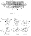
- An inlet 80 communicates with an interior plenum or series of channels 82 . Openings 84 are formed in the external surface 86 of the roller and bearings 90 support opposite ends of the roller for rotation. With this arrangement, it is necessary to synchronise the rotation of the roller with the paper position. Thus, although this type of roller may have more limited applications, it could also be used, for example, to revert a sheet of paper for duplex copying as shown in Figures 8A-F.
- a sheet of paper 60 has a first surface 60' and a second or lower surface 60'' .
- the first surface 60' may have already been printed and it is necessary to print on the second surface 60'' .
- a leading edge 60a of the paper approaches the roller assembly 10 , a circumferentially adjacent pair of quadrants of the roller, and the openings extending through the external surface thereof, are in communication with a source of vacuum (V) .
- V source of vacuum
- the source of vacuum to the first quadrant is changed to a source of pressure (P) .
- P source of pressure
- a vacuum is maintained, however, in the second quadrant so that the trailing edge 60b of the paper is still rotating at the same velocity as that of the roller.
- the change over of the second quadrant from a source of vacuum to a pressure source P as shown in Figure 8D releases the paper from its engagement with the roller.
- the paper has been inverted so that the upper and lower surfaces of the sheet have been reversed from the original position of the paper (Fig. 8A).
- the first and second quadrants are both connected to pressure and an external air jet 92 , or a mechanical member, is urged against the first surface 60' of the sheet. This urges the trailing edge 60b of the sheet upwardly to a position as shown in Figure 8E. Since the first and second quadrants have now passed into communication with the vacuum source, the first surface 60' is then brought into engagement with the roller's surface and the paper adopts the rotational velocity of the roller. Continued rotation of the roller in a clockwise direction to the position shown in Figure 8F completes the reversion process so that the second surface 60'' now faces upwardly and the paper sheet can be transported to a downstream workstation such as an imaging station.
- a downstream workstation such as an imaging station.
Landscapes
- Engineering & Computer Science (AREA)
- Mechanical Engineering (AREA)
- Delivering By Means Of Belts And Rollers (AREA)
- Registering, Tensioning, Guiding Webs, And Rollers Therefor (AREA)
- Advancing Webs (AREA)
Applications Claiming Priority (2)
| Application Number | Priority Date | Filing Date | Title |
|---|---|---|---|
| US24949 | 1998-02-17 | ||
| US09/024,949 US5913268A (en) | 1998-02-17 | 1998-02-17 | Pneumatic rollers and paper handling arrangements |
Publications (3)
| Publication Number | Publication Date |
|---|---|
| EP0936165A2 true EP0936165A2 (de) | 1999-08-18 |
| EP0936165A3 EP0936165A3 (de) | 2000-05-03 |
| EP0936165B1 EP0936165B1 (de) | 2004-09-08 |
Family
ID=21823208
Family Applications (1)
| Application Number | Title | Priority Date | Filing Date |
|---|---|---|---|
| EP99102011A Expired - Lifetime EP0936165B1 (de) | 1998-02-17 | 1999-02-01 | Pneumatische Roller und Papierhandhabungsanordnung |
Country Status (4)
| Country | Link |
|---|---|
| US (1) | US5913268A (de) |
| EP (1) | EP0936165B1 (de) |
| JP (1) | JP4212173B2 (de) |
| DE (1) | DE69919918T2 (de) |
Cited By (1)
| Publication number | Priority date | Publication date | Assignee | Title |
|---|---|---|---|---|
| GB2352689A (en) * | 1999-07-22 | 2001-02-07 | Eastman Kodak Co | Image processing apparatus with vacuum imaging drum having acute-angled vacuum holes |
Families Citing this family (44)
| Publication number | Priority date | Publication date | Assignee | Title |
|---|---|---|---|---|
| EP0769467B1 (de) * | 1995-10-17 | 2002-06-05 | Sharp Kabushiki Kaisha | Bogenausgabevorrichtung |
| AU8990598A (en) | 1997-09-04 | 1999-03-22 | Xaar Technology Limited | Vacuum drums for printing, and duplex printers |
| US6039316A (en) * | 1998-03-02 | 2000-03-21 | Xerox Corporation | Multi-hierarchical control system for controlling object motion with smart matter |
| US6027112A (en) * | 1998-03-02 | 2000-02-22 | Xerox Corporation | Adaptive multiagent control system for controlling object motion with smart matter |
| DE10042885A1 (de) * | 2000-08-31 | 2002-03-14 | Heidelberger Druckmasch Ag | Bogentransportzylinder |
| US6494452B1 (en) * | 2000-10-19 | 2002-12-17 | Krzysztof Karasiewicz | Method and apparatus to decelerate printed product in a stacking process |
| US6442369B1 (en) | 2000-11-27 | 2002-08-27 | Xerox Corporation | Air bearing mechanism for flattening paper in a printing machine |
| US6595512B2 (en) | 2000-12-06 | 2003-07-22 | Xerox Corporation | Constant force sheet feeder |
| DE10208486B4 (de) * | 2001-03-27 | 2012-04-26 | Heidelberger Druckmaschinen Ag | Druckwerk mit einer Vorrichtung zum Entfernen von Partikeln und flächige Bedruckstoffe verarbeitende Maschine mit einem solchen Druckwerk |
| CA2392429C (en) * | 2001-07-23 | 2006-10-10 | Mitsubishi Heavy Industries, Ltd. | Sheet-fed press and intermediate cylinder for sheet-fed press |
| US8857621B2 (en) * | 2001-10-02 | 2014-10-14 | Emerging Acquisitions, Llc | De-inking screen with air knife |
| PT1458499E (pt) * | 2001-10-02 | 2007-04-30 | Emerging Acquisitions Llc | Tela |
| EP1321403A1 (de) * | 2001-12-20 | 2003-06-25 | Mars Incorporated | Verfahren und Vorrichtung zur Ausrichtung einer Banknote |
| DE10310690A1 (de) * | 2002-04-12 | 2003-10-30 | Heidelberger Druckmasch Ag | Bogenführungseinrichtung in einer bogenverarbeitenden Maschine |
| GB0220470D0 (en) * | 2002-09-03 | 2002-10-09 | Xaar Technology Ltd | Valve member |
| US7530938B2 (en) * | 2003-07-01 | 2009-05-12 | Illinois Tool Works Inc. | Pneumatic roller for passing film with attachments through rollers of machine |
| US7077019B2 (en) * | 2003-08-08 | 2006-07-18 | Photon Dynamics, Inc. | High precision gas bearing split-axis stage for transport and constraint of large flat flexible media during processing |
| GB0410640D0 (en) * | 2004-05-13 | 2004-06-16 | Koninkl Philips Electronics Nv | Support guide |
| US20060261120A1 (en) * | 2005-05-03 | 2006-11-23 | Slyne William J | Method and apparatus to continuously separate cut pieces from flexible material |
| CA2546191C (en) * | 2005-06-06 | 2010-05-18 | Ambrus L. Varga | Insulated vent cap |
| FR2899243B1 (fr) * | 2006-03-30 | 2008-05-16 | Saint Gobain Vetrotex | Procede et dispositif de fabrication d'un fil composite |
| US7942273B2 (en) * | 2008-10-07 | 2011-05-17 | Emerging Acquisitions, Llc | Cross flow air separation system |
| US8307987B2 (en) * | 2006-11-03 | 2012-11-13 | Emerging Acquisitions, Llc | Electrostatic material separator |
| US7766569B2 (en) * | 2007-01-30 | 2010-08-03 | Hewlett-Packard Development Company, L.P. | Method for reducing media skew in a media advance mechanism |
| US8618432B2 (en) * | 2007-12-18 | 2013-12-31 | Emerging Acquisitions, Llc | Separation system for recyclable material |
| US8028988B2 (en) * | 2008-01-21 | 2011-10-04 | Honeywell International Inc. | Apparatus and method for stabilizing a moving sheet relative to a sensor |
| JP4702706B2 (ja) * | 2008-09-11 | 2011-06-15 | ブラザー工業株式会社 | プリンタ |
| US8123222B2 (en) * | 2009-05-01 | 2012-02-28 | Pitney Bowes Inc. | Compliant conveyance system for mailpiece transport along an arcuate feed path |
| US8336714B2 (en) * | 2009-05-14 | 2012-12-25 | Emerging Acquistions, LLC | Heating system for material processing screen |
| US8398231B2 (en) * | 2009-08-21 | 2013-03-19 | Zamtec Ltd | Continuous web printer with upper and lower print zones for opposing sides of web |
| US20120157279A1 (en) * | 2010-12-20 | 2012-06-21 | Uwe Schneider | Process and Apparatus for Joining Flexible Components |
| US8833250B2 (en) | 2011-03-04 | 2014-09-16 | The Procter & Gamble Company | Apparatus for applying indicia having a large color gamut on web substrates |
| US8839716B2 (en) | 2011-03-04 | 2014-09-23 | The Procter & Gamble Company | Apparatus for applying indicia having a large color gamut on web substrates |
| US8943959B2 (en) * | 2011-03-04 | 2015-02-03 | The Procter & Gamble Company | Unique process for printing multiple color indicia upon web substrates |
| US8943957B2 (en) | 2011-03-04 | 2015-02-03 | The Procter & Gamble Company | Apparatus for applying indicia having a large color gamut on web substrates |
| US8985013B2 (en) | 2011-03-04 | 2015-03-24 | The Procter & Gamble Company | Apparatus for applying indicia having a large color gamut on web substrates |
| CN103008187B (zh) * | 2012-12-26 | 2015-04-08 | 海南赛诺实业有限公司 | 一种用于双面涂布膜的翻转系统 |
| CN103964235B (zh) * | 2012-12-28 | 2016-08-31 | 财团法人金属工业研究发展中心 | 线性翻转机构及真空设备 |
| US10011450B2 (en) * | 2015-08-17 | 2018-07-03 | C.G. Bretting Manufacturing Co., Inc. | Web processing roll having directional vacuum ports |
| US10111385B2 (en) | 2016-06-24 | 2018-10-30 | Jackrabbit | Nut harvester with separating disks |
| GB2568767B (en) * | 2017-12-18 | 2022-10-05 | Loop Tech Ltd | A system for handling flexible material |
| AU2020218530A1 (en) | 2019-02-08 | 2021-08-12 | Jackrabbit, Inc. | A nut harvester with a removable assembly and a method of replacing a removable assembly of a nut harvester |
| JP7807455B2 (ja) * | 2021-08-16 | 2026-01-27 | 富士フイルム株式会社 | エアバー、乾燥装置、及びインクジェット印刷装置 |
| JP2024088903A (ja) * | 2022-12-21 | 2024-07-03 | 京セラドキュメントソリューションズ株式会社 | 搬送ローラー、ウェブ搬送装置、画像形成装置 |
Family Cites Families (30)
| Publication number | Priority date | Publication date | Assignee | Title |
|---|---|---|---|---|
| US32541A (en) * | 1861-06-11 | Tubular grate for steam-boilers | ||
| DE2348320C3 (de) * | 1973-09-26 | 1978-12-14 | Vits-Maschinenbau Gmbh, 4018 Langenfeld | Vorrichtung zum stapelweisen Ablegen einzelner gleichlanger Bogen |
| CH598110A5 (de) * | 1975-10-10 | 1978-04-28 | Gretag Ag | |
| USRE32541E (en) | 1976-01-15 | 1987-11-10 | Xerox Corporation | Fluidic feeding of documents to an exposure station |
| US4062538A (en) * | 1976-01-15 | 1977-12-13 | Xerox Corporation | Speed regulated fluidic sheet transport |
| US4207998A (en) * | 1977-05-16 | 1980-06-17 | Bachofen & Meier, Maschinenfabrik | Vacuum roller |
| DE2737882A1 (de) * | 1977-08-23 | 1979-03-01 | Voith Gmbh J M | Zylinder fuer maschinen zur herstellung von faserbahnen |
| FR2489798A1 (fr) * | 1980-09-05 | 1982-03-12 | Hotchkiss Brandt Sogeme | Dispositif d'empilage d'objets minces et flexibles |
| DE3131388A1 (de) * | 1981-08-07 | 1983-02-24 | GAO Gesellschaft für Automation und Organisation mbH, 8000 München | Stapelvorrichtung fuer blattgut |
| US4493548A (en) * | 1982-03-26 | 1985-01-15 | Eastman Kodak Company | Apparatus for supporting flexible members |
| DE3328451A1 (de) * | 1983-08-06 | 1985-02-21 | Heidelberger Druckmaschinen Ag, 6900 Heidelberg | Abschmierfreie umfuehrtrommel fuer bogentotationsdruckmaschinen |
| FI67901C (fi) * | 1983-10-03 | 1987-07-20 | Valmet Oy | Foerfarande och anordning i torkpartiet i en pappersmaskin vid styrning av banans spets. |
| US4792249A (en) * | 1985-09-20 | 1988-12-20 | Creative Associates Limited Partnership | Vacuum paper transport system for printer |
| US4726502A (en) * | 1986-07-07 | 1988-02-23 | Cryderman Gary G | Apparatus for entraining and directing a wet paper web |
| US5032875A (en) * | 1986-12-19 | 1991-07-16 | Xerox Corporation | Heat extraction transport roll with annulus |
| ATE89227T1 (de) * | 1987-01-14 | 1993-05-15 | Alfred Alexander Taylor | Filmantriebseinheit fuer eine verpackungsmaschine. |
| US4997178A (en) * | 1988-04-01 | 1991-03-05 | Fuji Photo Film Co., Ltd. | Method of and mechanism for feeding sheet |
| DE3901907C1 (de) * | 1989-01-24 | 1990-03-22 | Heidelberger Druckmaschinen Ag, 6900 Heidelberg, De | |
| DE3914761A1 (de) * | 1989-03-08 | 1990-11-15 | Voith Gmbh J M | Leitwalze fuer ein poroeses band, beispielsweise fuer ein trockensieb einer papiermaschine |
| US5197812A (en) * | 1989-11-09 | 1993-03-30 | Dataproducts Corporation | High accuracy vacuum belt and pinch roller media transport mechanism |
| US5186451A (en) * | 1990-01-18 | 1993-02-16 | Fujitsu Limited | Sheet paper feed apparatus having vacuum feed rollers |
| JP2640579B2 (ja) * | 1990-08-27 | 1997-08-13 | 富士写真フイルム株式会社 | 包装シート巻付装置 |
| US5127329A (en) * | 1990-12-18 | 1992-07-07 | Howard W. DeMoore | Vacuum transfer apparatus for rotary sheet-fed printing presses |
| DE4117388C2 (de) * | 1991-05-28 | 1994-04-28 | Koenig & Bauer Ag | Walze zum Führen einer Warenbahn |
| EP0576810B1 (de) * | 1992-05-29 | 1996-09-18 | Heidelberger Druckmaschinen Aktiengesellschaft | Einrichtung zur Unterstützung des kontrollierten Exemplartransportes im Falzapparat von Rotationsdruckmaschinen |
| US5402721A (en) * | 1993-05-13 | 1995-04-04 | Comco Machinery, Inc. | Vacuum printing plate roller |
| DE4332708C2 (de) * | 1993-09-25 | 2000-05-04 | Heidelberger Druckmasch Ag | Vorrichtung zum abschmierfreien Bogentransport in Bogendruckmaschinen |
| EP0663360B1 (de) * | 1994-01-17 | 2000-04-12 | Heidelberger Druckmaschinen Aktiengesellschaft | Bogenführungszylinder |
| US5431384A (en) * | 1994-05-10 | 1995-07-11 | Polaroid Corporation | Method and apparatus for feeding print media |
| DE19503110B4 (de) * | 1995-02-01 | 2009-01-29 | Heidelberger Druckmaschinen Ag | Bogenleiteinrichtung für Druckmaschinen |
-
1998
- 1998-02-17 US US09/024,949 patent/US5913268A/en not_active Expired - Lifetime
-
1999
- 1999-02-01 DE DE69919918T patent/DE69919918T2/de not_active Expired - Lifetime
- 1999-02-01 EP EP99102011A patent/EP0936165B1/de not_active Expired - Lifetime
- 1999-02-04 JP JP02683399A patent/JP4212173B2/ja not_active Expired - Fee Related
Cited By (1)
| Publication number | Priority date | Publication date | Assignee | Title |
|---|---|---|---|---|
| GB2352689A (en) * | 1999-07-22 | 2001-02-07 | Eastman Kodak Co | Image processing apparatus with vacuum imaging drum having acute-angled vacuum holes |
Also Published As
| Publication number | Publication date |
|---|---|
| EP0936165B1 (de) | 2004-09-08 |
| EP0936165A3 (de) | 2000-05-03 |
| DE69919918D1 (de) | 2004-10-14 |
| JP4212173B2 (ja) | 2009-01-21 |
| DE69919918T2 (de) | 2005-01-20 |
| JPH11263478A (ja) | 1999-09-28 |
| US5913268A (en) | 1999-06-22 |
Similar Documents
| Publication | Publication Date | Title |
|---|---|---|
| US5913268A (en) | Pneumatic rollers and paper handling arrangements | |
| US6912952B1 (en) | Duplex printing system | |
| US5186107A (en) | Drum for transporting sheets | |
| US4955965A (en) | Positive drive, passive, sheet rotation device using differential roll velocities | |
| EP1457444B2 (de) | Maschine zum Ineinanderfalten einer Bahn oder von Blättern mit einer Vakuumtransportwalze | |
| US7735829B2 (en) | Method and apparatus for turning a sheet during its transport through a printing press | |
| US6688594B2 (en) | Suction roll | |
| JP4847637B2 (ja) | 刷り本の速度を変更するための装置 | |
| JP2647186B2 (ja) | 積層シートの分離装置 | |
| US5236188A (en) | Apparatus and method for delivering printed products in a rotary printing press | |
| EP0644138B1 (de) | Fördervorrichtung für Bögen mit, auf den Bögen wirkende, variabler Förderkraft | |
| US3779546A (en) | Vacuum wheel document direction changing device | |
| US5358233A (en) | Sheet delivery in a printing machine | |
| JP3273659B2 (ja) | 輪転印刷機の折りたたみ装置中の、刷り本案内胴の間で刷り本を案内する装置 | |
| JP2000095407A (ja) | 折丁変向装置 | |
| JPH0281870A (ja) | 輪転印刷機の折り装置中で刷り本断片を案内する装置 | |
| JPH09142692A (ja) | 枚葉紙を搬送する装置 | |
| JPH0259096B2 (de) | ||
| WO2001034396A1 (en) | Duplex printing system | |
| EP1244549B1 (de) | Duplexdrucksystem | |
| CN1216501A (zh) | 用于印刷机、特别是旋转式胶印机的翻转装置 | |
| EP0537017B1 (de) | Vorrichtung zum zeitlichen Ausrichten mit laufender Ausrichtkante | |
| US6605027B1 (en) | Fold-off guide for a folder in a paper-processing machine | |
| JPH0930668A (ja) | 自動給紙機構 | |
| JPH07267455A (ja) | 媒体搬送装置 |
Legal Events
| Date | Code | Title | Description |
|---|---|---|---|
| PUAI | Public reference made under article 153(3) epc to a published international application that has entered the european phase |
Free format text: ORIGINAL CODE: 0009012 |
|
| AK | Designated contracting states |
Kind code of ref document: A2 Designated state(s): DE FR GB |
|
| AX | Request for extension of the european patent |
Free format text: AL;LT;LV;MK;RO;SI |
|
| PUAL | Search report despatched |
Free format text: ORIGINAL CODE: 0009013 |
|
| AK | Designated contracting states |
Kind code of ref document: A3 Designated state(s): AT BE CH CY DE DK ES FI FR GB GR IE IT LI LU MC NL PT SE |
|
| AX | Request for extension of the european patent |
Free format text: AL;LT;LV;MK;RO;SI |
|
| 17P | Request for examination filed |
Effective date: 20001103 |
|
| AKX | Designation fees paid |
Free format text: DE FR GB |
|
| 17Q | First examination report despatched |
Effective date: 20020902 |
|
| GRAP | Despatch of communication of intention to grant a patent |
Free format text: ORIGINAL CODE: EPIDOSNIGR1 |
|
| GRAS | Grant fee paid |
Free format text: ORIGINAL CODE: EPIDOSNIGR3 |
|
| GRAA | (expected) grant |
Free format text: ORIGINAL CODE: 0009210 |
|
| AK | Designated contracting states |
Kind code of ref document: B1 Designated state(s): DE FR GB |
|
| REG | Reference to a national code |
Ref country code: GB Ref legal event code: FG4D |
|
| REF | Corresponds to: |
Ref document number: 69919918 Country of ref document: DE Date of ref document: 20041014 Kind code of ref document: P |
|
| ET | Fr: translation filed | ||
| PLBE | No opposition filed within time limit |
Free format text: ORIGINAL CODE: 0009261 |
|
| STAA | Information on the status of an ep patent application or granted ep patent |
Free format text: STATUS: NO OPPOSITION FILED WITHIN TIME LIMIT |
|
| 26N | No opposition filed |
Effective date: 20050609 |
|
| REG | Reference to a national code |
Ref country code: FR Ref legal event code: PLFP Year of fee payment: 18 |
|
| PGFP | Annual fee paid to national office [announced via postgrant information from national office to epo] |
Ref country code: DE Payment date: 20160121 Year of fee payment: 18 |
|
| PGFP | Annual fee paid to national office [announced via postgrant information from national office to epo] |
Ref country code: GB Payment date: 20160127 Year of fee payment: 18 Ref country code: FR Payment date: 20160121 Year of fee payment: 18 |
|
| REG | Reference to a national code |
Ref country code: DE Ref legal event code: R119 Ref document number: 69919918 Country of ref document: DE |
|
| GBPC | Gb: european patent ceased through non-payment of renewal fee |
Effective date: 20170201 |
|
| REG | Reference to a national code |
Ref country code: FR Ref legal event code: ST Effective date: 20171031 |
|
| PG25 | Lapsed in a contracting state [announced via postgrant information from national office to epo] |
Ref country code: FR Free format text: LAPSE BECAUSE OF NON-PAYMENT OF DUE FEES Effective date: 20170228 Ref country code: DE Free format text: LAPSE BECAUSE OF NON-PAYMENT OF DUE FEES Effective date: 20170901 |
|
| PG25 | Lapsed in a contracting state [announced via postgrant information from national office to epo] |
Ref country code: GB Free format text: LAPSE BECAUSE OF NON-PAYMENT OF DUE FEES Effective date: 20170201 |