EP0936521A2 - Integriertes Fahrzeugpositionier- und -navigationssystem, dessen Vorrichtung und Verfahren - Google Patents
Integriertes Fahrzeugpositionier- und -navigationssystem, dessen Vorrichtung und Verfahren Download PDFInfo
- Publication number
- EP0936521A2 EP0936521A2 EP99106275A EP99106275A EP0936521A2 EP 0936521 A2 EP0936521 A2 EP 0936521A2 EP 99106275 A EP99106275 A EP 99106275A EP 99106275 A EP99106275 A EP 99106275A EP 0936521 A2 EP0936521 A2 EP 0936521A2
- Authority
- EP
- European Patent Office
- Prior art keywords
- vehicle
- gps
- data
- path
- steering
- Prior art date
- Legal status (The legal status is an assumption and is not a legal conclusion. Google has not performed a legal analysis and makes no representation as to the accuracy of the status listed.)
- Withdrawn
Links
Images
































Classifications
-
- G—PHYSICS
- G01—MEASURING; TESTING
- G01S—RADIO DIRECTION-FINDING; RADIO NAVIGATION; DETERMINING DISTANCE OR VELOCITY BY USE OF RADIO WAVES; LOCATING OR PRESENCE-DETECTING BY USE OF THE REFLECTION OR RERADIATION OF RADIO WAVES; ANALOGOUS ARRANGEMENTS USING OTHER WAVES
- G01S19/00—Satellite radio beacon positioning systems; Determining position, velocity or attitude using signals transmitted by such systems
- G01S19/38—Determining a navigation solution using signals transmitted by a satellite radio beacon positioning system
- G01S19/39—Determining a navigation solution using signals transmitted by a satellite radio beacon positioning system the satellite radio beacon positioning system transmitting time-stamped messages, e.g. GPS [Global Positioning System], GLONASS [Global Orbiting Navigation Satellite System] or GALILEO
- G01S19/42—Determining position
- G01S19/45—Determining position by combining measurements of signals from the satellite radio beacon positioning system with a supplementary measurement
- G01S19/47—Determining position by combining measurements of signals from the satellite radio beacon positioning system with a supplementary measurement the supplementary measurement being an inertial measurement, e.g. tightly coupled inertial
-
- G—PHYSICS
- G01—MEASURING; TESTING
- G01S—RADIO DIRECTION-FINDING; RADIO NAVIGATION; DETERMINING DISTANCE OR VELOCITY BY USE OF RADIO WAVES; LOCATING OR PRESENCE-DETECTING BY USE OF THE REFLECTION OR RERADIATION OF RADIO WAVES; ANALOGOUS ARRANGEMENTS USING OTHER WAVES
- G01S19/00—Satellite radio beacon positioning systems; Determining position, velocity or attitude using signals transmitted by such systems
- G01S19/01—Satellite radio beacon positioning systems transmitting time-stamped messages, e.g. GPS [Global Positioning System], GLONASS [Global Orbiting Navigation Satellite System] or GALILEO
- G01S19/03—Cooperating elements; Interaction or communication between different cooperating elements or between cooperating elements and receivers
- G01S19/10—Cooperating elements; Interaction or communication between different cooperating elements or between cooperating elements and receivers providing dedicated supplementary positioning signals
- G01S19/11—Cooperating elements; Interaction or communication between different cooperating elements or between cooperating elements and receivers providing dedicated supplementary positioning signals wherein the cooperating elements are pseudolites or satellite radio beacon positioning system signal repeaters
-
- B—PERFORMING OPERATIONS; TRANSPORTING
- B60—VEHICLES IN GENERAL
- B60K—ARRANGEMENT OR MOUNTING OF PROPULSION UNITS OR OF TRANSMISSIONS IN VEHICLES; ARRANGEMENT OR MOUNTING OF PLURAL DIVERSE PRIME-MOVERS IN VEHICLES; AUXILIARY DRIVES FOR VEHICLES; INSTRUMENTATION OR DASHBOARDS FOR VEHICLES; ARRANGEMENTS IN CONNECTION WITH COOLING, AIR INTAKE, GAS EXHAUST OR FUEL SUPPLY OF PROPULSION UNITS IN VEHICLES
- B60K31/00—Vehicle fittings, acting on a single sub-unit only, for automatically controlling vehicle speed, i.e. preventing speed from exceeding an arbitrarily established velocity or maintaining speed at a particular velocity, as selected by the vehicle operator
- B60K31/0008—Vehicle fittings, acting on a single sub-unit only, for automatically controlling vehicle speed, i.e. preventing speed from exceeding an arbitrarily established velocity or maintaining speed at a particular velocity, as selected by the vehicle operator including means for detecting potential obstacles in vehicle path
-
- B—PERFORMING OPERATIONS; TRANSPORTING
- B60—VEHICLES IN GENERAL
- B60K—ARRANGEMENT OR MOUNTING OF PROPULSION UNITS OR OF TRANSMISSIONS IN VEHICLES; ARRANGEMENT OR MOUNTING OF PLURAL DIVERSE PRIME-MOVERS IN VEHICLES; AUXILIARY DRIVES FOR VEHICLES; INSTRUMENTATION OR DASHBOARDS FOR VEHICLES; ARRANGEMENTS IN CONNECTION WITH COOLING, AIR INTAKE, GAS EXHAUST OR FUEL SUPPLY OF PROPULSION UNITS IN VEHICLES
- B60K31/00—Vehicle fittings, acting on a single sub-unit only, for automatically controlling vehicle speed, i.e. preventing speed from exceeding an arbitrarily established velocity or maintaining speed at a particular velocity, as selected by the vehicle operator
- B60K31/02—Vehicle fittings, acting on a single sub-unit only, for automatically controlling vehicle speed, i.e. preventing speed from exceeding an arbitrarily established velocity or maintaining speed at a particular velocity, as selected by the vehicle operator including electrically actuated servomechanism
- B60K31/04—Vehicle fittings, acting on a single sub-unit only, for automatically controlling vehicle speed, i.e. preventing speed from exceeding an arbitrarily established velocity or maintaining speed at a particular velocity, as selected by the vehicle operator including electrically actuated servomechanism and means for comparing one electrical quantity, e.g. voltage, pulse, waveform, flux, or the like, with another quantity of a like kind, which comparison means is involved in the development of an electrical signal which is fed into the controlling means
-
- B—PERFORMING OPERATIONS; TRANSPORTING
- B60—VEHICLES IN GENERAL
- B60W—CONJOINT CONTROL OF VEHICLE SUB-UNITS OF DIFFERENT TYPE OR DIFFERENT FUNCTION; CONTROL SYSTEMS SPECIALLY ADAPTED FOR HYBRID VEHICLES; ROAD VEHICLE DRIVE CONTROL SYSTEMS FOR PURPOSES NOT RELATED TO THE CONTROL OF A PARTICULAR SUB-UNIT
- B60W60/00—Drive control systems specially adapted for autonomous road vehicles
- B60W60/001—Planning or execution of driving tasks
- B60W60/0011—Planning or execution of driving tasks involving control alternatives for a single driving scenario, e.g. planning several paths to avoid obstacles
-
- G—PHYSICS
- G01—MEASURING; TESTING
- G01C—MEASURING DISTANCES, LEVELS OR BEARINGS; SURVEYING; NAVIGATION; GYROSCOPIC INSTRUMENTS; PHOTOGRAMMETRY OR VIDEOGRAMMETRY
- G01C21/00—Navigation; Navigational instruments not provided for in groups G01C1/00 - G01C19/00
- G01C21/10—Navigation; Navigational instruments not provided for in groups G01C1/00 - G01C19/00 by using measurements of speed or acceleration
- G01C21/12—Navigation; Navigational instruments not provided for in groups G01C1/00 - G01C19/00 by using measurements of speed or acceleration executed aboard the object being navigated; Dead reckoning
- G01C21/16—Navigation; Navigational instruments not provided for in groups G01C1/00 - G01C19/00 by using measurements of speed or acceleration executed aboard the object being navigated; Dead reckoning by integrating acceleration or speed, i.e. inertial navigation
- G01C21/165—Navigation; Navigational instruments not provided for in groups G01C1/00 - G01C19/00 by using measurements of speed or acceleration executed aboard the object being navigated; Dead reckoning by integrating acceleration or speed, i.e. inertial navigation combined with non-inertial navigation instruments
-
- G—PHYSICS
- G01—MEASURING; TESTING
- G01C—MEASURING DISTANCES, LEVELS OR BEARINGS; SURVEYING; NAVIGATION; GYROSCOPIC INSTRUMENTS; PHOTOGRAMMETRY OR VIDEOGRAMMETRY
- G01C21/00—Navigation; Navigational instruments not provided for in groups G01C1/00 - G01C19/00
- G01C21/26—Navigation; Navigational instruments not provided for in groups G01C1/00 - G01C19/00 specially adapted for navigation in a road network
- G01C21/28—Navigation; Navigational instruments not provided for in groups G01C1/00 - G01C19/00 specially adapted for navigation in a road network with correlation of data from several navigational instruments
-
- G—PHYSICS
- G01—MEASURING; TESTING
- G01S—RADIO DIRECTION-FINDING; RADIO NAVIGATION; DETERMINING DISTANCE OR VELOCITY BY USE OF RADIO WAVES; LOCATING OR PRESENCE-DETECTING BY USE OF THE REFLECTION OR RERADIATION OF RADIO WAVES; ANALOGOUS ARRANGEMENTS USING OTHER WAVES
- G01S19/00—Satellite radio beacon positioning systems; Determining position, velocity or attitude using signals transmitted by such systems
- G01S19/38—Determining a navigation solution using signals transmitted by a satellite radio beacon positioning system
- G01S19/39—Determining a navigation solution using signals transmitted by a satellite radio beacon positioning system the satellite radio beacon positioning system transmitting time-stamped messages, e.g. GPS [Global Positioning System], GLONASS [Global Orbiting Navigation Satellite System] or GALILEO
- G01S19/40—Correcting position, velocity or attitude
- G01S19/41—Differential correction, e.g. DGPS [differential GPS]
-
- G—PHYSICS
- G01—MEASURING; TESTING
- G01S—RADIO DIRECTION-FINDING; RADIO NAVIGATION; DETERMINING DISTANCE OR VELOCITY BY USE OF RADIO WAVES; LOCATING OR PRESENCE-DETECTING BY USE OF THE REFLECTION OR RERADIATION OF RADIO WAVES; ANALOGOUS ARRANGEMENTS USING OTHER WAVES
- G01S19/00—Satellite radio beacon positioning systems; Determining position, velocity or attitude using signals transmitted by such systems
- G01S19/38—Determining a navigation solution using signals transmitted by a satellite radio beacon positioning system
- G01S19/39—Determining a navigation solution using signals transmitted by a satellite radio beacon positioning system the satellite radio beacon positioning system transmitting time-stamped messages, e.g. GPS [Global Positioning System], GLONASS [Global Orbiting Navigation Satellite System] or GALILEO
- G01S19/42—Determining position
- G01S19/45—Determining position by combining measurements of signals from the satellite radio beacon positioning system with a supplementary measurement
- G01S19/46—Determining position by combining measurements of signals from the satellite radio beacon positioning system with a supplementary measurement the supplementary measurement being of a radio-wave signal type
-
- G—PHYSICS
- G01—MEASURING; TESTING
- G01S—RADIO DIRECTION-FINDING; RADIO NAVIGATION; DETERMINING DISTANCE OR VELOCITY BY USE OF RADIO WAVES; LOCATING OR PRESENCE-DETECTING BY USE OF THE REFLECTION OR RERADIATION OF RADIO WAVES; ANALOGOUS ARRANGEMENTS USING OTHER WAVES
- G01S19/00—Satellite radio beacon positioning systems; Determining position, velocity or attitude using signals transmitted by such systems
- G01S19/38—Determining a navigation solution using signals transmitted by a satellite radio beacon positioning system
- G01S19/39—Determining a navigation solution using signals transmitted by a satellite radio beacon positioning system the satellite radio beacon positioning system transmitting time-stamped messages, e.g. GPS [Global Positioning System], GLONASS [Global Orbiting Navigation Satellite System] or GALILEO
- G01S19/42—Determining position
- G01S19/48—Determining position by combining or switching between position solutions derived from the satellite radio beacon positioning system and position solutions derived from a further system
- G01S19/49—Determining position by combining or switching between position solutions derived from the satellite radio beacon positioning system and position solutions derived from a further system whereby the further system is an inertial position system, e.g. loosely-coupled
-
- G—PHYSICS
- G01—MEASURING; TESTING
- G01S—RADIO DIRECTION-FINDING; RADIO NAVIGATION; DETERMINING DISTANCE OR VELOCITY BY USE OF RADIO WAVES; LOCATING OR PRESENCE-DETECTING BY USE OF THE REFLECTION OR RERADIATION OF RADIO WAVES; ANALOGOUS ARRANGEMENTS USING OTHER WAVES
- G01S7/00—Details of systems according to groups G01S13/00, G01S15/00, G01S17/00
- G01S7/48—Details of systems according to groups G01S13/00, G01S15/00, G01S17/00 of systems according to group G01S17/00
- G01S7/481—Constructional features, e.g. arrangements of optical elements
- G01S7/4811—Constructional features, e.g. arrangements of optical elements common to transmitter and receiver
-
- G—PHYSICS
- G01—MEASURING; TESTING
- G01S—RADIO DIRECTION-FINDING; RADIO NAVIGATION; DETERMINING DISTANCE OR VELOCITY BY USE OF RADIO WAVES; LOCATING OR PRESENCE-DETECTING BY USE OF THE REFLECTION OR RERADIATION OF RADIO WAVES; ANALOGOUS ARRANGEMENTS USING OTHER WAVES
- G01S7/00—Details of systems according to groups G01S13/00, G01S15/00, G01S17/00
- G01S7/48—Details of systems according to groups G01S13/00, G01S15/00, G01S17/00 of systems according to group G01S17/00
- G01S7/497—Means for monitoring or calibrating
-
- G—PHYSICS
- G05—CONTROLLING; REGULATING
- G05D—SYSTEMS FOR CONTROLLING OR REGULATING NON-ELECTRIC VARIABLES
- G05D1/00—Control of position, course, altitude or attitude of land, water, air or space vehicles, e.g. using automatic pilots
-
- G—PHYSICS
- G05—CONTROLLING; REGULATING
- G05D—SYSTEMS FOR CONTROLLING OR REGULATING NON-ELECTRIC VARIABLES
- G05D1/00—Control of position, course, altitude or attitude of land, water, air or space vehicles, e.g. using automatic pilots
- G05D1/20—Control system inputs
- G05D1/22—Command input arrangements
- G05D1/221—Remote-control arrangements
- G05D1/227—Handing over between remote control and on-board control; Handing over between remote control arrangements
-
- G—PHYSICS
- G05—CONTROLLING; REGULATING
- G05D—SYSTEMS FOR CONTROLLING OR REGULATING NON-ELECTRIC VARIABLES
- G05D1/00—Control of position, course, altitude or attitude of land, water, air or space vehicles, e.g. using automatic pilots
- G05D1/20—Control system inputs
- G05D1/24—Arrangements for determining position or orientation
- G05D1/242—Means based on the reflection of waves generated by the vehicle
-
- G—PHYSICS
- G05—CONTROLLING; REGULATING
- G05D—SYSTEMS FOR CONTROLLING OR REGULATING NON-ELECTRIC VARIABLES
- G05D1/00—Control of position, course, altitude or attitude of land, water, air or space vehicles, e.g. using automatic pilots
- G05D1/20—Control system inputs
- G05D1/24—Arrangements for determining position or orientation
- G05D1/247—Arrangements for determining position or orientation using signals provided by artificial sources external to the vehicle, e.g. navigation beacons
- G05D1/248—Arrangements for determining position or orientation using signals provided by artificial sources external to the vehicle, e.g. navigation beacons generated by satellites, e.g. GPS
-
- G—PHYSICS
- G05—CONTROLLING; REGULATING
- G05D—SYSTEMS FOR CONTROLLING OR REGULATING NON-ELECTRIC VARIABLES
- G05D1/00—Control of position, course, altitude or attitude of land, water, air or space vehicles, e.g. using automatic pilots
- G05D1/60—Intended control result
- G05D1/617—Safety or protection, e.g. defining protection zones around obstacles or avoiding hazards
- G05D1/622—Obstacle avoidance
-
- G—PHYSICS
- G05—CONTROLLING; REGULATING
- G05D—SYSTEMS FOR CONTROLLING OR REGULATING NON-ELECTRIC VARIABLES
- G05D1/00—Control of position, course, altitude or attitude of land, water, air or space vehicles, e.g. using automatic pilots
- G05D1/60—Intended control result
- G05D1/646—Following a predefined trajectory, e.g. a line marked on the floor or a flight path
-
- G—PHYSICS
- G05—CONTROLLING; REGULATING
- G05D—SYSTEMS FOR CONTROLLING OR REGULATING NON-ELECTRIC VARIABLES
- G05D1/00—Control of position, course, altitude or attitude of land, water, air or space vehicles, e.g. using automatic pilots
- G05D1/80—Arrangements for reacting to or preventing system or operator failure
- G05D1/81—Handing over between on-board automatic and on-board manual control
-
- G—PHYSICS
- G08—SIGNALLING
- G08G—TRAFFIC CONTROL SYSTEMS
- G08G1/00—Traffic control systems for road vehicles
- G08G1/20—Monitoring the location of vehicles belonging to a group, e.g. fleet of vehicles, countable or determined number of vehicles
-
- G—PHYSICS
- G11—INFORMATION STORAGE
- G11B—INFORMATION STORAGE BASED ON RELATIVE MOVEMENT BETWEEN RECORD CARRIER AND TRANSDUCER
- G11B5/00—Recording by magnetisation or demagnetisation of a record carrier; Reproducing by magnetic means; Record carriers therefor
- G11B5/10—Structure or manufacture of housings or shields for heads
- G11B5/105—Mounting of head within housing or assembling of head and housing
-
- B—PERFORMING OPERATIONS; TRANSPORTING
- B60—VEHICLES IN GENERAL
- B60W—CONJOINT CONTROL OF VEHICLE SUB-UNITS OF DIFFERENT TYPE OR DIFFERENT FUNCTION; CONTROL SYSTEMS SPECIALLY ADAPTED FOR HYBRID VEHICLES; ROAD VEHICLE DRIVE CONTROL SYSTEMS FOR PURPOSES NOT RELATED TO THE CONTROL OF A PARTICULAR SUB-UNIT
- B60W2554/00—Input parameters relating to objects
-
- B—PERFORMING OPERATIONS; TRANSPORTING
- B60—VEHICLES IN GENERAL
- B60W—CONJOINT CONTROL OF VEHICLE SUB-UNITS OF DIFFERENT TYPE OR DIFFERENT FUNCTION; CONTROL SYSTEMS SPECIALLY ADAPTED FOR HYBRID VEHICLES; ROAD VEHICLE DRIVE CONTROL SYSTEMS FOR PURPOSES NOT RELATED TO THE CONTROL OF A PARTICULAR SUB-UNIT
- B60W2554/00—Input parameters relating to objects
- B60W2554/20—Static objects
-
- B—PERFORMING OPERATIONS; TRANSPORTING
- B60—VEHICLES IN GENERAL
- B60W—CONJOINT CONTROL OF VEHICLE SUB-UNITS OF DIFFERENT TYPE OR DIFFERENT FUNCTION; CONTROL SYSTEMS SPECIALLY ADAPTED FOR HYBRID VEHICLES; ROAD VEHICLE DRIVE CONTROL SYSTEMS FOR PURPOSES NOT RELATED TO THE CONTROL OF A PARTICULAR SUB-UNIT
- B60W2556/00—Input parameters relating to data
- B60W2556/45—External transmission of data to or from the vehicle
- B60W2556/50—External transmission of data to or from the vehicle of positioning data, e.g. GPS [Global Positioning System] data
-
- B—PERFORMING OPERATIONS; TRANSPORTING
- B60—VEHICLES IN GENERAL
- B60Y—INDEXING SCHEME RELATING TO ASPECTS CROSS-CUTTING VEHICLE TECHNOLOGY
- B60Y2200/00—Type of vehicle
- B60Y2200/40—Special vehicles
- B60Y2200/41—Construction vehicles, e.g. graders, excavators
-
- G—PHYSICS
- G01—MEASURING; TESTING
- G01S—RADIO DIRECTION-FINDING; RADIO NAVIGATION; DETERMINING DISTANCE OR VELOCITY BY USE OF RADIO WAVES; LOCATING OR PRESENCE-DETECTING BY USE OF THE REFLECTION OR RERADIATION OF RADIO WAVES; ANALOGOUS ARRANGEMENTS USING OTHER WAVES
- G01S17/00—Systems using the reflection or reradiation of electromagnetic waves other than radio waves, e.g. lidar systems
- G01S17/02—Systems using the reflection of electromagnetic waves other than radio waves
- G01S17/06—Systems determining position data of a target
- G01S17/42—Simultaneous measurement of distance and other co-ordinates
-
- G—PHYSICS
- G01—MEASURING; TESTING
- G01S—RADIO DIRECTION-FINDING; RADIO NAVIGATION; DETERMINING DISTANCE OR VELOCITY BY USE OF RADIO WAVES; LOCATING OR PRESENCE-DETECTING BY USE OF THE REFLECTION OR RERADIATION OF RADIO WAVES; ANALOGOUS ARRANGEMENTS USING OTHER WAVES
- G01S17/00—Systems using the reflection or reradiation of electromagnetic waves other than radio waves, e.g. lidar systems
- G01S17/86—Combinations of lidar systems with systems other than lidar, radar or sonar, e.g. with direction finders
-
- G—PHYSICS
- G01—MEASURING; TESTING
- G01S—RADIO DIRECTION-FINDING; RADIO NAVIGATION; DETERMINING DISTANCE OR VELOCITY BY USE OF RADIO WAVES; LOCATING OR PRESENCE-DETECTING BY USE OF THE REFLECTION OR RERADIATION OF RADIO WAVES; ANALOGOUS ARRANGEMENTS USING OTHER WAVES
- G01S17/00—Systems using the reflection or reradiation of electromagnetic waves other than radio waves, e.g. lidar systems
- G01S17/88—Lidar systems specially adapted for specific applications
- G01S17/93—Lidar systems specially adapted for specific applications for anti-collision purposes
- G01S17/931—Lidar systems specially adapted for specific applications for anti-collision purposes of land vehicles
-
- G—PHYSICS
- G01—MEASURING; TESTING
- G01S—RADIO DIRECTION-FINDING; RADIO NAVIGATION; DETERMINING DISTANCE OR VELOCITY BY USE OF RADIO WAVES; LOCATING OR PRESENCE-DETECTING BY USE OF THE REFLECTION OR RERADIATION OF RADIO WAVES; ANALOGOUS ARRANGEMENTS USING OTHER WAVES
- G01S19/00—Satellite radio beacon positioning systems; Determining position, velocity or attitude using signals transmitted by such systems
- G01S19/01—Satellite radio beacon positioning systems transmitting time-stamped messages, e.g. GPS [Global Positioning System], GLONASS [Global Orbiting Navigation Satellite System] or GALILEO
- G01S19/13—Receivers
- G01S19/24—Acquisition or tracking or demodulation of signals transmitted by the system
- G01S19/27—Acquisition or tracking or demodulation of signals transmitted by the system creating, predicting or correcting ephemeris or almanac data within the receiver
-
- G—PHYSICS
- G01—MEASURING; TESTING
- G01S—RADIO DIRECTION-FINDING; RADIO NAVIGATION; DETERMINING DISTANCE OR VELOCITY BY USE OF RADIO WAVES; LOCATING OR PRESENCE-DETECTING BY USE OF THE REFLECTION OR RERADIATION OF RADIO WAVES; ANALOGOUS ARRANGEMENTS USING OTHER WAVES
- G01S19/00—Satellite radio beacon positioning systems; Determining position, velocity or attitude using signals transmitted by such systems
- G01S19/38—Determining a navigation solution using signals transmitted by a satellite radio beacon positioning system
- G01S19/39—Determining a navigation solution using signals transmitted by a satellite radio beacon positioning system the satellite radio beacon positioning system transmitting time-stamped messages, e.g. GPS [Global Positioning System], GLONASS [Global Orbiting Navigation Satellite System] or GALILEO
- G01S19/52—Determining velocity
-
- G—PHYSICS
- G01—MEASURING; TESTING
- G01S—RADIO DIRECTION-FINDING; RADIO NAVIGATION; DETERMINING DISTANCE OR VELOCITY BY USE OF RADIO WAVES; LOCATING OR PRESENCE-DETECTING BY USE OF THE REFLECTION OR RERADIATION OF RADIO WAVES; ANALOGOUS ARRANGEMENTS USING OTHER WAVES
- G01S5/00—Position-fixing by co-ordinating two or more direction or position line determinations; Position-fixing by co-ordinating two or more distance determinations
- G01S5/0009—Transmission of position information to remote stations
- G01S5/009—Transmission of differential positioning data to mobile
-
- G—PHYSICS
- G05—CONTROLLING; REGULATING
- G05D—SYSTEMS FOR CONTROLLING OR REGULATING NON-ELECTRIC VARIABLES
- G05D2105/00—Specific applications of the controlled vehicles
- G05D2105/20—Specific applications of the controlled vehicles for transportation
- G05D2105/28—Specific applications of the controlled vehicles for transportation of freight
-
- G—PHYSICS
- G05—CONTROLLING; REGULATING
- G05D—SYSTEMS FOR CONTROLLING OR REGULATING NON-ELECTRIC VARIABLES
- G05D2107/00—Specific environments of the controlled vehicles
- G05D2107/70—Industrial sites, e.g. warehouses or factories
- G05D2107/73—Mining
-
- G—PHYSICS
- G05—CONTROLLING; REGULATING
- G05D—SYSTEMS FOR CONTROLLING OR REGULATING NON-ELECTRIC VARIABLES
- G05D2109/00—Types of controlled vehicles
- G05D2109/10—Land vehicles
Definitions
- the present invention increases the accuracy of vehicle position estimates by providing differential correction techniques/methods which compensate for noise and errors in positioning data obtained from a GPS and/or an IRU.
- a base station serving as a reference point can perform the differential correction techniques/methods and can then relay the obtained data to a vehicle. The vehicle can then use the data received from the base station to enhance the accuracy of the position estimates of the vehicle.
- the present invention further provides for anti-selective availability of data received from GPS satellites of any GPS.
- An anti-selective availability technique detects and corrects false positioning data received from any GPS. False data could be received from the NAVSTAR GPS or the GLONASS GPS (1) because of intentional tainting by the respective governments of the U.S. and U.S.S.R. or (2) because of technical malfunctions.
- the task of guiding the autonomous vehicle 102 along a prescribed path requires, among other things, an accurate estimate of the vehicle's current position relative to some reference point. Once the current position is known, the vehicle 102 can be commanded to proceed to its next destination.
- the host processing system 186 receives GPS data and/or pseudolite data, as shown by respective arrows 190 and 192.
- the host processing system 186 as well as the base station 188 can serve as a known reference point to improve the accuracy of vehicle position estimates as discussed in detail below.
- the biases computed at the host processing system 186 are indicative of data errors.
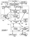
- the biases are transmitted to the GPS processing system 700 of the vehicle 102.
- the GPS processing system 700 uses these biases to eliminate errors in vehicle position estimates.
- the spatial and clock biases are transmitted to the GPS processing system 700 of the vehicle 102.
- the GPS processing system 700 uses these biases to eliminate errors in vehicle position estimates.
- GPS satellites 132-170 in six orbits 174-184 are currently envisioned for the NAVSTAR GPS. They are planned for deployment by 1993. As currently envisioned, the GPS satellites 132-170 will orbit the Earth 172 at an altitude of approximately 14,000 miles and encircle the globe twice a day. Using the C mode of the NAVSTAR GPS, as will be discussed below, it will be possible to determine terrestrial positions within 15 meters in any weather, any time, and most areas of the Earth 172.
- Another method involves satellite position data that is encoded in the electromagnetic signals being transmitted from the orbiting GPS satellites.
- Almanac data relating to the GPS satellite position data of the NAVSTAR GPS is publicly available. Reference to this almanac data in regard to data encoded in the electromagnetic signals allows for an accurate derivation of pseudoranges if the receiver location is known. Pseudoranges computed using the foregoing method are referred to in the context of this document as "estimated" pseudoranges.
- the carrier frequency is modulated using a pseudorandom binary code signal (data bit stream) which is unique to each GPS satellite.
- the pseudorandom binary code signal is used to biphase modulate the carrier frequency. Consequently, the orbiting GPS satellites in the NAVSTAR GPS can be identified when the carrier frequencies are demodulated.
- the foregoing approximate accuracy of the NAVSTAR GPS is affected by (1) the number of GPS satellites transmitting signals to which the Earth receiver is effectively responsive, (2) the variable amplitudes of the received signals, and (3) the magnitude of the cross correlation peaks between the received signals from the different GPS satellites.
- a radio transceiver which functions appropriately in the preferred embodiment as the data radios 620 and 622 is commercially available from Dataradio Ltd. of Montreal, Canada, Model Number DR-48OOBZ.
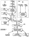
- the GPS intercommunication processor 708 transmits the above information to the GPS processor 710.
- the GPS processor 710 comprises the 68020 microprocessor, which is commercially available from Motorola Inc.
- Figure 8 is a low level flow diagram 800 illustrating the functioning of the software in the GPS processor 710.
- the function of the Kalman filter 802 is to filter out noise associated with the pseudorange data.
- the noise may include, for example, ionospheric, clock, and/or receiver noise.
- the GPS Kalman filter 802 of the host processing system 186 at the base station 188 computes spatial and clock biases which are both transmitted to the vehicle 102 for increasing the accuracy of first position estimates (as discussed in Part II.F.2. of this document). In contrast, the GPS Kalman filter 802 in the vehicle 102 takes into consideration the spatial and clock biases which are received from the base station 188.
- the GPS processor 710 then computes the estimated pseudoranges, the first position estimate, and the vehicle velocity (from Doppler shift) using the above current state and any biases, including the clock biases and the spatial biases. However, the GPS processor 710 discards the computed velocity data when the C/A code, rather than the carrier frequency, is utilized by the GPS receiver 706 to derive the vehicle velocity.
- the rationale for discarding the vehicle velocity is that experimentation has shown that it is not adequately accurate when derived from the C/A code.
- the GPS processor 710 analyzes both the carrier frequency and the C/A code. Unlike data demodulated from the C/A code, data may be retrieved from the carrier frequency by the GPS receiver 706 at approximately 50 Hz (not approximately 2 Hz, as is the case for demodulating C/A code). This increased speed allows the present invention to produce more precise position and velocity determinations with less error.
- the GPS data collection device 718 can be any of numerous common electronic processing and storage devices such as a desktop computer. Any personal computer (PC) manufactured by the International Business Machines corporation (IBM) of Boca Raton, Florida, U.S.A., can be implemented.
- PC personal computer
- IBM International Business Machines corporation
- the VPS main processor 1002 is coupled to the VPS I/O processor 1004.
- the VPS main processor 1002 transmits a signal 1008 to a VPS I/O processor 1004, as shown.
- the signal 1008 comprises the third position estimate.
- the third position estimate is derived from the GPS, IRU, and odometer data noted above, and more specifically, the first and second position estimates of the vehicle 102.
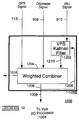
- the weighted combiner 1204 processes the signals and gives a predetermined weighing factor to each data based on the estimated accuracy of data gathering technique used.
- the first position estimate of the GPS signal 716 is weighted heavier than the second position estimate of the IRU signal 910.
- the reason for this weighing scheme is that the first position estimate is inherently more accurate than the second position estimate from the IRU 904.
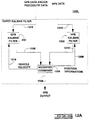
- FIG 12A illustrates a super Kalman filter 1200A of the present invention.
- the super Kalman filter 1200A is a system and method for processing data to increase the accuracy of position estimates of the vehicle 102. Specifically, the super Kalman filter directly increases the accuracy of the first position estimate. Accordingly, the accuracy of the third position estimate is indirectly enhanced.
- the super Kalman filter 1200A comprises software within the architectures of the GPS processing system 700 at Figure 7 and the VPS 1000 at Figure 10. It is envisioned that the super Kalman filter 1200A could be constructed in hardware, for example, as in an integrated circuit, an optical filter, or the like.
- the super Kalman filter of Figure 12 and 12A has the beneficial attributes of both a single Kalman filter and of separate Kalman filters.
- the GPS Kalman filter 710 and the VPS Kalman filter 1202 can continuously exchange data to thereby increase the accuracy of first and second position estimates. Consequently, third position estimates are enhanced.
- a single Kalman filtering system resides between the ultimate output of the third position estimate and the position data being inputted.
- the host processing system 186 at the base station 188 further coordinates the autonomous activities of the vehicle 102 and interfaces the VPS 1000 with human supervisors.
- the present invention improves the accuracy of the position estimates of the vehicle 102 via a number of differential correction techniques. These differential bias techniques are used to enhance the first, second, and third position estimates.
- the host processing system 186 at the base station 188 is responsible for executing these differential techniques and for forwarding the results to the vehicle 102.
- the host processing system 186 comprises the GPS processing system 700, just as the vehicle 102.
- the term "differential" is used because the base station 188 and the vehicle 102 use independent but virtually an identical GPS processing system 700.
- the base station 188 is stationary and its absolute position is known, it serves as a reference point from which to measure electronic errors (noise or interference) and other phenomena inducing errors.
- Figure 13 is a flowchart 1300 of the constellation effects method for improving the accuracy of first position estimates in the preferred embodiment of the present invention.
- the method may be implemented in the GPS processing system 700 at the vehicle 102.
- the method may be implemented in the host processing system 186 at the base station 188. In the latter case, the information determined by the method would subsequently be communicated to the vehicle 102 for appropriate enhancement of first position estimates.
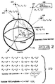
- the following information is inserted into these almanac equations: (1) the parameters identifying the GPS satellites, which are encoded in the GPS data from the GPS satellites, (2) the current time, and (3) the known location of the base station 188.
- the GRAF is used along with the angle of the major access to compute a weighing factor, which will ultimately assist the GPS processing system 700 to compute a more accurate first position estimate as described below.
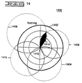
- the GPS Kalman filter 802 in the GPS processing system 700 at the vehicle 102 is modified to accommodate for the shape of the estimated ellipsoid and for the computed northing-easting coordinates of the vehicle 102, as illustrated in Figure 14.
- the foregoing procedure is repeated continuously so as to continuously enhance the estimated position of the center 1412.
- the optimal satellite constellation for the desired vehicle path is determined.
- the optimal constellation will be one that gives the least error perpendicular to the desired vehicle path.
- the original biases are used to update the GPS Kalman filter 802 in the vehicle 102.
- the updating of the GPS Kalman filter 802 results in more accurate first position estimates.
- each GPS satellite 132-170 rise and fall in the sky, the path formed by each GPS satellite 132-170 follows a parabola with respect to tracking pseudoranges on or near the Earth's surface. Therefore, a parabolic function can be derived which represents the path of each GPS satellite in the sky.
- the foregoing describes the essence of the parabolic bias technique, which is performed in the host processing system 186 at the base station 188 in the preferred embodiment. It should be noted, however, that the parabolic bias technique may be performed at the vehicle 102.
- the flowchart 1600 begins at a flowchart block 1602.
- a flowchart block 1604 at a time t(n), actual pseudoranges are determined for each GPS satellite in view of the GPS antenna 702 at the base station 188, using the GPS receiver 706, as described above.
- the actual pseudoranges are incorporated into parabolic best fit models for each GPS satellite.
- one point is added on the parabolic model for each GPS satellite.
- this R 2 value is greater than 0.98 in the preferred embodiment, then the parabolic model is deemed to be accurate enough to estimate the future path of the GPS satellite. If the R 2 value is less than or equal to 0.98, then more points on the parabolic model must be computed. These points are computed by incorporating the pseudorange data which is continually being computed by the GPS receiver 706.
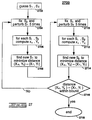
- Figure 17A illustrates a high level flowchart 1700A of a base correlator technique utilized in the present invention to improve the accuracy of the first position estimates of the vehicle 102.
- the technique involves using the known position of a reference point as a way of increasing accuracy.
- the base station 188 serves as the reference point.
- the methodology of flowchart 1700A will be discussed in detail below with specific reference to Figure 6.
- base spatial biases and clock biases (base clock biases) are initially computed by the host processing system 186 at the base station 188 of Figure 6, as indicated in flowchart block 1705.
- the base spatial biases can be any spatial error computation including, but not limited to, the original and parabolic biases discussed previously in this document.
- the parabolic bias is computed by constructing parabolic models for the base actual pseudoranges of each observed GPS satellite and extrapolating values from the parabolic models.
- the parabolic biases are the base actual pseudoranges minus the value extrapolated from the constructed parabolic models and minus the base clock biases (in units of length).
- its GPS receiver 706 computes its own actual pseudoranges (vehicle actual pseudoranges), its own estimated pseudoranges (vehicle estimated pseudoranges), and its own clock biases (vehicle clock biases). From the vehicle actual pseudoranges, its GPS processor 710 subtracts the vehicle estimated pseudoranges, the vehicle clock biases, and the base spatial biases which were sent from the base station 188 in flowchart block 1709. The result is a more accurate calculation of the vehicle spatial bias at the vehicle 102.
- the vehicle spatial bias is then utilized to more accurately modify the first position estimate (FPE) of the vehicle 102, as shown in flowchart block 1717.
- FPE is an estimate of the absolute position (with respect to the Earth 172's center) of the vehicle 102.
- the vehicle 102 next calculates an estimated position (base estimated position; BEP) of the base station 188 using the base actual pseudoranges, base estimated pseudoranges, base spatial biases, and base clock biases, which all were transferred to the vehicle 102 from the base station 188.
- BEP is an absolute position (relative to the Earth 172's surface).
- HBE estimated relative position
- the offset is compared to a preselected threshold.
- each vector component has a corresponding threshold. If all the vector components are not less than their corresponding preselected thresholds, then the flowchart 1700A starts again at flowchart block 1721, as indicated by a feedback arrow 1739. In this case, the positive integer i is increased by one to indicate another iteration and a different FPE(i).
- the present invention will operate in a cyclical, or loop-like, manner until the preselected threshold is achieved or surpassed.
- the present invention can provide for the prediction of satellite availability and unavailability in a systematic manner. It further allows for future planning related to the operation, service, and maintenance of the vehicle 102.
- base clock biases and/or base spatial biases are manipulated so that the estimated base position is within the preselected threshold, as shown at a flowchart block 2114.
- the base clock biases needed to bring the base estimated position within the threshold of acceptability are then sent to the vehicle 102, as indicated at the flowchart block 2116.
- a hauling vehicle may be loaded with ore in any number of ways, by human operated shovels for instance, controlled either directly or by remote control, or by autonomous shovels.
- the hauling vehicle then must traverse an area called the haul segment which may be only a few hundred meters or may be several km's.
- the dump site At the end of the haul segment is the dump site, where the ore is dumped out of the hauling vehicle to be crushed, or otherwise refined, for instance.
- autonomous positioning and navigation may be used to control the hauling vehicle along the haul segment. Autonomously navigated refuelling and maintenance vehicles are also envisioned.
- the VPS 1000 subsystem of the overall AMT system as described above outputs position data that indicates where the vehicle is located, including, for example, a North and an East position.
- the navigator may be required to then decide if action is required to avoid the obstacle. If action is required, the navigator decides how to avoid the obstacle. And after avoiding the obstacle, the navigator decides how to get the vehicle back onto a path towards its destination.
- portions of the VPS and navigator may be located at the base station.
- Another factor in determining the particular location of elements of the system of the present invention is the time-criticality of autonomous navigation.
- the navigation system must continually check its absolute and relative locations to avoid unacceptable inaccuracies in following a route.
- the required frequency of checking location increases with the speed of the vehicle, and communication speed may become a limiting factor even at a relatively moderate vehicle speed.
- path tracking takes, as input, the detailed path generated and controls the vehicle 102 to follow the path as precisely as possible. It is not enough to simply follow a pre-made list of steering commands because failure to achieve the required steering motions exactly, results in steady state offset errors. The errors accumulate in the long run.
- Global position feedback 432 may be used to compensate for less than ideal actuators. Methods have been developed for the present invention which deviate from traditional vehicle control schemes in which a time history of position (a trajectory) is implicit in the plan specified to the vehicle 102.
- Postures are used to model parts of a route, paths and nodes for instance. Postures may consist of position, heading, curvature, maximum velocity, and other information for a given point on the path.
- a "path” is a sequence of contiguous postures.
- path planning Determining which postures are required to define a path segment by analytical, experimental or a combination of both, is called "path planning" in accordance with the present invention.
- path planning a sequence of contiguous routes, as mentioned above, is referred to as a "cycle,” and a vehicle 102's work goals determine its "cycle.”
- B-splines provide continuous curvature and therefore enhance tracking performances.
- B- splines are free form curves, a route may be defined by a single B-spline curve. By using free form curves, a more robust method (semi-automatic) for fitting routes to data collected by driving the vehicle over the routes is produced by the present invention.
- the path segments are stored in a memory called the TARGA 5302 as a set of arcs, lines, and postures.
- an analytical generator function generates paths using these arcs, lines and postures.
- B-splines are used as a mathematical representation of a route, as mentioned above.
- clothoid curves are used in generating path segments. These are discussed below.
- part of the navigation problem addressed and solved by the present invention is really two sub-problems: path planning and path generation. These are solved separately by the present invention.
- the challenge of path generation is to produce from the objective points (of path planning), a continuous, collision-free path 3312, smooth enough to be followed easily by the autonomous vehicle 102.
- a simple scheme is to decompose a path 3312 into straight lines and circular curves.
- the path 3312 is then converted into a sequence of explicit directives provided to the vehicle 102 actuators to keep the vehicle on the desired path 3312. It should be noted that there is a distinct trade-off between simplicity of representation of such plans and the ease with which they can be executed.
- the ability of an autonomous vehicle 102 to track a specified path 3312 is dependant on the characteristics of the path. Continuity of curvature and the rate of change of curvature (sharpness) of the generated path 3312 are of particular importance since these parameters dictate steering motions required of a vehicle 102 for it to stay on the desired path 3312. Discontinuities in curvature are impossible to follow since they require an infinite acceleration.
- the extent to which the sharpness of a path is linear is the extent to which steering motions are likely to keep the vehicle on the desired path 3312, since linear sharpness of a path equates to approximately constant velocity of steering.
- One method used by the present invention is to compose paths as a sequence of straight lines and circular arcs. This method suffers from discontinuities in curvature where arcs meet.
- Another method of the present invention is to use polynomial splines to fit paths between objective points. Splines assure continuity in curvature, but do not make any guarantees of linearity in sharpness.
- the method of the present invention generates explicit paths that pass through a sequence of objective points.
- a derivative method of the present invention replans parts of the path dynamically in case the tracking error becomes large or the desired path is changed.
- Any path can be parameterized as a function of path length (s) by position coordinates (x(s), y(s)) 3304. That is, position coordinates x and y can be written as explicit functions of the path length s.
- the quadruple of these parameters, p (x,y,0,c) , is a posture 3314 that describes the state of an autonomous vehicle 102 at any point in time.
- a clothoid curve segment 2002 is shown in Figure 26.
- Kanayama et al. entitled, "Trajectory Generation for Mobile Robots", Robotics Research: The Third International Symposium, ISIR , Goutiri, France, 1986, makes use of paired clothoid curves with straight line transitions between postures.
- the constraint of straight line transitions is due to the integrals in Eqs. (7) and (8) which do not have closed form solutions.
- 0 i O ; only a straight forward approximation of o s sin(k ⁇ 2 )d ⁇ is left.
- Clothoid replanning is done either to acquire the path initially, or to guide the vehicle 102 back to the desired path 3312 through normal navigation according to the present invention.
- the present method accrues additional advantages in that preprocessing of the objective points is not necessary as with arcs and zero curvature clothoids. Further, the geometry of the paths generated always sweeps outside the acute angles formed by straight line connection of the way points. These are especially useful for interpolating around obstacles that are commonly on the inside of angles.
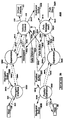
- Figures 29 shows an example of B-spline curves.
- An application on an APOLLO Computer (now HEWLETT-PACKARD of Palo Alto, California) work station (a graphics display system, not shown) was developed to graphically fit route data to the stored driven date and to further define routes (that is, speeds, sequences, starting point, traversal direction). Any graphics work stations equivalent to the APOLLO could be used.
- routes in the present invention may he predefined, or they may be generated dynamically.
- the following method is used for route definition.
- the vps_posture task 5324 determines the position, along the route which is closest to the vehicle 102's present position 2812. The search for the closest position 284 on the route proceeds as follows:
- the vps-posture task 5324 then informs the executive 5316 that it is ready for tracking.
- the safety margin 3006 is depleted.
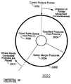
- the vps_posture task 5324 When the safety margin is below a specified amount, the vps_posture task 5324 generates another safety margin 3006 of postures and appends them to the current buffer 3000.
- the vps_posture task 5324 depletes the posture buffer 3000 by monitoring the current position 2812 of the vehicle 102 and moving a pointer 3002 in the buffer 3000 to the nearest posture.
- the posture buffer 3000 is constructed as a ring which is traversed in the clockwise direction (see Figure 30, Posture Ring Buffer). That is, postures are placed in the ring such that the direction of vehicle travel corresponds to a clockwise traversal of the posture ring buffer 3000.
- a path is as a series or sequence of contiguous "postures.”
- a posture includes the speed and steering angle required to be on track.
- a posture may include latitude, longitude, heading, curvature (1/turning radius), maximum velocity and distance to next posture information.
- the tracking method of the present invention requires certain information about the route it is tracking.
- the information is contained in a packet called a "posture" 3314.
- a single posture 3314 may contain position (that is, north and east coordinates), heading, and curvature data, for a specified location on the route. Therefore, a way of producing posture data from the route specification is required in accordance with the present invention.
- the task which produces the postures reads the current position of the vehicle 102, finds the nearest point on the route to the current position, then generates a specified number of postures ahead of the vehicle 102.
- the number of postures generated is dependent on the maximum stopping distance of the vehicle 102. That is, there should always be enough postures in the buffer 3000 to guide the vehicle 102 to a stopping point.
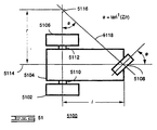
- path tracking is determining the autonomous vehicle commands (speed, steer angle) required to follow a given path. Given a pre-specified steering angle, driven wheel velocity values and error components, the command steering and driving inputs are computed in the present invention.
- the path to be tracked is specified in Cartesian coordinates. If the control scheme consists of only a servo-control to reference steering commands, vehicle position and heading errors accumulate. Position and heading result from integrating the whole history of steering and driving. Thus, it is necessary to feedback vehicle position 3304 and heading 3318 in Cartesian space.
- One of the challenges of vehicle autonomy is to determine the steering inputs required to track a specified path.
- the desired path and the desired speed along the path can be tracked separately, reducing the problem to one of controlling the steering.
- a path for this discussion, being a geometric curve independent of time in contrast to a trajectory, which is a time history of positions.
- the desired posture at the end of the next time interval (P d,k+2 ) 3218 is computed in a referenced steering angle between ( P a,k+1 ) 3216 and (P d,k+2 ) 3218 are determined.
- the images In order to process all the available data, the images must be processed at the frame rate of the scanner 3804. For this reason, most of the computations in the obstacle extraction method are done in the image plane 3901. By projecting the path into the image, a large portion of the image can be ignored, and many needless computations avoided.
- the obstacle locations are obtained from the laser range scanner 3804 or 404.
- the range data generated by the scanner 3804 or 404 are processed to produce a list off polygonal faces, modeling the visible portions of the obstacle 4002 from the vehicle position.
- the frequency at which the sub-goal selection method can be executed depends on the rate at which the scanner 3804 or 404 can collect data.
- the achievable vehicle speed in turn, depends on this frequency of execution.
- the steering decision method For the steering decision method, a higher sampling rate is desirable in order to produce a smooth path. Therefore, the steering decision method is executed more frequently than the sub-goal method.
- the basic flow of the sub-goal method is the following:
- Sub-goal Method First (step 1 above), the initial-subgoal, subgoal, and free-space generated from the previous iteration is saved. This assures that when the newly generated subgoal is not safe, the old subgoal can continue to be pursued.
- step 2 when the final goal is visible, attempt to generate a direct goal which is not associated with any obstacles 4002.
- the final goal is visible in the local map, it does not necessarily mean that no obstacle is blocking the final goal because obstacles outside the scanner range (both distance and angular wise) will not be represented in the local map. Therefore, when generating a direct goal, ensure that the goal is located in the cone area which is covered by the scanner 3804 or 404 to avoid placing a subgoal on or behind an obstacle 4002 that is not in the local map.
- the next step handles the situation where the final goal is blocked by an obstacle 4002 in the local map.
- the obstacle 4002 that blocks the line of sight to the final goal is first determined.
- both edges of the obstacle are in the range of the scanner 3804 or 404, we may choose to go around the edge which gives the minimum sum of the distances from the vehicle 102 to edge and from the edge to the final distance. If only one edge of the obstacle 4002 is in the range, choose that edge to go around. If none of the edges is visible, always arbitrarily choose the left edged to go around. Once the edge to go around is determined, place the initial subgoal away from the edge at a distance that is proportional to the vehicle size.
- the resulting subgoal may be blocked by other obstacles 4002. This calls for the recursive generation of subgoal on the obstacle, which blocks the line of sight to the subgoals just generated. This recursive process continues until a subgoal visible to the vehicle 102 is generated. Each subgoal so generated is checked for viability. By viability it is meant that the subgoal does not lead the vehicle 102 towards a gap between two obstacles 4002 which is too small for the vehicle to pass through. When such a condition is detected, the vehicle 102 will stop.
- step 2 above The direct subgoal generated in the second step (step 2 above) could possibly be obscured from the vehicle 102. If such is indeed the case, the old subgoals from the previous iteration is restored and used next (step 4 above).
- step 5 In the final step (step 5 above), generate the free-space 4010 for the visible subgoal, which is a triangular region that contains no obstacles. Once the free-space 4010 is generated, the safeness of the subgoal and free-space 4010 can be determined. When the new subgoal and free-space 4010 is not safe, the old subgoal and free-space is again retained. Otherwise, the new subgoal and free-space is used.
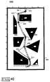
- the present invention includes a method, as shown diagrammatically in Figure 40, whereby a safe path around a detected object 4002 will be plotted and navigated so that the vehicle 102 will reacquire the reference path after avoiding the object 4002.
- the beam 3810 from the range finder 404 is reflected by a rotating mirror 4222 giving the range finder 404 a 360° view of the world.
- Mirror rotation is accomplished through a motor 4206.
- the motor speed is controlled via a terminal 4210, which communicates with a motor amplifier/controller 4220 through a standard RS232C serial link 4224. Synchronization between laser firings and mirror angular position is done with an encoder.
- Distance data on a line 4226 from the laser range finder 404 is taken by an interface circuit 4228, which transmits the data differentially to a buffer circuit 4214. Individual pieces of data are collected by the buffer circuit 4214 until the mirror 4222 makes one full revolution. This set of data comprises one scan. When a scan is complete, the buffer circuit 4214 signals a processor 4212, whereupon data for the entire scan is transferred to the processor 4212 for processing.
- the interface circuit 4228 has three functions.
- the third function of the circuit 4228 is to convert signals between single ended and differential form. TTL signals from the laser unit 4204 are differentially transmitted to the buffer circuit 4214, and differentially transmitted signals from the buffer circuit 4214 are converted to TTL levels. This prevents noise contamination along the cable 4226 connecting the two circuits.
- the function of the buffer circuit 4214 is to synchronize laser 404 firings with the angular position of the mirror 4222, to collect data for one complete scan, and to transmit the scan to computer 4214 for processing.
- the angular position of the mirror 4222 can be determined through signals sent by the encoder 4208.
- the buffer circuit 4214 uses two signals from the encoder 4208: the Z and A channels.
- the Z channel is the encoder index; it gets asserted once per revolution of the encoder 4208, and is used to signal the beginning of the scan area.
- One additional signal is needed to fully synchronize the scan field with the encoder signals.
- Two revolutions of the encoder 4208 rotates the mirror 4222 once. This translates to 2Z channel pluses and 2000 A channel pulses per revolution of the mirror 4222, and the inability to differentiate the beginning of the first half of the scan with the beginning of the second half.
- the DB (dead band) signal generated by the interface circuit 4222 is used.
- the DB signal used to disable the laser 4204 from firing in the back half of the scan, allows the differentiation of the front and back halves of the scan.
- the Z and DB signal together signal the beginning of the scan area.
- the interrupt is acknowledged.
- STR data strobe
- IBF input buffer full
- data is put on the data bus 4230 and may be ready by the computer 4212.
- Data is valid on the bus 4230 until IBF is asserted, at which time STR is de-asserted and the data removed from the bus 4230.
- the processor 4212 detects the de-assertion of STR, it de-asserts IBF. This causes STR to be asserted for the next piece of data, repeating the cycle.
- Scan data is collected and stored in two memory banks 4214. This avoids shared memory and synchronization problems between scan storage and scan transmission. Data for a new scan is stored in one bank, while the previous scan is being transmitted from the other bank.
- the bus 4314 is a data collision detection, packet passing system.
- Each of these functional blocks have separate microprocessors, for instance of the Motorola 68000 16 bit series. Each of these microprocessors talks to and listens to the others over the bus 4314.
- the ready mode 4404 brings the vehicle 102 to a stop in a known state. This is because it would be difficult to make a smooth transition, from, for instance, auto mode 4408 to tele mode 4406 while the vehicle 102 was moving.
- the tele control panel joy-stick 4502, 4504 would have to be in just the right position when control was switched.
- the navigator 406 must initialize. For example, it must determine where it is with respect to a route before taking control, which takes some finite time, during which the vehicle 102 might otherwise drive off uncontrolled.
- Tele control mode 4406 also referred to as tele-operation, remote control or radio control mode, provides a way of controlling the vehicle 102 from a remote location while the vehicle 102 is kept in view.
- This control mode may be implemented to be invoked whenever a human operator activates any of the manual controls.
- the simple action of stepping on the brakes 4708, moving the shift lever from some predetermined, autonomous mode position, or grasping the steering wheel 4910, for example, would immediately signal the control system that manual control mode 4402 is desired and the system would immediately go to the manual mode.
- the autonomous mode 4408 is entered into from ready mode 4404.
- the vehicle 102 is under the control of the autonomous navigation system.
- the vehicle control system receives messages from the navigator 406 as discussed above, through the vehicle manager 4302.
- the vehicle manager 4302 is, as discussed, basically the communications and command hub for the rest of the controllers.
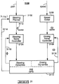
- the speed control subsystem 4302 may be organized to contain a speed command analyzer, closed loop controls 4800 for the engine 4614, transmission and brakes 4700, 5000, a real time simulation model of the speed control system, and a monitor 4310 that is tied to an independent vehicle shutdown system 4312. It is designed to be placed in parallel to the production system on the vehicle 102.
- the speed control functional block 4304 takes care off three basic functions. It controls the governor on the engine 4614. It controls the brake system 4606. And it controls the transmission 4610 via the production transmission control block 4616.
- the production transmission control block 4616 is interfaced with the speed control block 4304 in a parallel retro-fit of the autonomous system onto the production system as shown in Figure 48.
- the production transmission control block 4616 is a microprocessor based system which primarily monitors speed and shifts gears accordingly.
- the autonomous system speed control block 4304 feeds the transmission control block 4616 the maximum gear desired. For instance, if the vehicle 102 is to go 15 mph, the maximum gear might be third gear.
- the production transmission control block 4616 will control all the shifting necessary to get to that gear appropriately.
- the governor 4626 ( Figure 46) controls the amount of fuel delivered to the engine 4616. Thus, it controls engine speed.
- the autonomous system is capable of being retro-fitted in parallel with the production governor control system, in a similar fashion as described with respect to the transmission system.
- a governor 4626 controls engine speed 4222, which in turn controls vehicle speed 4624.
- the engine power is transferred to the drive wheels through the drive train 4600 which is comprised of:
- the system also provides for sensing the pneumatic pressure which is a key part for actuating some of the key systems. If this pressure falls below some preset threshold, it is assumed that there is a problem and the vehicle control system reverts to manual control 4402 and the vehicle 102 is stopped.
- Control of vehicle steering is also required for the vehicle to operate autonomously.
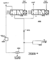
- the system which performs this function is shown in Figure 49.
- the system consists of a Rexroth proportional hydraulic valve 4912 which can be actuated electronically to provide flow to hydraulic cylinders 4914 and 4916 attached to the vehicle steering linkage.
- the system also comprises a manually operable hand-metering unit, or HMU, 4918, which is in parallel to the electronically controlled system.
- the manual system can override the electronic system, if required, as a safety measure.
- the system provides a switch 4920 on the HMU to detect when the manual steering wheel 4910 is different from the centered position. When not centered, the autonomous system assumes that the system is being operated manually 4402 and disables autonomous control of the vehicle 102.
- the steering control functional block 4306 is responsible for controlling the steer angle of the vehicle's wheels. It sends out commands to a valve 4912 to control the steer angle and receives information from a resolver (not shown) mounted on the tie rod system, so that it knows what the actual wheel angle is.
- the navigator 406 constantly monitors the vehicle 102 to determine how far the vehicle 102 is from the desired path 3312. (The vehicle 102 is always off the desired path 3812 to some extent, and the system is constantly correcting.) If the vehicle 102 is more than a certain distance, for example several meters, from the desired path 3312, the navigator 406 stops the vehicle as a safety precaution.
- a switch 4920 on the HMU 4918 detects off-center position of the steering wheel 4910 as an indication to change to manual control of steering. An operator riding in the cab can merely turn the steering wheel 4910 to disable autonomous steering control 4408.
- the desired path 3312 must contain the curvature of the path to be followed.
- the curvature is the inverse of the instantaneous radius of curvature at the point of the curve.
- a posture 3314 is desired as the quadruple of parameters--position 3320, heading 3318, and curvature 3316 (x, y, 0, c), then it is required that the path 3812 be posture-continuous.
- the extent to which steering motions are likely to keep the vehicle 102 on the desired path 3312 correlates with the linearity of sharpness of the path, since linear curvature along a path means linear steering velocity while moving along the path.
- Clothoid curves 2602 have the "good" property that their curvature varies linearly with distance along the curve. Paths composed of (a) arcs and straight lines or (b) clothoid segments have been developed.
- a path that has discontinuities in curvature results in larger steady state tracking errors. This is particularly the case when the actuators are slow.
- the path representation must contain sufficient information to calculate the steer angle 3112 (See Figure 31) needed to drive the desired path 3312, that is, it must consist of at least the position, heading, curvature and speed.
- a position on the desired path 3312 has been defined as a posture 3314, and the structure of a posture in the present invention is given by:
- the position information 3322 is obtained from the VPS 1000 and is, for example, 71 bytes of data.
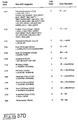
- the structure of the information used to track the desired path 3312 is a subset of the 71 byte VPS output and is given by the VPS short definition shown below.
- the method of the present invention used to calculate Cerror is a quintic method.
- the quintic is a fifth degree polynomial in an error space that defines a smooth path back to the desired path 3312.
- the degree of the polynomial is defined by the needed data, that is, Cerror and the known end constraints.
- the monitor/auxiliary functional block(s) 4308 and 4310 take care of some miscellaneous functions not performed by the other blocks of the vehicle control system. For instance, start or kill the engine 4616, honk the horn, raise or lower the bed, setting the parking brake on or off, turning the lights on or off, are some of its functions.
- the monitor block 4310 also checks the commands that are being sent by or to the other functional blocks on the bus 4314 to see if they are valid. If error is detected, it will signal the shutdown circuits block 4312 and the system will shutdown as discussed below.
- the safety system including shutdown circuits 4312, (see Figures 43 and 52) operates to stop the vehicle 102 on detection of a variety of error conditions by setting the parking brake on. This results in the vehicle 102 coming to a safe stop in the shortest distance possible.
- the parking brake is designed to be normally “set” or “on,” and the electronic circuits operate to release it, upon a failure of the electronic controlling system(s) the power 5216 is turned off to the actuators 5006, so that there is no power to actuate valves, and the parking brake returns to its normal position, called "set.”
- the safety system shutdown circuit 4312 shown in Figure 43 connected to receive the outputs of the other vehicle control system functional blocks is shown in more detail in Figure 52.
- a feature of the vehicle control system 4312 design is that all functional blocks are capable of detecting errors in the output of the others on the serial bus 4314. So if one of them senses that another is not functioning correctly, it can send a signal to the shutdown circuits 4312 to shut the system down.
- the speed and steering blocks each look at their received commands (received via the vehicle manager 4302) to make sure they are valid. They also make sure that what they are told to execute, that is, what they are requested to command, is within predetermined bounds. If not, they will act to shut the system down.
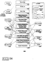
- the console 5312 and the console-parser 5314 are shown just below the "main" task 5316 in the task diagram Figure 53. These tasks were developed as a debugging tool during the development of the system. They display and manipulate navigator 406 states according to user input from a terminal 5302. The console_parser task 5314 also is used to set tracker parameters.
- This task 5320 is shown in the upper left-hand corner of the task diagram Figure 53. It is part of the host-navigator interface 5330. Messages from the host processing system 186 are received and decoded by this task 5320. Then, depending on the message, the message is either communicated to the "main" task 5316, or to another task. This other task would then formulate an appropriate response from the navigator 406 to the host processing system 186.
- This task 5318 shown just above and to the left of the "main" task 5316, formulates messages from the navigator 406 to the host processing system 186 and communicates them to the host processing system 186.
- This task 5322 is shown at the left side of the task diagram Figure 53.
- the vps_position task 5322 reads the (20 Hz) output from the VPS 1000. The data is checked for correctness (for example, "checksum”) and if correct, it is put into a global memory structure 5400, the position buffer (VPS_POSITION_QUEUE) 5332. The task sends a message to the "main" 5316 whenever a position fault occurs.
- the task 5306 reads the current position 5332 and posture buffers 5334. Based on the information read, task 5306 calculates steer and speed corrections 420. It sends them to the vehicle 102, thereby controlling the vehicle's course.
- the navigator 406 has a global memory structure 5400 which the various tasks read/write. This memory structure 5400 is illustrated in Figure 54.
- the memory 5400 is depicted in the center section of Figure 54 as a stack of boxes. Unprotected memory is depicted as a single box in the stack of boxes. Semaphore protected memory is depicted as a box within a box in the stack.
- An arrow points in the direction of data transfer between tasks and memory. Therefore, a write to memory from a task is shown as a line with an arrow pointing towards the memory in question from the task. Likewise, a read from memory by a task is depicted by a line with an arrow pointing towards the task in question from the memory. Where two-way data transfer between task and memory exists, a line with an arrow at both ends is shown.
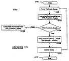
- Figures 55 and 56A-56D are flow charts of the navigator main or executive task 5316.
- FIG 55 which is the executive flowchart, it shows of five blocks: block 5502 which is the Start block; block 5504 which is the initialize navigator; block 5506, which is the Pend on Exec Queue; block 5506, which is the executive decisions; and block 5510, which is the act on state.
- Flowchart Figure 55 describes how the executive task 5316 executes its functions beginning at power up (switching on electrical power) of the navigator 406.
- the executive task 5316 (or Executive) begins at the start block 5502 and proceeds immediately to initialize navigator 5504, where the executive 5316 puts the navigator 406 in a known initial state.
- the executive then proceeds to the Pend on exec queue 5506 and waits for a message from a number of sources to arrive in its message queue 5328.
- a typical message could be a query for information from the host processing system 186.
- the executive 5316 Upon receipt of a message in the Exec Queue 5328, the executive 5316 proceeds to the executive decisions block 5508. In this block, the executive 5316 sets a series of status flags in a known manner. These flags put the navigator 406 in a known state, particular to the message received.
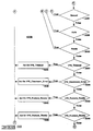
- Figures 56A-56D show the flow of the "executive decisions" block 5508 of the general structure diagram Figure 55.
- Figure 56A diagrams the organization of Figures 56A-56D.
- Figures 56A-56D describe in detail the procedure which the executive 5316 uses to respond to various messages.
- the executive 5316 is directed to block 5680, where the host processing system 186 is informed of the problem. The executive 5316 then returns to the Exec Queue 5506 to respond to the next message in the queue.
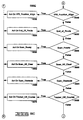
- Figures 57A through 57R show the specific procedures which the executive 5316 uses to respond to a particular message.
- Figure 57A details how the executive 5316 responds to a 'NEW-ROUTE_DIRECTIVE' message.
- the executive 5316 then proceeds to a flowchart block 5702 to determine what the message is: in this case, 'NEW_ROUTE_DIRECTIVE'. If the message is 'NEW_ROUTE_DIRECTIVE', the executive 5316 then proceeds to a flowchart block 5705 to respond to the message. Otherwise, it proceeds on to a flowchart block 5704 to determine if it is valid (one of the other possible messages) or invalid.
- the executive 5316 follows the process described in Figure 57A to respond to the message. This process is depicted by blocks 5706 through 5714. In this procedure (and in responses to other directives), the executive 5316 checks the states of different tasks within the navigator 406 and reacts to these states in a known, predetermined manner.
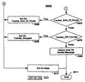
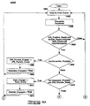
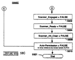
- FIGS 58A-58C illustrate the flow of the "act on state” block 5510.
- Figure 58 shows the interrelationship of Figures 58A-58C, where each of these three figures depict a portion of the Act On State block 5510.
- the executive 5316 then proceeds to send messages to the appropriate tasks or entities which must be informed of changes to the navigator 406 system as a result of the Exec message.
- the executive task 5316 when the executive task 5316 leaves the executive decisions 5508, and first enters the act on state block 5510, it checks to see that the status is set such that the vehicle is ready for autonomous mode (for example - VPS is ready, vehicle is communicating properly, a proper route has been commanded, and the vehicle is ready for auto mode). See block 5802. If one or more of these conditions is not met, then the Exec returns to wait for another valid message. If all of these conditions are met, then the executive 5316 checks to see that the path generator 5804 is operating. If so, then the executive 5316 proceeds to start the other systems required for autonomous operation.
- the status for example - VPS is ready, vehicle is communicating properly, a proper route has been commanded, and the vehicle is ready for auto mode. See block 5802. If one or more of these conditions is not met, then the Exec returns to wait for another valid message. If all of these conditions are met, then the executive 5316 checks to see that the path generator 5804 is operating. If so, then the executive 5316
- the executive 5316 task sends the message 'VPS_POSTURE_ENGAGE' to the Vps Posture Queue 5334, in order to start the path generator.
- the executive task will then return to the Pend on Exec Queue 5506, to wait for another directive so that proper operation of the vehicle 102 is ensured.
Landscapes
- Engineering & Computer Science (AREA)
- Radar, Positioning & Navigation (AREA)
- Remote Sensing (AREA)
- Physics & Mathematics (AREA)
- General Physics & Mathematics (AREA)
- Automation & Control Theory (AREA)
- Computer Networks & Wireless Communication (AREA)
- Aviation & Aerospace Engineering (AREA)
- Transportation (AREA)
- Mechanical Engineering (AREA)
- Combustion & Propulsion (AREA)
- Chemical & Material Sciences (AREA)
- Human Computer Interaction (AREA)
- Manufacturing & Machinery (AREA)
- Position Fixing By Use Of Radio Waves (AREA)
- Navigation (AREA)
- Control Of Position, Course, Altitude, Or Attitude Of Moving Bodies (AREA)
- Instructional Devices (AREA)
- Optical Radar Systems And Details Thereof (AREA)
Applications Claiming Priority (3)
| Application Number | Priority Date | Filing Date | Title |
|---|---|---|---|
| PCT/US1989/005580 WO1991009375A1 (en) | 1989-12-11 | 1989-12-11 | Integrated vehicle positioning and navigation system, apparatus and method |
| WOPCT/US89/05580 | 1989-12-11 | ||
| EP95110798A EP0679974B1 (de) | 1989-12-11 | 1990-12-10 | Integriertes Fahrzeugpositionier- und -navigationssystem; dessen Vorrichtung und Verfahren |
Related Parent Applications (2)
| Application Number | Title | Priority Date | Filing Date |
|---|---|---|---|
| EP91902277.2 Division | 1991-07-12 | ||
| EP95110798.6 Division | 1995-07-11 |
Publications (2)
| Publication Number | Publication Date |
|---|---|
| EP0936521A2 true EP0936521A2 (de) | 1999-08-18 |
| EP0936521A3 EP0936521A3 (de) | 1999-08-25 |
Family
ID=22215414
Family Applications (16)
| Application Number | Title | Priority Date | Filing Date |
|---|---|---|---|
| EP99106275A Withdrawn EP0936521A3 (de) | 1989-12-11 | 1990-12-10 | Integriertes Fahrzeugpositionier- und -navigationssystem, dessen Vorrichtung und Verfahren |
| EP95110797A Expired - Lifetime EP0679904B1 (de) | 1989-12-11 | 1990-12-10 | Integriertes Fahrzeugpositionier- und -navigationssystem; dessen Vorrichtung und Verfahren |
| EP00100132A Expired - Lifetime EP0996047B1 (de) | 1989-12-11 | 1990-12-10 | Integriertes Fahrzeugpositionier- und -navigationssystem, dessen Vorrichtung und Verfahren |
| EP99106272A Expired - Lifetime EP0936518B1 (de) | 1989-12-11 | 1990-12-10 | Integriertes Fahrzeugpositionier- und -navigationssystem, dessen Vorrichtung und Verfahren |
| EP94103866A Expired - Lifetime EP0604404B1 (de) | 1989-12-11 | 1990-12-10 | Integriertes Fahrzeugpositionier- und -Navigationssystem, dessen Vorrichtung und Verfahren |
| EP91902277A Expired - Lifetime EP0507845B1 (de) | 1989-12-11 | 1990-12-10 | Integriertes fahrzeugpositionier- und -navigationssystem dessen vorrichtung und verfahren |
| EP95110799A Expired - Lifetime EP0679976B1 (de) | 1989-12-11 | 1990-12-10 | Integriertes Fahrzeugpositionier- und -navigationssystem; dessen Vorrichtung und Verfahren |
| EP99106274A Expired - Lifetime EP0936520B1 (de) | 1989-12-11 | 1990-12-10 | Integriertes Fahrzeugpositionier- und -navigationssystem, dessen Vorrichtung und Verfahren |
| EP95110798A Expired - Lifetime EP0679974B1 (de) | 1989-12-11 | 1990-12-10 | Integriertes Fahrzeugpositionier- und -navigationssystem; dessen Vorrichtung und Verfahren |
| EP94103865A Withdrawn EP0608005A1 (de) | 1989-12-11 | 1990-12-10 | Integriertes Fahrzeugpositioneer- und -navigationssystem, Vorrichtung dafur und Verfahren |
| EP99106271A Expired - Lifetime EP0936517B1 (de) | 1989-12-11 | 1990-12-10 | Integriertes Fahrzeugpositionier- und -navigationssystem, dessen Vorrichtung und Verfahren |
| EP95110796A Expired - Lifetime EP0679973B1 (de) | 1989-12-11 | 1990-12-10 | Integriertes Fahrzeugpositionier- und -navigationssystem; dessen Vorrichtung und Verfahren |
| EP99106189A Expired - Lifetime EP0936516B1 (de) | 1989-12-11 | 1990-12-10 | Integriertes Fahrzeugpositionier- und -navigationssystem, dessen Vorrichtung und Verfahren |
| EP99106273A Expired - Lifetime EP0936519B1 (de) | 1989-12-11 | 1990-12-10 | Integriertes Fahrzeugpositionier- und -navigationssystem, dessen Vorrichtung und Verfahren |
| EP95110794A Expired - Lifetime EP0679903B1 (de) | 1989-12-11 | 1990-12-10 | Integriertes Fahrzeugpositionier- und -navigationssystem; dessen Vorrichtung und Verfahren |
| EP95110795A Withdrawn EP0679975A2 (de) | 1989-12-11 | 1990-12-10 | Integriertes Fahrzeugpositionier- und -navigationssystem; dessen Vorrichtung und Verfahren |
Family Applications After (15)
| Application Number | Title | Priority Date | Filing Date |
|---|---|---|---|
| EP95110797A Expired - Lifetime EP0679904B1 (de) | 1989-12-11 | 1990-12-10 | Integriertes Fahrzeugpositionier- und -navigationssystem; dessen Vorrichtung und Verfahren |
| EP00100132A Expired - Lifetime EP0996047B1 (de) | 1989-12-11 | 1990-12-10 | Integriertes Fahrzeugpositionier- und -navigationssystem, dessen Vorrichtung und Verfahren |
| EP99106272A Expired - Lifetime EP0936518B1 (de) | 1989-12-11 | 1990-12-10 | Integriertes Fahrzeugpositionier- und -navigationssystem, dessen Vorrichtung und Verfahren |
| EP94103866A Expired - Lifetime EP0604404B1 (de) | 1989-12-11 | 1990-12-10 | Integriertes Fahrzeugpositionier- und -Navigationssystem, dessen Vorrichtung und Verfahren |
| EP91902277A Expired - Lifetime EP0507845B1 (de) | 1989-12-11 | 1990-12-10 | Integriertes fahrzeugpositionier- und -navigationssystem dessen vorrichtung und verfahren |
| EP95110799A Expired - Lifetime EP0679976B1 (de) | 1989-12-11 | 1990-12-10 | Integriertes Fahrzeugpositionier- und -navigationssystem; dessen Vorrichtung und Verfahren |
| EP99106274A Expired - Lifetime EP0936520B1 (de) | 1989-12-11 | 1990-12-10 | Integriertes Fahrzeugpositionier- und -navigationssystem, dessen Vorrichtung und Verfahren |
| EP95110798A Expired - Lifetime EP0679974B1 (de) | 1989-12-11 | 1990-12-10 | Integriertes Fahrzeugpositionier- und -navigationssystem; dessen Vorrichtung und Verfahren |
| EP94103865A Withdrawn EP0608005A1 (de) | 1989-12-11 | 1990-12-10 | Integriertes Fahrzeugpositioneer- und -navigationssystem, Vorrichtung dafur und Verfahren |
| EP99106271A Expired - Lifetime EP0936517B1 (de) | 1989-12-11 | 1990-12-10 | Integriertes Fahrzeugpositionier- und -navigationssystem, dessen Vorrichtung und Verfahren |
| EP95110796A Expired - Lifetime EP0679973B1 (de) | 1989-12-11 | 1990-12-10 | Integriertes Fahrzeugpositionier- und -navigationssystem; dessen Vorrichtung und Verfahren |
| EP99106189A Expired - Lifetime EP0936516B1 (de) | 1989-12-11 | 1990-12-10 | Integriertes Fahrzeugpositionier- und -navigationssystem, dessen Vorrichtung und Verfahren |
| EP99106273A Expired - Lifetime EP0936519B1 (de) | 1989-12-11 | 1990-12-10 | Integriertes Fahrzeugpositionier- und -navigationssystem, dessen Vorrichtung und Verfahren |
| EP95110794A Expired - Lifetime EP0679903B1 (de) | 1989-12-11 | 1990-12-10 | Integriertes Fahrzeugpositionier- und -navigationssystem; dessen Vorrichtung und Verfahren |
| EP95110795A Withdrawn EP0679975A2 (de) | 1989-12-11 | 1990-12-10 | Integriertes Fahrzeugpositionier- und -navigationssystem; dessen Vorrichtung und Verfahren |
Country Status (6)
| Country | Link |
|---|---|
| EP (16) | EP0936521A3 (de) |
| JP (6) | JP3336005B2 (de) |
| AU (2) | AU642638B2 (de) |
| CA (1) | CA2071831A1 (de) |
| DE (13) | DE69033979T2 (de) |
| WO (2) | WO1991009375A1 (de) |
Cited By (5)
| Publication number | Priority date | Publication date | Assignee | Title |
|---|---|---|---|---|
| WO2003040752A1 (en) * | 2001-11-06 | 2003-05-15 | Chang-Don Kee | Pseudolite-based precise positioning system with synchronised pseudolites |
| CN102750833A (zh) * | 2011-04-18 | 2012-10-24 | 约瑟夫福格勒公司 | 用于控制施工场地车辆的系统 |
| EP3967976A1 (de) * | 2020-09-11 | 2022-03-16 | STMicroelectronics (Grand Ouest) SAS | Verfahren zur bewegungsschätzung in einem fahrzeug, entsprechende vorrichtung und computerprogrammprodukt |
| FR3123620A1 (fr) * | 2021-06-08 | 2022-12-09 | Psa Automobiles Sa | Procédé et système pour déterminer des données caractérisant l’évolution du rayon de courbure de la trajectoire d’un véhicule automobile au cours d’un trajet |
| US12545265B2 (en) | 2020-09-11 | 2026-02-10 | Stmicroelectronics S.R.L. | Method for motion estimation in a vehicle, corresponding device and computer program product |
Families Citing this family (238)
| Publication number | Priority date | Publication date | Assignee | Title |
|---|---|---|---|---|
| US5838562A (en) * | 1990-02-05 | 1998-11-17 | Caterpillar Inc. | System and a method for enabling a vehicle to track a preset path |
| US5442558A (en) * | 1992-08-06 | 1995-08-15 | Caterpillar Inc. | Method and system for determining vehicle position based on a projected position of a satellite |
| US5606506A (en) * | 1993-04-05 | 1997-02-25 | Caterpillar Inc. | Method and apparatus for improving the accuracy of position estimates in a satellite based navigation system using velocity data from an inertial reference unit |
| US5754137A (en) * | 1993-07-17 | 1998-05-19 | Duerrstein; Georg | Process for taking action on productive lands |
| WO1995004917A1 (en) * | 1993-08-09 | 1995-02-16 | Caterpillar Inc. | Apparatus and method for determining terrestrial position |
| SE515499C2 (sv) * | 1993-11-08 | 2001-08-13 | Telia Ab | Anordning för att möjliggöra kommunikation och positionering i styranläggning |
| ZA948824B (en) * | 1993-12-08 | 1995-07-11 | Caterpillar Inc | Method and apparatus for operating geography altering machinery relative to a work site |
| JPH07230315A (ja) * | 1994-02-16 | 1995-08-29 | Fuji Heavy Ind Ltd | 自律走行車の走行制御装置 |
| ZA952853B (en) * | 1994-04-18 | 1995-12-21 | Caterpillar Inc | Method and apparatus for real time monitoring and co-ordination of multiple geography altering machines on a work site |
| FI942218A0 (fi) * | 1994-05-13 | 1994-05-13 | Modulaire Oy | Automatiskt styrningssystem foer obemannat fordon |
| GB9417600D0 (en) * | 1994-09-01 | 1994-10-19 | British Telecomm | Navigation information system |
| DE4432064C1 (de) * | 1994-09-09 | 1996-04-04 | Data Logic Optik Elektronik | Verfahren zur Verwaltung eines Lagersystems |
| ES2101637B1 (es) * | 1994-09-13 | 1998-03-01 | Minera Catalano Aragonesa Sa | Sistema de seguimiento y distribucion automatica de camiones. |
| US5586030A (en) * | 1994-10-24 | 1996-12-17 | Caterpillar Inc. | System and method for managing access to a resource in an autonomous vehicle system |
| US6044316A (en) * | 1994-12-30 | 2000-03-28 | Mullins; Donald B. | Method and apparatus for navigating a remotely guided brush cutting, chipping and clearing apparatus |
| ES2110359B1 (es) * | 1995-06-09 | 1998-10-16 | Amper Technologies S A | Sistema de navegacion terrestre, aerea o maritima mejorado. |
| US5902351A (en) * | 1995-08-24 | 1999-05-11 | The Penn State Research Foundation | Apparatus and method for tracking a vehicle |
| DE19532104C1 (de) * | 1995-08-30 | 1997-01-16 | Daimler Benz Ag | Verfahren und Vorrichtung zur Bestimmung der Position wenigstens einer Stelle eines spurgeführten Fahrzeugs |
| US5752207A (en) * | 1995-09-29 | 1998-05-12 | Caterpillar Inc. | Method and apparatus for determining a path for a machine between a predetermined route and a final position |
| PT880713E (pt) * | 1995-10-09 | 2004-01-30 | Snaptrack Inc | Sistema de posicionamento gps e sistema de comunicacoes combinados utilizando circuitos partilhados |
| US5841396A (en) * | 1996-03-08 | 1998-11-24 | Snaptrack, Inc. | GPS receiver utilizing a communication link |
| US6208290B1 (en) | 1996-03-08 | 2001-03-27 | Snaptrack, Inc. | GPS receiver utilizing a communication link |
| US6002363A (en) * | 1996-03-08 | 1999-12-14 | Snaptrack, Inc. | Combined GPS positioning system and communications system utilizing shared circuitry |
| GB2339098B (en) * | 1995-10-24 | 2000-05-31 | Inmarsat Ltd | Satellite radiodetermination |
| GB2309320B (en) * | 1996-01-18 | 1999-09-08 | Heckett Multiserv Plc | Manufacturing installation and processing operations |
| US5928309A (en) * | 1996-02-05 | 1999-07-27 | Korver; Kelvin | Navigation/guidance system for a land-based vehicle |
| WO1998036288A1 (en) * | 1997-02-14 | 1998-08-20 | Kelvin Korver | A navigation/guidance system for a land-based vehicle |
| US6133874A (en) * | 1996-03-08 | 2000-10-17 | Snaptrack, Inc. | Method and apparatus for acquiring satellite positioning system signals |
| EP1798564B1 (de) * | 1996-03-08 | 2011-10-26 | Snaptrack, Inc. | Verbesserter GPS-Empfänger mit Dopplerverschiebungs-Kompensation durch Kenntnis von Satellitenpositionierungsinformation |
| US5815114A (en) * | 1996-04-05 | 1998-09-29 | Discovision Associates | Positioning system and method |
| JP3617185B2 (ja) * | 1996-04-19 | 2005-02-02 | トヨタ自動車株式会社 | 車両の制御装置 |
| DE19629618A1 (de) * | 1996-07-23 | 1998-01-29 | Claas Ohg | Routenplanungssystem für landwirtschaftliche Arbeitsfahrzeuge |
| DK0857325T3 (da) * | 1996-08-29 | 2002-08-19 | Maasland Nv | Ubemandet køretøj |
| EP0929876B1 (de) * | 1996-09-16 | 2000-04-19 | Minorplanet Limited | Übertragung von angesammelten daten aus fahrzeugen |
| US5913914A (en) * | 1996-12-18 | 1999-06-22 | Caterpillar Inc. | Method and apparatus for managing simultaneous access to a resource by a fleet of mobile machines |
| US5897595A (en) * | 1996-12-19 | 1999-04-27 | Caterpillar Inc. | System and method for managing access of a fleet of mobile machines to a resource having multiple entry points |
| US5961560A (en) * | 1996-12-19 | 1999-10-05 | Caterpillar Inc. | System and method for managing access of a fleet of mobile machines to a service resource |
| US5931875A (en) * | 1996-12-19 | 1999-08-03 | Caterpillar Inc. | System and method for managing a fleet of mobile machines for dumping at a plurality of dump points |
| FI973960L (fi) * | 1997-01-13 | 1998-07-14 | Sisu Terminal Systems Inc | Automaattinen suoraanajojärjestelmä kontinkäsittelykonetta varten |
| US5986547A (en) | 1997-03-03 | 1999-11-16 | Korver; Kelvin | Apparatus and method for improving the safety of railroad systems |
| JPH113499A (ja) * | 1997-06-10 | 1999-01-06 | Hitachi Ltd | 移動体管理システム,移動体載装置,基地局備装置および移動体管理方法 |
| DE19741631B4 (de) * | 1997-09-20 | 2013-08-14 | Volkswagen Ag | Verfahren und Vorrichtung zur Vermeidung und/oder Minimierung von Konfliktsituationen im Straßenverkehr |
| DE59809476D1 (de) * | 1997-11-03 | 2003-10-09 | Volkswagen Ag | Autonomes Fahrzeug und Verfahren zur Steuerung eines autonomen Fahrzeuges |
| US6301563B1 (en) * | 1998-04-14 | 2001-10-09 | The Chubb Corporation | System and method for determining risk exposure based on adjacency analysis |
| FR2781302A1 (fr) * | 1998-07-15 | 2000-01-21 | Conception Commercialisation M | Dispositif de signalisation a proximite d'un engin de travaux public |
| EP1119841A1 (de) * | 1998-10-13 | 2001-08-01 | Integrated Systems Research Corporation | System und verfahren zur nachfolgung einer fahrzeugflotte |
| US6370629B1 (en) * | 1998-10-29 | 2002-04-09 | Datum, Inc. | Controlling access to stored information based on geographical location and date and time |
| US6331835B1 (en) * | 1999-02-02 | 2001-12-18 | The Charles Stark Draper Laboratory, Inc. | Deeply-integrated adaptive GPS-based navigator with extended-range code tracking |
| US6058338A (en) * | 1999-02-12 | 2000-05-02 | Qualcomm Incorporated | Method and apparatus for efficient GPS assistance in a communication system |
| JP2001124579A (ja) * | 1999-10-27 | 2001-05-11 | Nippon Seiki Co Ltd | ナビゲーション装置 |
| US6313787B1 (en) * | 1999-11-12 | 2001-11-06 | Motorola, Inc. | Method and apparatus for assisted GPS protocol |
| DE10003672A1 (de) * | 2000-01-28 | 2001-08-02 | Bodenseewerk Geraetetech | Navigationssystem |
| GB0011797D0 (en) | 2000-05-16 | 2000-07-05 | Yeoman Group Plc | Improved vehicle routeing |
| US6697752B1 (en) | 2000-05-19 | 2004-02-24 | K&L Technologies, Inc. | System, apparatus and method for testing navigation or guidance equipment |
| JP4469471B2 (ja) * | 2000-07-13 | 2010-05-26 | 亮介 柴崎 | 移動体用広視野角多方向画像取得装置及び移動体用広視野角多方向画像取得システム |
| EP1315945B1 (de) * | 2000-09-01 | 2010-03-10 | MiTAC International Corporation | Kalibrierung eines mehrachsigen beschleunigungssensors in einem fahrzeugnavigationssystem mittels gps-daten |
| US6437735B1 (en) | 2000-09-07 | 2002-08-20 | Ericsson Inc. | Position detection system integrated into mobile terminal |
| KR100523367B1 (ko) * | 2000-10-26 | 2005-10-20 | 마츠시다 덴코 가부시키가이샤 | 장해물 회피기능을 가지는 자율이동장치 |
| JP2002140798A (ja) * | 2000-11-06 | 2002-05-17 | Masato Abe | 運転支援制御システム |
| WO2002095517A1 (en) * | 2001-05-25 | 2002-11-28 | Lego A/S | Toy robot programming |
| RU2205417C2 (ru) * | 2001-05-28 | 2003-05-27 | Общество с ограниченной ответственностью "Ратеос" | Многоканальный приемоиндикатор спутниковых радионавигационных систем |
| DE10129135B4 (de) * | 2001-06-16 | 2013-10-24 | Deere & Company | Einrichtung zur Positionsbestimmung eines landwirtschaftlichen Arbeitsfahrzeugs sowie ein landwirtschaftliches Arbeitsfahrzeug mit dieser |
| US6965754B2 (en) | 2001-10-09 | 2005-11-15 | Motorola, Inc. | Satellite positioning system receiver with reference oscillator circuit and methods therefor |
| DE10211714A1 (de) * | 2002-03-16 | 2003-10-09 | Astrium Gmbh | Verfahren und Anordnungen zur Übertragung von Pseudolite-Trajektorien innerhalb von Navigationsdaten eines Satelliten-Navigationssystem |
| US7508341B2 (en) | 2002-03-16 | 2009-03-24 | Eads Astrium Gmbh | Method and arrangements for the transmission of pseudolite trajectories within navigation data of a satellite navigation system |
| US6606562B1 (en) * | 2002-08-08 | 2003-08-12 | Concentrax, Inc. | Self-monitoring vehicle alert and tracking device system and associated methods |
| DE10244822A1 (de) * | 2002-09-26 | 2004-04-08 | Deere & Company, Moline | Überwachungseinrichtung für eine Maschine |
| DE10319445A1 (de) * | 2003-04-30 | 2004-11-18 | Robert Bosch Gmbh | Fahrerassistenzvorrichtung mit Kursprädiktionsmodul |
| DE10322765B4 (de) * | 2003-05-19 | 2008-06-05 | Daimler Ag | Automatisierter Speditionshof |
| DE10343640B4 (de) * | 2003-09-20 | 2016-12-29 | Deere & Company | Lenksystem für ein landwirtschaftliches oder industrielles Nutzfahrzeug |
| US7079943B2 (en) | 2003-10-07 | 2006-07-18 | Deere & Company | Point-to-point path planning |
| JP4576844B2 (ja) * | 2004-01-30 | 2010-11-10 | アイシン・エィ・ダブリュ株式会社 | 道路形状推測装置 |
| RU2273826C2 (ru) * | 2004-04-09 | 2006-04-10 | Войсковая часть 13991 | Способ определения углов ориентации подвижного объекта и устройство для его осуществления |
| DE102004039460B3 (de) | 2004-08-14 | 2006-04-20 | Deere & Company, Moline | System zur Bestimmung der relativen Position eines zweiten landwirtschaftlichen Fahrzeugs in Bezug auf ein erstes landwirtschaftliches Fahrzeug |
| JP2006259895A (ja) * | 2005-03-15 | 2006-09-28 | Omron Corp | 移動体の発進制御装置 |
| US7961717B2 (en) * | 2005-05-12 | 2011-06-14 | Iposi, Inc. | System and methods for IP and VoIP device location determination |
| EP1777159A1 (de) | 2005-10-20 | 2007-04-25 | Astrium GmbH | Anordnung und Verfahren zur Positions- und Lagebestimmung eines Flugkörpers, insbesondere eines Raumflugkörpers |
| AU2006306522B9 (en) | 2005-10-21 | 2011-12-08 | Deere & Company | Networked multi-role robotic vehicle |
| RU2413959C2 (ru) * | 2006-03-06 | 2011-03-10 | Квэлкомм Инкорпорейтед | Способ определения положения путем сшивания измерений |
| JP4530374B2 (ja) | 2006-09-06 | 2010-08-25 | パイオニア株式会社 | 情報が凹凸として記録された情報記録媒体およびその製造方法 |
| US8072350B2 (en) | 2006-10-13 | 2011-12-06 | Continental Teves Ag & Co. Ohg | Vehicle and method for identifying vehicles located in the surroundings of the vehicle |
| US8078297B2 (en) | 2006-12-01 | 2011-12-13 | Trimble Navigation Limited | Interface for retrofitting a manually controlled machine for automatic control |
| RU2319215C1 (ru) * | 2007-04-12 | 2008-03-10 | Закрытое акционерное общество "АКАДЕМИЯ МБФ" | Система слежения за объектами и управления их состоянием |
| US8046002B2 (en) | 2008-07-29 | 2011-10-25 | Xerox Corporation | Apparatus for broadcasting real time information to GPS systems |
| US8224501B2 (en) * | 2008-09-30 | 2012-07-17 | General Electric Company | Store management system and method of operating the same |
| IL196276A (en) * | 2008-12-30 | 2013-04-30 | Elbit Systems Ltd | Autonomous navigation system and method for a maneuverable platform |
| US10004387B2 (en) | 2009-03-26 | 2018-06-26 | Intuitive Surgical Operations, Inc. | Method and system for assisting an operator in endoscopic navigation |
| US8337397B2 (en) | 2009-03-26 | 2012-12-25 | Intuitive Surgical Operations, Inc. | Method and system for providing visual guidance to an operator for steering a tip of an endoscopic device toward one or more landmarks in a patient |
| DE102009016336A1 (de) * | 2009-04-06 | 2010-10-07 | Continental Automotive Gmbh | Erkennen von unautorisiert erzeugten GPS Signalen |
| EP2427729A4 (de) | 2009-05-04 | 2014-08-27 | Tomtom North America Inc | Verfahren und system zum verringern von scharfen punkten in einem informationssystem geografischer daten |
| US9074897B2 (en) | 2009-06-15 | 2015-07-07 | Qualcomm Incorporated | Real-time data with post-processing |
| FR2947304B1 (fr) * | 2009-06-25 | 2014-12-26 | Envision Vehicle Engineering Novasio Technology Event | Procede et dispositif de demarrage du moteur d'un vehicule |
| US9678508B2 (en) | 2009-11-16 | 2017-06-13 | Flanders Electric Motor Service, Inc. | Systems and methods for controlling positions and orientations of autonomous vehicles |
| JP5605539B2 (ja) * | 2009-12-15 | 2014-10-15 | 日本電気株式会社 | 移動体位置推定追尾装置、移動体位置推定追尾方法、及び移動体位置推定追尾プログラム |
| US8259012B2 (en) | 2010-04-14 | 2012-09-04 | The Boeing Company | Software GNSS receiver for high-altitude spacecraft applications |
| FI122157B (fi) * | 2010-05-10 | 2011-09-15 | Sandvik Mining & Constr Oy | Menetelmä ja laitteisto kaivosajoneuvon turvajärjestelyitä varten |
| US8704707B2 (en) | 2010-06-02 | 2014-04-22 | Qualcomm Incorporated | Position determination using measurements from past and present epochs |
| JP2012008096A (ja) * | 2010-06-28 | 2012-01-12 | Seiko Epson Corp | バイアス推定方法、姿勢推定方法、バイアス推定装置及び姿勢推定装置 |
| CN101915933A (zh) * | 2010-08-17 | 2010-12-15 | 中兴通讯股份有限公司 | 辅助全球卫星定位系统定位的方法及装置 |
| CA2814833C (en) * | 2010-10-25 | 2018-11-06 | Sekhar C. Tangirala | Estimating position and orientation of an underwater vehicle based on correlated sensor data |
| RU2446410C1 (ru) * | 2010-12-20 | 2012-03-27 | Федеральное Государственное Автономное Образовательное Учреждение Высшего Профессионального Образования "Сибирский Федеральный Университет" (Сфу) | Способ угловой ориентации объекта по сигналам спутниковых радионавигационных систем |
| JP5310766B2 (ja) | 2011-03-28 | 2013-10-09 | ソニー株式会社 | 位置補正装置、位置補正方法、プログラムおよび位置補正システム |
| US8477067B2 (en) * | 2011-06-24 | 2013-07-02 | Thales Canada Inc. | Vehicle localization system |
| CN102360529B (zh) * | 2011-09-20 | 2013-07-24 | 张忠义 | 直接获取城市道路通行速度的方法 |
| EP2574958B1 (de) * | 2011-09-28 | 2017-02-22 | Honda Research Institute Europe GmbH | Straßenterrain-Erkennungsverfahren und System für Fahrerhilfssysteme |
| SE536333C2 (sv) * | 2011-11-18 | 2013-08-27 | Atlas Copco Rock Drills Ab | Förfarande och anordning för att framföra en gruv- och/elleranläggningsmaskin |
| SE537371C2 (sv) | 2011-11-18 | 2015-04-14 | Atlas Copco Rock Drills Ab | Förfarande och anordning vid framförande av en gruv- och/eller anläggningsmaskin |
| CN102506871B (zh) * | 2011-11-28 | 2014-01-22 | 北京航空航天大学 | 一种机载双光纤imu/dgps组合相对形变姿态测量装置 |
| TWI439834B (zh) * | 2011-12-29 | 2014-06-01 | Ind Tech Res Inst | 移動平台之導航方法與系統 |
| US20130268138A1 (en) * | 2012-04-05 | 2013-10-10 | Caterpillar Inc. | High Availability For Autonomous Machine Control System |
| CN102621565B (zh) * | 2012-04-17 | 2013-12-04 | 北京航空航天大学 | 一种机载分布式pos的传递对准方法 |
| CN103426300B (zh) * | 2012-05-18 | 2015-09-09 | 李志恒 | 提高快速公交调度精度的系统及方法 |
| RU2510585C2 (ru) * | 2012-06-05 | 2014-03-27 | Открытое акционерное общество "Завод им. В.А. Дегтярева" | Способ информационного взаимодействия автономной аппаратуры топопривязки и навигации и бортовой эвм |
| DE102012017497B3 (de) | 2012-08-17 | 2013-12-05 | Audi Ag | Verkehrsanlage zum autonomen Befahren und Verfahren zum Ermitteln einer Kraftfahrzeugbeschädigung |
| EP2893366B1 (de) * | 2012-09-04 | 2017-06-28 | Telefonaktiebolaget LM Ericsson (publ) | Verfahren und anordnung zur positionierung in drahtlosen kommunikationssystemen |
| US9008757B2 (en) | 2012-09-26 | 2015-04-14 | Stryker Corporation | Navigation system including optical and non-optical sensors |
| US9665101B1 (en) | 2012-09-28 | 2017-05-30 | Waymo Llc | Methods and systems for transportation to destinations by a self-driving vehicle |
| DE102012023931A1 (de) * | 2012-12-06 | 2014-06-12 | GM Global Technology Operations LLC (n. d. Gesetzen des Staates Delaware) | Kraftfahrzeug mit verstellbarem Sitz |
| US9405015B2 (en) * | 2012-12-18 | 2016-08-02 | Subcarrier Systems Corporation | Method and apparatus for modeling of GNSS pseudorange measurements for interpolation, extrapolation, reduction of measurement errors, and data compression |
| SG2013042890A (en) * | 2013-06-03 | 2015-01-29 | Ctrlworks Pte Ltd | Method and apparatus for offboard navigation of a robotic device |
| RU2529649C1 (ru) * | 2013-07-11 | 2014-09-27 | Федеральное Государственное Автономное Образовательное Учреждение Высшего Профессионального Образования "Сибирский Федеральный Университет" (Сфу) | Способ угловой ориентации объекта по радионавигационным сигналам космических аппаратов |
| US9763741B2 (en) | 2013-10-24 | 2017-09-19 | Auris Surgical Robotics, Inc. | System for robotic-assisted endolumenal surgery and related methods |
| EP3072021A4 (de) * | 2013-11-21 | 2017-08-02 | Scania CV AB | System und verfahren zur ermöglichung des autonomen betrieb und/oder der externen steuerung eines kraftfahrzeugs |
| EP3072024A4 (de) * | 2013-11-21 | 2017-08-02 | Scania CV AB | System und verfahren zur ermöglichung des autonomen betrieb und/oder der externen steuerung eines kraftfahrzeugs |
| BR112016018603B1 (pt) * | 2014-02-24 | 2022-01-04 | Nissan Motor Co. Ltd | Aparelho de cálculo de própria posição e processo de cálculo de própria posição |
| CN103810903B (zh) * | 2014-02-27 | 2016-08-31 | 长安大学 | 一种基于车车通信的告警信息推送方法 |
| CN104978867A (zh) * | 2014-04-08 | 2015-10-14 | 北京数码视讯科技股份有限公司 | 一种车辆管理系统、方法和设备 |
| CN103925921A (zh) * | 2014-04-25 | 2014-07-16 | 上海斐讯数据通信技术有限公司 | 一种基于电子罗盘和计步器的辅助定位装置及方法 |
| CN104048660A (zh) * | 2014-06-24 | 2014-09-17 | 国家电网公司 | 一种电网巡视检修现场的定位导航装置 |
| CN104090575A (zh) * | 2014-07-11 | 2014-10-08 | 大连理工大学 | 一种自动巡线机器人控制系统及自动巡线机器人 |
| RU2564523C1 (ru) * | 2014-07-17 | 2015-10-10 | Федеральное Государственное Автономное Образовательное Учреждение Высшего Профессионального Образования "Сибирский Федеральный Университет" (Сфу) | Способ угловой ориентации объекта по радионавигационным сигналам космических аппаратов |
| WO2016090282A1 (en) * | 2014-12-05 | 2016-06-09 | Cowbyt Technologies Llc | Autonomous navigation system |
| WO2016125000A1 (en) * | 2015-02-05 | 2016-08-11 | Grey Orange Pte, Ltd. | Apparatus and method for handling goods |
| JP5950425B1 (ja) * | 2015-03-13 | 2016-07-13 | Vbox Japan株式会社 | 移動体測位装置、及び移動体測位方法 |
| EP3109589B1 (de) * | 2015-06-23 | 2019-01-30 | Volvo Car Corporation | Einheit und verfahren zur verbesserung der positionierungsgenauigkeit |
| CN104914870B (zh) * | 2015-07-08 | 2017-06-16 | 中南大学 | 基于岭回归超限学习机的户外机器人局部路径规划方法 |
| DE102015217345A1 (de) * | 2015-09-10 | 2017-03-16 | Conti Temic Microelectronic Gmbh | Verfahren und Vorrichtung für eine Nutzung von Navigationsdaten in einem Fahrzeug-Assistenzsystem |
| CN108778113B (zh) | 2015-09-18 | 2022-04-15 | 奥瑞斯健康公司 | 管状网络的导航 |
| RU2618520C1 (ru) * | 2016-04-18 | 2017-05-04 | Федеральное государственное автономное образовательное учреждение высшего образования "Сибирский федеральный университет" (СФУ) | Способ угловой ориентации объекта по радионавигационным сигналам космических аппаратов |
| CN105717928B (zh) * | 2016-04-26 | 2018-03-30 | 北京进化者机器人科技有限公司 | 一种基于视觉的机器人导航过门方法 |
| RU2621964C1 (ru) * | 2016-05-04 | 2017-06-08 | Открытое акционерное общество "Завод им. В.А. Дегтярева" | Способ информационно-технического взаимодействия системы топопривязки и навигации с программно-техническим комплексом наземного пункта управления |
| CN106405606A (zh) * | 2016-08-23 | 2017-02-15 | 南京莱斯信息技术股份有限公司 | 一种高精度卫星定位的实现方法 |
| WO2018061612A1 (ja) * | 2016-09-29 | 2018-04-05 | 本田技研工業株式会社 | 車両制御装置 |
| CN109891349B (zh) * | 2016-10-25 | 2022-03-11 | 本田技研工业株式会社 | 车辆控制装置 |
| CN106564506B (zh) * | 2016-11-08 | 2019-01-18 | 上海海积信息科技股份有限公司 | 一种预测车辆位置信息是否合规的方法及装置 |
| DE102016222272B4 (de) * | 2016-11-14 | 2018-05-30 | Volkswagen Aktiengesellschaft | Schätzen einer Eigenposition |
| EP3339908B1 (de) * | 2016-12-23 | 2019-10-02 | u-blox AG | Verteilte kalman-filter-architektur für die bestimmung der phasenmehrdeutigkeiten |
| CN108345211A (zh) * | 2017-01-23 | 2018-07-31 | 深圳市祈飞科技有限公司 | 双足仿人机器人及其非线性步态规划方法以及控制方法 |
| DE102017202363A1 (de) * | 2017-02-15 | 2018-08-16 | Robert Bosch Gmbh | Verfahren und Vorrichtung zur Festlegung einer Maximalgeschwindigkeit für ein Fahrzeug und automatisiertes Fahrsystem |
| US10222799B2 (en) | 2017-03-14 | 2019-03-05 | International Business Machines Corporation | Autonomous vehicle pickup directed by socially derived meta data in public environments |
| JP7159192B2 (ja) | 2017-03-28 | 2022-10-24 | オーリス ヘルス インコーポレイテッド | シャフト作動ハンドル |
| KR102695556B1 (ko) | 2017-05-12 | 2024-08-20 | 아우리스 헬스, 인코포레이티드 | 생검 장치 및 시스템 |
| US10022192B1 (en) | 2017-06-23 | 2018-07-17 | Auris Health, Inc. | Automatically-initialized robotic systems for navigation of luminal networks |
| WO2019005872A1 (en) | 2017-06-28 | 2019-01-03 | Auris Health, Inc. | INSTRUMENT INSERTION COMPENSATION |
| US10810875B2 (en) | 2017-07-06 | 2020-10-20 | Ford Global Technologies, Llc | Navigation of impaired vehicle |
| US10816354B2 (en) | 2017-08-22 | 2020-10-27 | Tusimple, Inc. | Verification module system and method for motion-based lane detection with multiple sensors |
| US10565457B2 (en) | 2017-08-23 | 2020-02-18 | Tusimple, Inc. | Feature matching and correspondence refinement and 3D submap position refinement system and method for centimeter precision localization using camera-based submap and LiDAR-based global map |
| US10762673B2 (en) | 2017-08-23 | 2020-09-01 | Tusimple, Inc. | 3D submap reconstruction system and method for centimeter precision localization using camera-based submap and LiDAR-based global map |
| CN109462629B (zh) * | 2017-09-06 | 2021-11-16 | 阿里巴巴集团控股有限公司 | 车辆信息处理方法、装置及车库系统 |
| CN107656545A (zh) * | 2017-09-12 | 2018-02-02 | 武汉大学 | 一种面向无人机野外搜救的自主避障与导航方法 |
| KR102054984B1 (ko) * | 2018-01-03 | 2019-12-12 | 한국교통연구원 | 위치 정보를 이용한 분석용 경로 데이터 생성 방법과, 생성 시스템과, 위치 정보를 이용한 분석용 경로 데이터 생성 서비스를 운영하는 방법 및 운영 시스템 |
| CN112004729B (zh) | 2018-01-09 | 2023-12-01 | 图森有限公司 | 具有高冗余的车辆的实时远程控制 |
| US11305782B2 (en) | 2018-01-11 | 2022-04-19 | Tusimple, Inc. | Monitoring system for autonomous vehicle operation |
| US11009365B2 (en) | 2018-02-14 | 2021-05-18 | Tusimple, Inc. | Lane marking localization |
| US12270661B2 (en) | 2018-02-14 | 2025-04-08 | Tusimple, Inc. | Lane marking localization and fusion |
| US11009356B2 (en) | 2018-02-14 | 2021-05-18 | Tusimple, Inc. | Lane marking localization and fusion |
| DE102018202983A1 (de) * | 2018-02-28 | 2019-08-29 | Robert Bosch Gmbh | Verfahren zur Ermittlung eines Datenprofils für die satellitengestützte Ermittlung einer Position eines Fahrzeugs |
| US10705194B2 (en) * | 2018-03-21 | 2020-07-07 | Zoox, Inc. | Automated detection of sensor miscalibration |
| CN110913791B (zh) | 2018-03-28 | 2021-10-08 | 奥瑞斯健康公司 | 用于显示所估计的器械定位的系统和方法 |
| CN110356401B (zh) * | 2018-04-05 | 2020-06-16 | 北京图森未来科技有限公司 | 一种自动驾驶车辆及其变道控制方法和系统 |
| EP3758998A4 (de) * | 2018-04-05 | 2021-12-01 | TuSimple, Inc. | System und verfahren zur automatischen spurwechselsteuerung für autonome fahrzeuge |
| CN110378185A (zh) | 2018-04-12 | 2019-10-25 | 北京图森未来科技有限公司 | 一种应用于自动驾驶车辆的图像处理方法、装置 |
| CN110458854B (zh) | 2018-05-02 | 2022-11-15 | 北京图森未来科技有限公司 | 一种道路边缘检测方法和装置 |
| SG11202011623UA (en) * | 2018-06-08 | 2020-12-30 | Thales Canada Inc | Controller, system and method for vehicle control |
| CN109032169B (zh) * | 2018-06-15 | 2024-03-26 | 岭南师范学院 | 一种基于激光传导的无人机降落装置 |
| CN109164799A (zh) * | 2018-07-24 | 2019-01-08 | 江苏大学 | 一种行车主动避撞系统及方法 |
| US10753752B2 (en) * | 2018-07-26 | 2020-08-25 | Trimble Inc. | Vehicle manual guidance systems with steering wheel angle sensors and road wheel angle sensors |
| CN112689586B (zh) | 2018-09-13 | 2024-04-16 | 图森有限公司 | 远程安全驾驶方法和系统 |
| US10942271B2 (en) | 2018-10-30 | 2021-03-09 | Tusimple, Inc. | Determining an angle between a tow vehicle and a trailer |
| CN111366938B (zh) | 2018-12-10 | 2023-03-14 | 北京图森智途科技有限公司 | 一种挂车夹角的测量方法、装置及车辆 |
| CN111391850A (zh) | 2018-12-14 | 2020-07-10 | 株洲中车时代电气股份有限公司 | 一种机车驾驶模式切换的方法、装置和介质 |
| CN111319629B (zh) | 2018-12-14 | 2021-07-16 | 北京图森智途科技有限公司 | 一种自动驾驶车队的组队方法、装置及系统 |
| US11886182B2 (en) | 2018-12-31 | 2024-01-30 | Tomahawk Robotics, Inc. | Systems and methods of detecting intent of spatial control |
| CN110928290B (zh) * | 2019-03-06 | 2023-05-23 | 纽劢科技(上海)有限公司 | 五次曲线路径规划方法及车道中心线维护方法 |
| US11560153B2 (en) | 2019-03-07 | 2023-01-24 | 6 River Systems, Llc | Systems and methods for collision avoidance by autonomous vehicles |
| EP3909040B1 (de) | 2019-03-08 | 2025-07-09 | SZ DJI Technology Co., Ltd. | Techniken zur kollaborativen kartenkonstruktion zwischen unbemanntem luftfahrzeug und bodenfahrzeug |
| CN111448476B (zh) * | 2019-03-08 | 2023-10-31 | 深圳市大疆创新科技有限公司 | 在无人飞行器与地面载具之间共享绘图数据的技术 |
| CN110045731B (zh) * | 2019-03-26 | 2022-04-12 | 深圳市中科晟达互联智能科技有限公司 | 一种路径规划方法、电子装置及计算机可读存储介质 |
| US11591757B2 (en) * | 2019-04-17 | 2023-02-28 | Caterpillar Paving Products Inc. | System and method for machine control |
| US11823460B2 (en) | 2019-06-14 | 2023-11-21 | Tusimple, Inc. | Image fusion for autonomous vehicle operation |
| US11378962B2 (en) * | 2019-07-22 | 2022-07-05 | Zoox, Inc. | System and method for effecting a safety stop release in an autonomous vehicle |
| US12360532B2 (en) | 2019-08-16 | 2025-07-15 | isee | Latent belief space planning using a trajectory tree |
| BR112022003592B1 (pt) * | 2019-08-30 | 2022-12-13 | Carnegie Mellon University | Sistema e método de controle para plataforma de veículo autônoma ou controlada remotamente |
| CN112576798A (zh) * | 2019-09-30 | 2021-03-30 | 上海固图涂装科技有限公司 | 一种智能阀门 |
| CN111176269B (zh) * | 2019-10-11 | 2022-07-05 | 中国第一汽车股份有限公司 | 车辆的航向调整方法、装置、车辆及存储介质 |
| CN110703749B (zh) * | 2019-10-11 | 2022-11-18 | 浙江华睿科技股份有限公司 | 一种控制车辆运动的方法及装置 |
| CN111046497B (zh) * | 2019-12-24 | 2023-04-07 | 中国航空工业集团公司沈阳飞机设计研究所 | 一种高空高速飞机突防生存力快速评估装置 |
| CN111265877B (zh) * | 2020-01-20 | 2023-06-13 | 网易(杭州)网络有限公司 | 游戏虚拟对象的控制方法及装置、电子设备、存储介质 |
| WO2021171207A1 (en) * | 2020-02-24 | 2021-09-02 | Thales Canada Inc. | Controller, control system and method for vehicle control |
| CN111272165B (zh) | 2020-02-27 | 2020-10-30 | 清华大学 | 一种基于特征点标定的智能车定位方法 |
| EP3893150A1 (de) | 2020-04-09 | 2021-10-13 | Tusimple, Inc. | Kameraposenschätztechniken |
| CN113724500B (zh) * | 2020-05-25 | 2022-10-04 | 中国石油化工股份有限公司 | 叉车坡道违规行驶预警方法及系统 |
| AU2021203567A1 (en) | 2020-06-18 | 2022-01-20 | Tusimple, Inc. | Angle and orientation measurements for vehicles with multiple drivable sections |
| FR3112396A1 (fr) * | 2020-07-08 | 2022-01-14 | Psa Automobiles Sa | Procédé et dispositif d’obtention d’une position géographique d’un véhicule situé dans une zone non couverte par un système de positionnement par satellite. |
| CN111897357B (zh) * | 2020-08-13 | 2023-10-20 | 上海航天控制技术研究所 | 一种卫星对地扫描的姿态跟踪控制方法 |
| PL3961340T3 (pl) * | 2020-09-01 | 2023-10-16 | Sandvik Mining And Construction Oy | Sterowanie ustawieniem pojazdu w podziemnym miejscu pracy wyrobiskowej |
| KR102370138B1 (ko) * | 2020-09-09 | 2022-03-04 | 현대자동차주식회사 | 차량 및 그 제어 방법 |
| CN112050809B (zh) * | 2020-10-08 | 2022-06-17 | 吉林大学 | 轮式里程计与陀螺仪信息融合的无人车定向定位方法 |
| CN112506195B (zh) * | 2020-12-02 | 2021-10-29 | 吉林大学 | 基于视觉和底盘信息的车辆自主定位系统及定位方法 |
| CN112629537B (zh) * | 2020-12-11 | 2023-05-26 | 华晟(青岛)智能装备科技有限公司 | 一种动态选择输送路线方法及系统 |
| DE102020133330B4 (de) | 2020-12-14 | 2024-10-24 | Bayerische Motoren Werke Aktiengesellschaft | Computerimplementiertes Verfahren zur Schätzung einer Fahrzeugposition |
| CN112665614B (zh) * | 2020-12-23 | 2022-12-06 | 中电科航空电子有限公司 | 一种机载宽带卫通设备惯导参考校准方法及相关组件 |
| CN112896364B (zh) * | 2021-02-08 | 2024-12-20 | 西安优艾智合机器人科技有限公司 | 用于自动导引车的驱动装置、自动导引车及机器人 |
| CN112776917B (zh) * | 2021-02-08 | 2024-12-24 | 深圳优艾智合机器人科技有限公司 | 用于自动导引车的驱动装置、自动导引车及机器人 |
| CN112797978B (zh) * | 2021-04-14 | 2021-08-27 | 上海力信测量系统有限公司 | 一种掘进机的导向方法、系统和存储介质 |
| CN113176539B (zh) * | 2021-04-25 | 2022-09-09 | 哈尔滨工程大学 | 一种水声信号噪声多级抑制与稳健定位系统及定位方法 |
| AU2022203598A1 (en) | 2021-05-31 | 2022-12-15 | The Raymond Corporation | Systems and methods for material handling vehicle travel control based on object detection systems |
| CN113232658B (zh) | 2021-06-28 | 2022-06-28 | 驭势(上海)汽车科技有限公司 | 一种车辆定位方法、装置、电子设备和存储介质 |
| CN113868828B (zh) * | 2021-07-15 | 2022-11-25 | 中国人民解放军63768部队 | 一种公路行动中最早到达的反卫星侦察安全行动方法 |
| CN113485347B (zh) * | 2021-07-16 | 2023-11-21 | 上海探寻信息技术有限公司 | 一种运动轨迹的优化方法、系统 |
| CL2021002458A1 (es) * | 2021-09-22 | 2022-01-28 | Miguel Angel Mura Yanez | Sistema de equipos autónomos que permiten multiplicidad de tareas posibles sobre obras en: aire, tierra, mar y submarino |
| CN113781816B (zh) * | 2021-09-24 | 2022-11-08 | 神华准格尔能源有限责任公司 | 矿用车辆控制方法、存储介质及电子设备 |
| CN114115272A (zh) * | 2021-11-25 | 2022-03-01 | 中北大学 | 具有时空解耦特性的空中多智能体分布式椭圆环绕制导方法 |
| CN114326921B (zh) * | 2021-12-23 | 2022-05-20 | 极限人工智能有限公司 | 运动趋势检测方法、装置、电子设备及存储介质 |
| JP7628972B2 (ja) * | 2022-01-11 | 2025-02-12 | トヨタ自動車株式会社 | 移動体制御方法、移動体制御システム、及び移動体制御プログラム |
| CN114418639B (zh) * | 2022-01-19 | 2025-05-30 | 浙江吉利控股集团有限公司 | 定位信息的处理方法、装置、电子设备及存储介质 |
| CN114485650B (zh) * | 2022-02-15 | 2023-09-19 | 上海海事大学 | 一种mems-ins辅助gnss矢量环路跟踪方法、装置、存储介质及设备 |
| KR102523146B1 (ko) * | 2022-03-28 | 2023-04-18 | 주식회사 라이드플럭스 | 차량의 자율주행을 위한 주행 경로 모델링 방법, 장치 및 컴퓨터프로그램 |
| CN114486292B (zh) * | 2022-04-18 | 2022-07-12 | 中国汽车技术研究中心有限公司 | 碰撞测试中假人运动响应的测量方法、设备和存储介质 |
| CA3250656A1 (en) * | 2022-07-27 | 2024-02-01 | Sagar Defence Engineering Private Limited | SELF-LEARNING COMMAND AND CONTROL MODULE FOR NAVIGATION (GENISYS) AND ASSOCIATED SYSTEM |
| CN115938080B (zh) * | 2022-10-27 | 2024-06-14 | 安徽共生众服供应链技术研究院有限公司 | 一种网络货运运营异常预警的方法 |
| CN118683434B (zh) * | 2023-03-21 | 2026-04-28 | 广州汽车集团股份有限公司 | 转向灯控制方法、装置、车辆及存储介质 |
| US20240361778A1 (en) | 2023-04-26 | 2024-10-31 | isee | System and method for managing a yard |
| CN117388872B (zh) * | 2023-09-05 | 2024-03-19 | 武汉大学 | 一种北斗地基增强系统参考站坐标框架维持方法和系统 |
| CN118191883A (zh) * | 2024-05-17 | 2024-06-14 | 勤上光电股份有限公司 | 用于路灯定位的位置数据修正方法、定位系统和存储介质 |
| US20260079042A1 (en) * | 2024-09-13 | 2026-03-19 | Torc Robotics, Inc. | System for fiber-optic gyroscope in an autonomous vehicle |
| CN119618211B (zh) * | 2025-02-14 | 2025-06-03 | 理工雷科智途(北京)科技有限公司 | 一种井工矿无人车故障检测方法及系统 |
| CN120928399B (zh) * | 2025-07-24 | 2026-07-31 | 厦门四信物联网科技有限公司 | 一种基于港口的集卡定位数据纠正方法及系统 |
Family Cites Families (35)
| Publication number | Priority date | Publication date | Assignee | Title |
|---|---|---|---|---|
| DE331011C (de) | 1920-12-28 | Atlas Maschb G M B H | Steuerung von Motorfahrzeugen mit nur zwei Kettenlaeufen | |
| US3630079A (en) | 1969-03-27 | 1971-12-28 | Texas Instruments Inc | Navigation method and apparatus utilizing multiple sensors |
| DE3310111A1 (de) | 1982-07-23 | 1984-09-27 | Teldix Gmbh, 6900 Heidelberg | Navigationsanlage fuer landfahrzeuge |
| US4674048A (en) * | 1983-10-26 | 1987-06-16 | Automax Kabushiki-Kaisha | Multiple robot control system using grid coordinate system for tracking and completing travel over a mapped region containing obstructions |
| FR2554612B1 (fr) * | 1983-11-04 | 1988-07-08 | Onera (Off Nat Aerospatiale) | Procede et dispositif de guidage automatique de mobiles en particulier de chariots automoteurs sans conducteur |
| JPS60204012A (ja) * | 1983-11-24 | 1985-10-15 | Toyota Central Res & Dev Lab Inc | 無人車の走行指令装置 |
| JPS60112111A (ja) * | 1983-11-24 | 1985-06-18 | Toyota Central Res & Dev Lab Inc | 無人車の誘導制御装置 |
| US4814711A (en) * | 1984-04-05 | 1989-03-21 | Deseret Research, Inc. | Survey system and method for real time collection and processing of geophysicals data using signals from a global positioning satellite network |
| DE3418081A1 (de) * | 1984-05-16 | 1985-11-21 | Teldix Gmbh, 6900 Heidelberg | Ortungsverfahren fuer fahrzeuge, insbesondere fuer landfahrzeuge |
| GB2158965B (en) * | 1984-05-16 | 1988-05-18 | Gen Electric Co Plc | Driverless vehicle |
| JPS6123985A (ja) * | 1984-07-13 | 1986-02-01 | Nissan Motor Co Ltd | 車間距離検出装置 |
| NL8402497A (nl) | 1984-08-14 | 1986-03-03 | Philips Nv | Voertuignavigatiesysteem voorzien van een adaptief traagheidsnavigatiesysteem gebaseerd op meting van de snelheid en de dwarsversnelling van het voertuig en voorzien van een correctie-eenheid voor het corrigeren van de gemeten waarden. |
| US4599620A (en) * | 1984-12-04 | 1986-07-08 | The United States Of America As Represented By The Secretary Of The Navy | Method for determining the orientation of a moving platform |
| JPS61195409A (ja) * | 1985-02-25 | 1986-08-29 | Omron Tateisi Electronics Co | 移動体の識別装置 |
| EP0221643B1 (de) * | 1985-08-30 | 1992-01-22 | Texas Instruments Incorporated | Sehfeld-Navigationssystem für einen frei umherstreifenden mobilen Roboter |
| DE3538908A1 (de) * | 1985-11-02 | 1987-05-21 | Holzapfel Wolfgang Prof Dr Ing | Bordautonomes ortungssystem fuer positionsermittlung und kollisionsschutz von roboter- und flurfoerderfahrzeugen |
| US4751658A (en) * | 1986-05-16 | 1988-06-14 | Denning Mobile Robotics, Inc. | Obstacle avoidance system |
| US4809178A (en) * | 1986-05-22 | 1989-02-28 | Kabushiki Kaisha Toyota Chuo Kenkyusho | Obstacle data processing system for unmanned vehicle |
| US4709197A (en) * | 1986-07-08 | 1987-11-24 | Feinwerktechnik Schleicher & Co. | Control device for driving e.g. a shredding machine or a similar machine |
| US4709195A (en) * | 1986-09-12 | 1987-11-24 | Spectra-Physics, Inc. | Bar code scanner with DC brushless motor |
| DE3736386A1 (de) * | 1986-10-27 | 1988-07-14 | Pioneer Electronic Corp | Fahrzeugpeilverfahren |
| JPH0786765B2 (ja) * | 1986-12-19 | 1995-09-20 | 新キャタピラ−三菱株式会社 | 無人自走体走行システムにおける無線操縦装置 |
| FR2616780B1 (fr) * | 1987-06-16 | 1992-08-28 | Combustible Nucleaire | Procede de fabrication de produit abrasif thermostable composite |
| JPH0820504B2 (ja) * | 1987-09-22 | 1996-03-04 | 株式会社豊田中央研究所 | Gps航法装置 |
| JPH0725307B2 (ja) * | 1987-09-25 | 1995-03-22 | 本田技研工業株式会社 | 前輪転舵角の制御方法 |
| US4790402A (en) * | 1987-09-28 | 1988-12-13 | Tennant Company | Automated guided vehicle |
| US4846297A (en) * | 1987-09-28 | 1989-07-11 | Tennant Company | Automated guided vehicle |
| JPS6491214A (en) * | 1987-09-30 | 1989-04-10 | Kubota Ltd | Travel controller for automatic moving machine |
| US4837700A (en) * | 1987-10-27 | 1989-06-06 | Pioneer Electronic Corporation | Method and apparatus for processing data in a GPS receiving device in a road vehicle |
| US5229941A (en) * | 1988-04-14 | 1993-07-20 | Nissan Motor Company, Limtied | Autonomous vehicle automatically running on route and its method |
| US4876659A (en) * | 1988-05-02 | 1989-10-24 | The Johns Hopkins University | Pseudo-Random code generator for use with a global positioning system |
| GB2218538B (en) * | 1988-05-13 | 1992-09-16 | Gen Electric Co Plc | Automated vehicle control |
| US4849731A (en) * | 1988-07-14 | 1989-07-18 | Caterpillar Industrial Inc. | Scanning obstacle detection apparatus |
| JPH0627905A (ja) * | 1991-07-08 | 1994-02-04 | Asahi Glass Co Ltd | 液晶表示素子の駆動法 |
| JPH1079679A (ja) * | 1996-09-04 | 1998-03-24 | Daihatsu Motor Co Ltd | 情報送信装置及び情報受信装置 |
-
1989
- 1989-12-11 WO PCT/US1989/005580 patent/WO1991009375A1/en not_active Ceased
- 1989-12-11 AU AU50832/90A patent/AU642638B2/en not_active Expired
-
1990
- 1990-12-10 DE DE69033979T patent/DE69033979T2/de not_active Expired - Fee Related
- 1990-12-10 DE DE69033831T patent/DE69033831T2/de not_active Expired - Fee Related
- 1990-12-10 EP EP99106275A patent/EP0936521A3/de not_active Withdrawn
- 1990-12-10 WO PCT/US1990/007183 patent/WO1991009275A2/en not_active Ceased
- 1990-12-10 DE DE69033597T patent/DE69033597T2/de not_active Expired - Fee Related
- 1990-12-10 DE DE69026274T patent/DE69026274T2/de not_active Expired - Fee Related
- 1990-12-10 DE DE69033973T patent/DE69033973T2/de not_active Expired - Fee Related
- 1990-12-10 EP EP95110797A patent/EP0679904B1/de not_active Expired - Lifetime
- 1990-12-10 DE DE69032415T patent/DE69032415T2/de not_active Expired - Fee Related
- 1990-12-10 EP EP00100132A patent/EP0996047B1/de not_active Expired - Lifetime
- 1990-12-10 DE DE69033898T patent/DE69033898T2/de not_active Expired - Fee Related
- 1990-12-10 EP EP99106272A patent/EP0936518B1/de not_active Expired - Lifetime
- 1990-12-10 EP EP94103866A patent/EP0604404B1/de not_active Expired - Lifetime
- 1990-12-10 EP EP91902277A patent/EP0507845B1/de not_active Expired - Lifetime
- 1990-12-10 DE DE69033962T patent/DE69033962T2/de not_active Expired - Fee Related
- 1990-12-10 EP EP95110799A patent/EP0679976B1/de not_active Expired - Lifetime
- 1990-12-10 EP EP99106274A patent/EP0936520B1/de not_active Expired - Lifetime
- 1990-12-10 EP EP95110798A patent/EP0679974B1/de not_active Expired - Lifetime
- 1990-12-10 EP EP94103865A patent/EP0608005A1/de not_active Withdrawn
- 1990-12-10 EP EP99106271A patent/EP0936517B1/de not_active Expired - Lifetime
- 1990-12-10 EP EP95110796A patent/EP0679973B1/de not_active Expired - Lifetime
- 1990-12-10 EP EP99106189A patent/EP0936516B1/de not_active Expired - Lifetime
- 1990-12-10 DE DE69033929T patent/DE69033929T2/de not_active Expired - Fee Related
- 1990-12-10 DE DE69033907T patent/DE69033907T2/de not_active Expired - Fee Related
- 1990-12-10 EP EP99106273A patent/EP0936519B1/de not_active Expired - Lifetime
- 1990-12-10 EP EP95110794A patent/EP0679903B1/de not_active Expired - Lifetime
- 1990-12-10 EP EP95110795A patent/EP0679975A2/de not_active Withdrawn
- 1990-12-10 DE DE69034047T patent/DE69034047T2/de not_active Expired - Fee Related
- 1990-12-10 JP JP50234991A patent/JP3336005B2/ja not_active Expired - Fee Related
- 1990-12-10 CA CA002071831A patent/CA2071831A1/en not_active Abandoned
- 1990-12-10 DE DE69033753T patent/DE69033753T2/de not_active Expired - Fee Related
- 1990-12-10 DE DE69034068T patent/DE69034068T2/de not_active Expired - Fee Related
-
1994
- 1994-10-26 AU AU77491/94A patent/AU683495B2/en not_active Withdrawn - After Issue
-
1999
- 1999-06-02 JP JP11154781A patent/JP2000029519A/ja active Pending
- 1999-06-02 JP JP15478099A patent/JP3442687B2/ja not_active Expired - Fee Related
- 1999-06-02 JP JP15477999A patent/JP3321115B2/ja not_active Expired - Fee Related
- 1999-06-02 JP JP15478299A patent/JP3405693B2/ja not_active Expired - Fee Related
-
2002
- 2002-10-01 JP JP2002288918A patent/JP3560959B2/ja not_active Expired - Fee Related
Cited By (8)
| Publication number | Priority date | Publication date | Assignee | Title |
|---|---|---|---|---|
| WO2003040752A1 (en) * | 2001-11-06 | 2003-05-15 | Chang-Don Kee | Pseudolite-based precise positioning system with synchronised pseudolites |
| CN102750833A (zh) * | 2011-04-18 | 2012-10-24 | 约瑟夫福格勒公司 | 用于控制施工场地车辆的系统 |
| CN102750833B (zh) * | 2011-04-18 | 2015-09-30 | 约瑟夫福格勒公司 | 用于控制施工场地车辆的系统 |
| EP3967976A1 (de) * | 2020-09-11 | 2022-03-16 | STMicroelectronics (Grand Ouest) SAS | Verfahren zur bewegungsschätzung in einem fahrzeug, entsprechende vorrichtung und computerprogrammprodukt |
| US11834054B2 (en) | 2020-09-11 | 2023-12-05 | Stmicroelectronics S.R.L. | Method for motion estimation in a vehicle, corresponding device and computer program product |
| US12545265B2 (en) | 2020-09-11 | 2026-02-10 | Stmicroelectronics S.R.L. | Method for motion estimation in a vehicle, corresponding device and computer program product |
| FR3123620A1 (fr) * | 2021-06-08 | 2022-12-09 | Psa Automobiles Sa | Procédé et système pour déterminer des données caractérisant l’évolution du rayon de courbure de la trajectoire d’un véhicule automobile au cours d’un trajet |
| WO2022258890A1 (fr) * | 2021-06-08 | 2022-12-15 | Psa Automobiles Sa | Procédé et système pour déterminer des données caractérisant l'évolution du rayon de courbure de la trajectoire d'un véhicule automobile au cours d'un trajet |
Also Published As
Similar Documents
| Publication | Publication Date | Title |
|---|---|---|
| US5375059A (en) | Vehicle position determination system and method | |
| US5629855A (en) | System and method for using parabolic models to improve position estimates from a global positioning system | |
| US5555503A (en) | System and method for providing accurate vehicle positioning using spatial bias techniques | |
| US5548516A (en) | Multi-tasked navigation system and method for an autonomous land based vehicle | |
| AU642638B2 (en) | Integrated vehicle positioning and navigation system, apparatus and method | |
| AU651769B2 (en) | Integrated vehicle positioning and navigation system, apparatus and method | |
| AU666033B2 (en) | Integrated vehicle positioning and navigation system apparatus and method | |
| AU687634B2 (en) | Integrated vehicle positioning and navigation system, apparatus and method | |
| AU651768B2 (en) | Integrated vehicle positioning and navigation system, apparatus and method |
Legal Events
| Date | Code | Title | Description |
|---|---|---|---|
| PUAI | Public reference made under article 153(3) epc to a published international application that has entered the european phase |
Free format text: ORIGINAL CODE: 0009012 |
|
| PUAL | Search report despatched |
Free format text: ORIGINAL CODE: 0009013 |
|
| 17P | Request for examination filed |
Effective date: 19990430 |
|
| AC | Divisional application: reference to earlier application |
Ref document number: 679974 Country of ref document: EP Ref document number: 507845 Country of ref document: EP |
|
| AK | Designated contracting states |
Kind code of ref document: A2 Designated state(s): DE FR GB SE |
|
| AK | Designated contracting states |
Kind code of ref document: A3 Designated state(s): DE FR GB SE |
|
| RIN1 | Information on inventor provided before grant (corrected) |
Inventor name: CLOW, RICHARD G. Inventor name: BRADBURY, WALTER J. Inventor name: SENNOTT, JAMES W. Inventor name: STAFFORD, DARRELL E. Inventor name: FRIEDRICH, DOUGLAS W. Inventor name: CHRISTENSEN, DANA A. Inventor name: GUDAT, ADAM J. Inventor name: KYRTSOS, CHRISTOS T. |
|
| REG | Reference to a national code |
Ref country code: DE Ref legal event code: 8566 |
|
| 17Q | First examination report despatched |
Effective date: 20000714 |
|
| STAA | Information on the status of an ep patent application or granted ep patent |
Free format text: STATUS: THE APPLICATION IS DEEMED TO BE WITHDRAWN |
|
| 18D | Application deemed to be withdrawn |
Effective date: 20021022 |