EP0936837B1 - Transducteur électroacoustique de type digital - Google Patents
Transducteur électroacoustique de type digital Download PDFInfo
- Publication number
- EP0936837B1 EP0936837B1 EP99103004A EP99103004A EP0936837B1 EP 0936837 B1 EP0936837 B1 EP 0936837B1 EP 99103004 A EP99103004 A EP 99103004A EP 99103004 A EP99103004 A EP 99103004A EP 0936837 B1 EP0936837 B1 EP 0936837B1
- Authority
- EP
- European Patent Office
- Prior art keywords
- signal
- electrode
- transducer according
- units
- transducer
- Prior art date
- Legal status (The legal status is an assumption and is not a legal conclusion. Google has not performed a legal analysis and makes no representation as to the accuracy of the status listed.)
- Expired - Lifetime
Links
Images




Classifications
-
- H—ELECTRICITY
- H04—ELECTRIC COMMUNICATION TECHNIQUE
- H04R—LOUDSPEAKERS, MICROPHONES, GRAMOPHONE PICK-UPS OR LIKE ACOUSTIC ELECTROMECHANICAL TRANSDUCERS; ELECTRIC HEARING AIDS; PUBLIC ADDRESS SYSTEMS
- H04R19/00—Electrostatic transducers
-
- H—ELECTRICITY
- H04—ELECTRIC COMMUNICATION TECHNIQUE
- H04R—LOUDSPEAKERS, MICROPHONES, GRAMOPHONE PICK-UPS OR LIKE ACOUSTIC ELECTROMECHANICAL TRANSDUCERS; ELECTRIC HEARING AIDS; PUBLIC ADDRESS SYSTEMS
- H04R1/00—Details of transducers, loudspeakers or microphones
- H04R1/005—Details of transducers, loudspeakers or microphones using digitally weighted transducing elements
-
- H—ELECTRICITY
- H04—ELECTRIC COMMUNICATION TECHNIQUE
- H04R—LOUDSPEAKERS, MICROPHONES, GRAMOPHONE PICK-UPS OR LIKE ACOUSTIC ELECTROMECHANICAL TRANSDUCERS; ELECTRIC HEARING AIDS; PUBLIC ADDRESS SYSTEMS
- H04R5/00—Stereophonic arrangements
- H04R5/033—Headphones for stereophonic communication
Definitions
- the invention relates to an input and an output of those equipments or system. More particularly, the invention relates to an electroacoustic transducer of a digital type which is used for a combination of an analog acoustic signal and a digitized equipment or system. Such a device is shown in EP-A-0,766,494.
- a microphone of the analog type and an analog/digital converter are generally used additionally on the input side and a digital/analog converter and a loudspeaker or earphones of the analog type are used additionally on the output side.
- a digital/analog converter and a loudspeaker or earphones of the analog type are used additionally on the output side.
- not only special electronic equipment such as analog/digital converter and digital/analog converter are necessary but also an electronic circuit, equipment, and parts adapted to both of the analog and digital types are necessary. Consequently, there are drawbacks such as increase in costs, decrease in reliability, increase in electric power consumption, and the like many items which are difficult to be technically solved such as generation of noise due to the existence mixture of an analog signal and a digital signal and the like.
- a loudspeaker of a piezoelectric type which is directly driven by a digital signal has been disclosed in a document (Takesaburo Yanagisawa, "Present Existing State of Loudspeaker Directly Driven with Digital Signals", magazine of The Institute of Electronics Information and Communication Engineers of Japan, Vol. 78, No. 5, pp. 565 - 569, June, 1995).
- Figs. 10A and 10B an electrode of the loudspeaker of the piezoelectric type is radially divided and each area (angle) is made to correspond to the position of each bit digit of a binary digital signal.
- FIG. 10A is a cross sectional view of an almost circular loudspeaker.
- Fig. 10B is a diagram showing a structure of a driving electrode on a piezoelectric diaphragm.
- reference numeral 1 denotes a piezoelectric diaphragm; 2 a stainless sheet; 3 an aluminum sheet; 4 an aluminum ring; and 5 driving electrodes divided and insulated by linear radial boundary lines 6.
- the boundaries which are divided and insulated are linear radial and are matched with the node and antinode of the natural split vibrating mode of the vibrator, namely, circular diaphragm, so that steep concave and convex portions are caused on frequency characteristics.
- a device to attach a stainless sheet or aluminum ring with high rigidity onto a circumference or the like is made.
- JP-A-2-272998 discloses a digital microphone including a diaphragm, a vibration transmitting member for transmitting vibration of the diaphragm, a conductive slider attached to a part of the vibration transmitting member and conductive patterns arranged with intervals therebetween and for touching the conductive slider along its vibrating locus.
- this digital microphone has a mechanical contact, and therefore, electroacoustic characteristics would be reduced.
- JP-A-4-167798 discloses a digital microphone including a piezoelectric substrate having each surface on which a plurality of electrodes having different areas from each other are formed. An electric current value flowing from each of the electrodes, which is proportional to an area of the electrode, is compared with a threshold value so as to generate binary data.
- a microphone of a piezoelectric type has inferior electroacoustic characteristics to that of a microphone of a condenser type.
- JP-A-7-23492 discloses a digital microphone including a conductive diaphragm, a fixed electrode and an oscillator for generating an FM (frequency modulation) signal having a frequency in accordance with a capacitance formed by the conductive diaphragm and the fixed electrode.
- a number of pulses output from the oscillator is counted for a period of a sampling frequency and a difference between the number of pulses and reference value is calculated so as to output digital audio data.
- this microphone is not a digital microphone but an analog microphone because the frequency modulation is an analog technique.
- EP-A-766 494 discloses a microphone device of the digital type comprising at least one analog input interface having input terminals arranged to receive an analog voltage signal, at least one digital output interface having at least one input terminal arranged to receive a digital voltage signal and at least first and second output terminals for transmitting said digital voltage signal in a serial format, and at least one converter block connected between the input interface and the output interface.
- JP 58171200 A discloses a static-type electroacoustic transducer comprising an oscillating plate and bit electrodes, wherein a voltage corresponding to bit information is applied to said bit electrodes.
- the invention intends to solve the problems of the conventional techniques mentioned above and it is an object of the invention to provide an electroacoustic transducer of a digital type for directly converting from an analog acoustic signal to a digital electric signal and having transducers each for converting from a digital electric signal to an analog acoustic signal as one component.
- the electroacoustic transducer has excellent efficiency and frequency characteristics, and the structure is simple so as to be easily constructed.
- the invention can be largely grasped from two aspects.
- the first aspect relates to electroacoustic transducing units and their combination.
- the second aspect relates to an electroacoustic transducer of a digital type constructed by including the electroacoustic transducing units.
- the electroacoustic transducing unit comprises two kinds of a unit A as a sounding body and a unit B as a sound receiving sensor.
- Each of the two electroacoustic transducing units is cylindrical as a whole.
- Fig. 1 shows a cross sectional view on a diameter of the unit A of the electroacoustic transducer according to a first embodiment of the invention.
- Reference numeral 10 denotes a conductive diaphragm and 11 indicates an electrode for electrostatic driving.
- Fig. 2 shows a cross sectional view on a diameter of the unit B of the electroacoustic transducer.
- Reference numeral 12 denotes a conductive diaphragm; 13 an electrode for vibration detection; and 14 a preamplifier for impedance conversion.
- a fluororesin or the like is fused by a corona shower by a heat exchanger such as a corona discharge or the like and is bonded on a part of or all of the surface of the electrostatic driving electrode 11 or vibration detecting electrode 13 which face the conductive diaphragm 10 or 12 in the unit A or B and is solidified between the electrodes to which a DC voltage (polarized voltage) has been applied, thereby providing a fluororesin film on which the electret has been formed.
- a heat exchanger such as a corona discharge or the like
- the conductive diaphragm 10 or 12 of the unit A or B is formed by a fluororesin, and then a conductive material such as a metal (for example, aluminum) or the like is adhered onto one surface of the diaphragm, and an electret is formed onto the other surface on the opposite side in a manner similar to the above, thereby forming one diaphragm.
- a conductive material such as a metal (for example, aluminum) or the like is adhered onto one surface of the diaphragm, and an electret is formed onto the other surface on the opposite side in a manner similar to the above, thereby forming one diaphragm.
- two diaphrams can be formed so that one surface of each diaphram on which the metal has been adhered or the electret has been formed is faced to each other.
- Fig. 3 shows an example of a combination in which a plurality of units A and units B of the electroacoustic transducer are used in the first embodiment.
- the conductive diaphragm (hereinafter, simply referred to as a diaphragm) is arranged on the same plane.
- reference numeral 15 denotes units A as electroacoustic transducer sounding bodies (1 to 60), 16 units B as sound receiving sensors, 17 an electrode lead wire for electrostatic driving, and 18 an electrode lead wire for vibration detection. All of the electroacoustic transducing units are classified into a plurality of groups as shown in Fig. 4 by those lead wires on the basis of a rule, which will be explained hereinafter.
- the unit A in correspondence to a binary digital signal forming the acoustic signal, the numbers of units A in the respective groups are allocated by 1, 2, 4, 8, 16, 32, 64, 128, ..., namely, at ratios represented by an exponential of "2".
- the binary digital signal is given to each of the corresponding groups, a sound pressure of a magnitude according to each digit position is radiated from the diaphragm and the output sound pressures from all of the groups are synthesized in a sound field.
- the signal that is given to each group corresponds to each bit digit position and those signals are allocated as mentioned above. Therefore, when the signal (bit) exists at the relevant digit position, the output sound pressure from the group corresponding to the digit position is radiated, so that the electric/acoustic transducing step also simultaneously executes a digital/analog conversion.
- the converted and synthesized analog acoustic signal is detected by the unit B as a sound receiving sensor.
- the units B are connected so that all of the outputs are added.
- Fig. 5 shows a construction according to a second embodiment of the invention in which the electrostatic driving electrodes and the vibration detecting electrodes can be commonly used by separating in a frequency area.
- Fig. 5 relates to an electrode for vibration detection in the electroacoustic transducing unit, particularly, in the unit B.
- reference numeral 20 denotes a conductive diaphragm, 21 a fixed electrode (for electrostatic driving or vibration detection), 22 an inductance for resonance, 23 a high frequency oscillator, 24 a rectifier, 25 a vibration detection signal terminal, 26 a capacitor for blocking a low frequency, 27 an inductance for blocking a high frequency, and 28 an electrode driving signal terminal.
- An electrostatic capacitance Co which is formed by the conductive diaphragm 20 and fixed electrode 21 forms a resonance frequency fo together with the inductance for resonance.
- An oscillating frequency fg of the high frequency oscillator 23 slightly differs from the resonance frequency fo.
- the electrode driving (unit A) and the vibration detection (unit B) can be constructed in the same unit.
- Fig. 6 shows the vibration detection by the change in high frequency voltage.
- reference numeral 30 denotes a resonance curve due to the electrostatic capacitance Co by the conductive diaphragm 20 and fixed electrode 21 when the diaphragm is at rest and due to the inductance 22 for resonance, 31 resonance curves when a fluctuation occurs due to the vibration of the conductive diaphragm 20, and 32 a change in vibration detection signal.
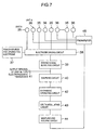
- Fig. 7 is a block diagram showing a schematic construction of an electroacoustic transducer of the digital type according to a third embodiment of the invention and relates to the electroacoustic transducer of the digital type constructed by including the electroacoustic transducing units mentioned in the first and the second embodiment.
- reference numeral 35 denotes units A of the electroacoustic transducer, 36 units B, 37 a power source for driving the electrode, and 38 an electrode driving circuit for performing a connection or disconnection between the electrode driving power source 37 and electrodes of units A 35 in response to a digital driving signal which is supplied from a driving signal supplying circuit 39.
- Reference numeral 40 denotes a sampling circuit, 41 an output terminal of an electroacoustic transducer of the digital type (digital microphone), 42 an arithmetic operating circuit, 43 a delta modulating circuit constructed by a subtractor, a comparator, a local integrator and so on, 44 a sampling and holding circuit, and 45 a preamplifier including an impedance conversion.
- the circuitry within a range from the electrode driving circuit 38 to the output terminal 41 of the digital microphone operates by a clock signal (second clock) of, for example, 44.1 kHz from a viewpoint of matching of a connection to general digital audio equipment.
- a circuitry within a range from the arithmetic operating circuit 42 to sampling and holding circuit 44 operates by a clock signal (first clock) of a higher frequency in consideration of characteristics of the well-known delta modulation. The matching between the two clock signals is performed by the sampling circuit 40.
- an electrostatic loudspeaker as a sounding body, namely, unit A 35 and an electrostatic microphone as a sound receiving sensor, namely, unit B 36 are formed in the same shape and are arranged on a plane.
- the electrostatic microphone and the electrostatic loudspeaker are well known.
- the microphone it is known that its output voltage is proportional to a displacement of the diaphragm by an external sound pressure and an electret surface potential (or polarized voltage).
- an output voltage of the electrostatic loudspeaker is proportional to a driving force that is electrostatically applied to the diaphragm and its magnitude is determined by an electret surface potential (or polarized voltage) and a signal voltage which is applied from the outside and a size of an area of the driving electrode which faces the diaphragm.
- connection state between the electrode driving power source 37 of a predetermined voltage and its group unit is set to "connection" and the driving force is applied.
- a sound pressure of the magnitude according to the numerical value of the digital signal can be radiated.
- the electric/acoustic conversion through the unit A 35 and the digital/analog conversion are simultaneously executed.
- the acoustic signal radiated as mentioned above is detected by the detecting electrodes of the units B 36.
- the units B 36 are distributed and arranged on the same plane as that of the units A 35 and they are mutually additively connected. Therefore, an acoustic signal which is detected becomes an addition value of the outputs of all of the units A 35.
- the operation of so called a delta modulation is performed after the level of the detected acoustic signal was adjusted by the preamplifier 45.
- the signal is sampled by using a high speed clock signal and its sampling value is compared with the one-preceding value, and an output pulse is generated which is set to "+1" when a difference as a comparison result has been increased by a preset threshold value or more, to "-1" when the difference has been decreased, and to "0" when the difference lies within the threshold value (see the sampling and holding circuit 44 and delta modulating circuit 43 shown in Fig. 6).
- An output with the value "+1", "-1", or "0” which is derived as mentioned above is regarded as a binary number and is supplied to the arithmetic operating circuit 42.
- the arithmetic operating circuit 42 adds or subtracts a driving signal and forms a new driving signal.
- a signal that is detected and supplied to the arithmetic operating circuit 42 is caused by only a vibrating force of the acoustic signal which reaches the diaphragm surface of the unit B 36 from the outside.
- the arithmetic operating circuit 42 since the addition or subtraction is always performed so as to reduce the synthesized output of the unit B 36, the unit B 36 remains still against the acoustic signal at a precision within the range of the least significant bit of the digital signal.
- the average value of the pressures on the diaphragm surface which are given by the entering acoustic signal and the synthesized sound pressure that is radiated from the units A 35 via the driving signal supplying circuit 39, electrode driving circuit 38, and driving electrode from the arithmetic operating circuit 42 are balanced within a certain range of errors.
- an output of the arithmetic operating circuit 42 namely, the driving force of the units A 35 is the digitized force and has a magnitude in which a sign is opposite and which is proportional to the acoustic signal with a delay time of one sample. That is, the digital microphone is realized and is shown as a digital type electroacoustic transducer output terminal 41 in Fig. 7. In this case, as for the vibration displacement signal and its preamplifier 45, since the increase or decrease is merely observed, a degree of a requirement about the linearity is set to a degree such that a monotonous increase or decrease in a fairly narrow range is necessary.
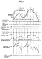
- Fig. 8 schematically shows the above operations.
- Reference numeral 50 denotes a pressure waveform of the acoustic signal which arrives at the diaphragm
- 51 a clock signal (first clock) to perform the delta modulation
- 52 a process to perform the delta modulation to an input
- 53 a delta modulation output
- 54 numerical value displays the delta modulation output 53, 55 results obtained by accumulating and adding the numerical value displays 54
- 56 a threshold value of quantization in the delta modulation.
- reference numeral 57 denotes a clock signal (second clock) for connection to the outside and 58 indicates a value obtained by sampling the accumulated and added results 55 by the clock signal 57.
- the value 58 becomes an electrode driving signal and, at the same time, becomes a digital microphone output signal.
- Reference numeral 59 denotes a waveform display having a shape obtained by sampling the inputted pressure waveform 50.
- Reference numeral 60 denotes a driving force obtained by synthesizing the driving force for the diaphragm by the signal and the input sound pressure and also indicates a vibration displacement of the diaphragm that is proportional to such a driving force, 52' a delta modulating process for the vibration displacement, and 53' a result of this process.
- the result 53' is the same as the result shown in the delta modulation output 53.
- the digital type electroacoustic transducer of the invention can be applied to all of a voice communication system, acoustic equipment, and the like.
- voice transmission systems each having a digital transmission path are shown in Figs. 9A and 9B.
- Fig. 9A shows an example of a voice communication system according to the conventional technique.
- Fig. 98 shows an example of a voice communication system using the digital type electroacoustic transducer of the invention.
- Figs. 9A shows an example of a voice communication system according to the conventional technique.
- Fig. 98 shows an example of a voice communication system using the digital type electroacoustic transducer of the invention.
- reference numeral 61 denotes a microphone by the conventional technique, 62 and 67 linear amplifiers, 63 an analog/digital converter, 64 a digital transmitting circuit, 65 a waveform shaper, 66 a digital/analog converter, 68 a loudspeaker according to the conventional technique, 69 a power source of the system, 70 a digital microphone according to the invention, 71 (two) level adjusters of the digital signal, and 72 a sounding body of the digital type mentioned in the invention.
- a broken line denotes an analog signal path and a solid line indicates a digital signal path.
- Fig. 9B As shown in Fig. 9B, as will be understood because the whole voice communication system has been digitized, the analog/digital converter 63 and digital/analog converter 66 shown in Fig. 9A are omitted. Consequently, the obstacles such as noise, inductive interference, and the like due to the mixture existence of the analog circuit and the digital circuit can be eliminated.
- the circuits such as A/D converter, D/A converter, and the like can be removed.
- the digital type electroacoustic transducer in the invention has the functions of both analog/digital conversion and digital/analog conversion.
- This provides various advantages.
- the system is made free from the obstacles such as noise, inductive interference, and the like due to the existence of a mixed analog circuit and digital circuit, the costs are reduced owing to the standardization of parts, no requirement for adjustment, and the like in terms of the costs, further, high reliability is realized due to the decrease in the number of parts from a viewpoint of the use of the equipment system, and the like.
Landscapes
- Physics & Mathematics (AREA)
- Engineering & Computer Science (AREA)
- Acoustics & Sound (AREA)
- Signal Processing (AREA)
- Circuit For Audible Band Transducer (AREA)
- Electrostatic, Electromagnetic, Magneto- Strictive, And Variable-Resistance Transducers (AREA)
Claims (20)
- Transducteur électroacoustique de type numérique, comprenant :au moins une unité de réception de son (16, 36) comprenant un second diaphragme conducteur (12) et au moins une électrode de détection de vibration (13) agencée presque parallèlement audit diaphragme conducteur (12),un circuit de conversion de niveau et un moyen d'échantillonnage, ledit transducteur étant caractérisé en ce qu'il comprenddes unités d'émission de son (15, 35) d'une pluralité de groupes, chaque unité d'émission de son comprenant un premier diaphragme conducteur (10) et au moins une électrode d'attaque électrostatique (11) agencée presque parallèlement audit premier diaphragme conducteur (10),un circuit d'attaque d'électrode (38) en vue d'une connexion ou d'une déconnexion électrique entre ladite électrode d'attaque électrostatique (11) desdites unités d'émission de son (15, 35) de chaque groupe et une source d'alimentation (37) destinée à attaquer les électrodes,ledit circuit de conversion de niveau (45) destiné à convertir un niveau d'un signal obtenu à partir de ladite au moins une électrode de détection de vibration (13) et représentant un déplacement de vibration dudit diaphragme conducteur (12),ledit moyen d'échantillonnage (40 - 44) destiné à échantillonner un signal de sortie dudit circuit de conversion de niveau, etun circuit de fourniture de signal d'attaque (39) destiné à fournir une sortie dudit moyen d'échantillonnage en tant que signal d'attaque de l'électrode audit circuit d'attaque d'électrode en un format prédéterminé.
- Transducteur selon la revendication 1, comprenant en outre une pluralité desdites unités de réception de son (36) agencées sur un plan presque identique à celui desdites unités d'émission de son (35) de ladite pluralité de groupes.
- Transducteur selon la revendication 1, dans lequel ladite au moins une unité de réception de son (36) comprend un circuit de conversion d'impédance (14) électriquement relié à ladite au moins une électrode de détection de vibration (13).
- Transducteur selon la revendication 1, dans lequel ledit moyen d'échantillonnage comprend :un moyen (44) destiné à échantillonner le signal de sortie dudit circuit de conversion de niveau en utilisant un premier signal d'horloge,un moyen de modulation delta (43) destiné à comparer une valeur dudit signal de sortie échantillonné à une valeur immédiatement précédente et fournir en sortie l'une des impulsions de code "+ 1", "- 1" et "0" sur la base d'un résultat de comparaison en utilisant une valeur de seuil prédéterminée, etun moyen (42, 40) destiné à ajouter de façon cumulée les impulsions de code fournies en sortie à partir dudit moyen de modulation delta (43) et à échantillonner un résultat d'addition en utilisant un second signal d'horloge qui est adapté à un équipement externe qui est électriquement relié audit transducteur électroacoustique de type numérique.
- Transducteur selon la revendication 4, dans lequel ledit premier signal d'horloge présente une fréquence qui est au moins deux fois plus élevée que celle dudit second signal d'horloge.
- Transducteur selon la revendication 1, dans lequel un nombre d'unités d'émission de son compris dans le ne groupe parmi lesdites unités d'émission de son (35) de ladite pluralité de groupes est proportionnel à 2n.
- Transducteur selon la revendication 1, dans lequel un produit d'un nombre d'unités d'émission de son compris dans le ne groupe parmi lesdites unités d'émission de son (35) de ladite pluralité de groupes et d'une tension de ladite source d'alimentation (37) qui est appliquée auxdites unités d'émission dudit ne groupe, est proportionnel à 2n en correspondance avec une position d'un chiffre binaire d'un signal numérique d'entrée.
- Transducteur selon la revendication 1, dans lequel une capacité électrostatique qui est formée par ladite au moins une électrode de détection de vibration (21) et ledit diaphragme conducteur (20) fait partie d'un circuit de résonance qui résonne à une fréquence qui est au moins dix fois plus élevée que celle du signal d'attaque d'électrode dans ladite au moins une électrode d'attaque électrostatique (21), et une variation de ladite capacité électrostatique qui est provoquée par une vibration dudit diaphragme conducteur (20) est convertie en une variation du signal électrique et est utilisée en tant que ledit signal représentant le déplacement de vibration dudit second diaphragme conducteur (20).
- Transducteur selon la revendication 1, dans lequel chacune de ladite au moins une électrode d'attaque électrostatique (11) et de ladite au moins une électrode de détection de vibration (13) comprend un film fixé à au moins une partie d'une surface qui est en regard d'un diaphragme respectif parmi lesdits diaphragmes conducteurs et sur lequel un électret a été formé tout en y collant des charges.
- Transducteur selon la revendication 8, dans lequel ledit film comprend un film de résine fluorée sur lequel les charges ont été collées par un dispositif de dispersion à effet corona.
- Transducteur selon la revendication 1, dans lequel chacun desdits diaphragmes conducteurs comprend un film sur lequel un électret a été formé en collant un matériau conducteur sur une première surface et en collant des charges sur l'autre surface.
- Transducteur selon la revendication 11, dans lequel ledit film comprend un film de résine fluorée sur lequel les charges ont été collées par un dispositif de dispersion à effet corona.
- Transducteur selon la revendication 1, dans lequel chacun desdits diaphragmes conducteurs comprend deux films sur chacun desquels un électret a été formé en collant un matériau conducteur sur une première surface et en collant des charges sur l'autre surface, et lesdits deux films sont collés l'un à l'autre sur ladite première surface sur laquelle est collé ledit matériau conducteur.
- Transducteur selon la revendication 13, dans lequel chacun desdits deux films comprend un film de résine fluorée sur lequel les charges ont été collées par un dispositif de dispersion à effet corona.
- Transducteur selon la revendication 1, dans lequel chacun desdits diaphragmes conducteurs comprend deux films sur chacun desquels un électret a été formé en collant des charges sur une première surface, et lesdits deux films sont collés l'un à l'autre sur ladite première surface sur laquelle sont collées lesdites charges.
- Transducteur selon la revendication 14, dans lequel chacun desdits deux films comprend un film de résine fluorée sur lequel les charges ont été collées par un dispositif de dispersion à effet corona.
- Transducteur selon la revendication 1, dans lequel au moins l'une desdites unités de réception (16, 36) comprend au moins une électrode fixe (21) agencée presque parallèlement audit second diaphragme conducteur (20),
une première bobine d'inductance (27) comportant une première borne électriquement reliée à ladite électrode fixe (21) d'au moins une unité de transducteur électroacoustique et une seconde borne destinée à recevoir un signal d'attaque d'électrode de façon à bloquer une haute fréquence,
un condensateur (26) comportant une première borne électriquement reliée à ladite électrode fixe (21) d'au moins une unité de transducteur électroacoustique de façon à bloquer une basse fréquence,
une seconde bobine d'inductance (22) électriquement reliée entre une seconde borne dudit condensateur (26) et ledit second diaphragme conducteur (20) d'au moins une unité de transducteur électroacoustique pour former un circuit de résonance en série présentant une capacité électrostatique formée par ledit diaphragme conducteur (20) et ladite électrode fixe (21),
un moyen de fourniture de signal (23) destiné à fournir un signal présentant une fréquence prédéterminée audit circuit de résonance en série, et
un moyen de détection de vibration (24) destiné à détecter une vibration dudit diaphragme conducteur (20) sur la base d'une tension d'au moins un point dudit circuit de résonance en série pour fournir en sortie un signal de détection de vibration. - Transducteur selon la revendication 17, dans lequel ladite fréquence prédéterminée est au moins dix fois plus élevée que celle dudit signal d'attaque d'électrode.
- Transducteur selon la revendication 17, dans lequel le nombre d'unités de transducteur électroacoustique compris dans le ne groupe parmi lesdites unités de transducteur électroacoustique de ladite pluralité de groupes est proportionnel à 2n.
- Transducteur de type numérique selon la revendication 17, dans lequel un produit d'un nombre d'unités de transducteur électroacoustique compris dans le ne groupe parmi lesdites unités de transducteur électroacoustique de ladite pluralité de groupes et de la tension dudit signal d'attaque d'électrode qui est appliqué aux unités de transducteur électroacoustique dudit ne groupe est proportionnel à 2n en correspondance avec une position d'un chiffre binaire d'un signal numérique d'entrée.
Applications Claiming Priority (4)
| Application Number | Priority Date | Filing Date | Title |
|---|---|---|---|
| JP3308198 | 1998-02-16 | ||
| JP3308198 | 1998-02-16 | ||
| JP13505998 | 1998-05-18 | ||
| JP13505998A JP3377173B2 (ja) | 1998-02-16 | 1998-05-18 | ディジタル式電気音響変換器 |
Publications (3)
| Publication Number | Publication Date |
|---|---|
| EP0936837A2 EP0936837A2 (fr) | 1999-08-18 |
| EP0936837A3 EP0936837A3 (fr) | 1999-09-15 |
| EP0936837B1 true EP0936837B1 (fr) | 2004-06-30 |
Family
ID=26371719
Family Applications (1)
| Application Number | Title | Priority Date | Filing Date |
|---|---|---|---|
| EP99103004A Expired - Lifetime EP0936837B1 (fr) | 1998-02-16 | 1999-02-15 | Transducteur électroacoustique de type digital |
Country Status (5)
| Country | Link |
|---|---|
| US (1) | US6125189A (fr) |
| EP (1) | EP0936837B1 (fr) |
| JP (1) | JP3377173B2 (fr) |
| CN (1) | CN1168350C (fr) |
| DE (1) | DE69918344T2 (fr) |
Families Citing this family (24)
| Publication number | Priority date | Publication date | Assignee | Title |
|---|---|---|---|---|
| US6449370B1 (en) * | 1998-02-16 | 2002-09-10 | Matsushita Electric Industrial Co., Ltd. | Digital electro-acoustic transducer |
| JP3456924B2 (ja) * | 1999-07-01 | 2003-10-14 | アオイ電子株式会社 | マイクロホン装置 |
| US7058463B1 (en) | 2000-12-29 | 2006-06-06 | Nokia Corporation | Method and apparatus for implementing a class D driver and speaker system |
| US20020131608A1 (en) * | 2001-03-01 | 2002-09-19 | William Lobb | Method and system for providing digitally focused sound |
| US6853733B1 (en) * | 2003-06-18 | 2005-02-08 | National Semiconductor Corporation | Two-wire interface for digital microphones |
| JP2006105859A (ja) * | 2004-10-07 | 2006-04-20 | Tem-Tech Kenkyusho:Kk | フッ素樹脂薄膜ダイヤフラム圧力センサおよびその製造方法 |
| JP4670050B2 (ja) * | 2004-11-26 | 2011-04-13 | 国立大学法人 東京大学 | エレクトレット及び静電誘導型変換素子 |
| EP1902532A4 (fr) * | 2005-07-14 | 2012-08-22 | Scosche Ind Inc | Source multimedia sans fil pour communication avec des dispositifs sur un bus de donnees de vehicule |
| US8457338B2 (en) | 2006-05-22 | 2013-06-04 | Audio Pixels Ltd. | Apparatus and methods for generating pressure waves |
| MY151910A (en) * | 2006-05-22 | 2014-07-31 | Audio Pixels Holdings Ltd | Volume and tone control in direct digital speakers |
| ES2388392T3 (es) * | 2006-05-22 | 2012-10-15 | Audio Pixels Ltd. | Aparato de altavoz digital directo que tiene un patrón de directividad deseado |
| US8780673B2 (en) | 2007-11-21 | 2014-07-15 | Audio Pixels Ltd. | Digital speaker apparatus |
| CN101959105B (zh) * | 2009-07-12 | 2014-01-15 | 苏州敏芯微电子技术有限公司 | 静电式扬声器 |
| DK2545715T3 (da) | 2010-03-11 | 2014-09-01 | Audio Pixels Ltd | Elektrostatiske parallelle pladeaktuatorer, hvis bevægelige elementer alene drives ved elektrostatisk kraft, og nyttige fremgangsmåder i forbindelse dermed |
| JP5871336B2 (ja) | 2010-11-26 | 2016-03-01 | オーディオ ピクセルズ エルティーディー.Audio Pixels Ltd. | アクチュエータアレイにおける個別のアドレス指定およびノイズ低減のための装置および方法 |
| JP5701142B2 (ja) * | 2011-05-09 | 2015-04-15 | 株式会社オーディオテクニカ | マイクロホン |
| DK2856770T3 (en) | 2012-05-25 | 2018-10-22 | Audio Pixels Ltd | SYSTEM, PROCEDURE AND COMPUTER PROGRAM PRODUCT TO CONTROL A SET OF ACTUATOR ELEMENTS |
| WO2013175476A1 (fr) | 2012-05-25 | 2013-11-28 | Audio Pixels Ltd. | Système, procédé et produit-programme informatique pour contrôler un groupe de réseaux d'actionneurs en vue de produire un effet physique |
| EP3284266B1 (fr) | 2015-04-15 | 2021-02-17 | Audio Pixels Ltd. | Procédés et systèmes permettant de détecter au moins la position d'un objet dans l'espace |
| US10665219B2 (en) | 2018-01-31 | 2020-05-26 | Zerosound Systems Inc. | Apparatus and method for active noise reduction |
| US11151975B2 (en) | 2018-01-31 | 2021-10-19 | Zerosound Systems Inc. | Apparatus and method for sound wave generation |
| US20190251944A1 (en) * | 2018-01-31 | 2019-08-15 | Raymond Sobol | System and Method For Altering Sound Waves |
| CN112334867B (zh) | 2018-05-24 | 2025-11-11 | 纽约州立大学研究基金会 | 电容传感器 |
| CN112601155A (zh) * | 2020-12-10 | 2021-04-02 | 南京汉得利智能科技有限公司 | 一种数字参量阵扬声器的方法和系统 |
Family Cites Families (15)
| Publication number | Priority date | Publication date | Assignee | Title |
|---|---|---|---|---|
| CH466376A (de) * | 1968-03-01 | 1968-12-15 | Ibm | Anordnung zur Umwandlung von Drücken in digitale elektrische Signale |
| FR2050890A5 (fr) * | 1969-06-27 | 1971-04-02 | Bernard Patrice | |
| JPS606594B2 (ja) * | 1979-04-05 | 1985-02-19 | 松下電器産業株式会社 | デイジタルマイクロホン |
| JPS57149000U (fr) * | 1981-03-12 | 1982-09-18 | ||
| FR2521382A2 (fr) * | 1982-02-09 | 1983-08-12 | Lectret Sa | Transducteur acoustique |
| JPS58171200A (ja) * | 1982-03-31 | 1983-10-07 | Toshiba Corp | 静電型電気−音響変換器 |
| JPS59202799A (ja) * | 1983-04-30 | 1984-11-16 | Onkyo Corp | 静電型電気音響変換器の駆動方式 |
| NL8303185A (nl) * | 1983-09-15 | 1985-04-01 | Philips Nv | Hybried luidsprekersysteem eventueel met een of meer korrektieketens. |
| JP2816856B2 (ja) * | 1989-04-14 | 1998-10-27 | 日通工株式会社 | ディジタルマイクロホン |
| JPH04167798A (ja) * | 1990-10-31 | 1992-06-15 | Nitsuko Corp | ディジタルマイクロホン |
| JP2555936B2 (ja) * | 1993-06-30 | 1996-11-20 | 日本電気株式会社 | ディジタルマイクロホン |
| JPH07227000A (ja) * | 1994-02-15 | 1995-08-22 | Audio Technica Corp | 静電型電気音響変換器 |
| FR2716760B1 (fr) * | 1994-02-28 | 1996-03-22 | Thomson Csf | Convertisseur analogique-numérique du type SIGMADELTA de degré élevé. |
| US5566135A (en) * | 1995-07-11 | 1996-10-15 | The United States Of America As Represented By The Secretary Of The Navy | Digital transducer |
| DE69527790D1 (de) * | 1995-09-29 | 2002-09-19 | St Microelectronics Srl | Digitale mikrophonische Vorrichtung |
-
1998
- 1998-05-18 JP JP13505998A patent/JP3377173B2/ja not_active Expired - Lifetime
-
1999
- 1999-02-11 US US09/247,872 patent/US6125189A/en not_active Expired - Lifetime
- 1999-02-15 CN CNB991022718A patent/CN1168350C/zh not_active Expired - Lifetime
- 1999-02-15 EP EP99103004A patent/EP0936837B1/fr not_active Expired - Lifetime
- 1999-02-15 DE DE69918344T patent/DE69918344T2/de not_active Expired - Lifetime
Also Published As
| Publication number | Publication date |
|---|---|
| DE69918344D1 (de) | 2004-08-05 |
| EP0936837A3 (fr) | 1999-09-15 |
| EP0936837A2 (fr) | 1999-08-18 |
| JP3377173B2 (ja) | 2003-02-17 |
| CN1234715A (zh) | 1999-11-10 |
| JPH11298987A (ja) | 1999-10-29 |
| CN1168350C (zh) | 2004-09-22 |
| US6125189A (en) | 2000-09-26 |
| DE69918344T2 (de) | 2005-06-30 |
Similar Documents
| Publication | Publication Date | Title |
|---|---|---|
| US6125189A (en) | Electroacoustic transducer of digital type | |
| US7245734B2 (en) | Directional microphone | |
| EP0107843B1 (fr) | Détecteur d'accélération de vibration | |
| CN104837092B (zh) | 用于电声通信设备的回声消除方法和总成 | |
| CN101543089A (zh) | 语音输入装置及其制造方法、信息处理系统 | |
| CN104170404A (zh) | 具有运动控制的换能器 | |
| Pauer | A flexible piezoelectric material for hydrophones and other dynamic pressure transducers | |
| US10126181B2 (en) | Temperature sensor, electronic unit interacting with such a sensor, and related method and computer program | |
| EP0701386A2 (fr) | Haut-parleur et son dispositif de commande | |
| US20040156520A1 (en) | Miniature digital transducer with reduced number of external terminals | |
| US6697493B1 (en) | Process and arrangement for converting an acoustic signal to an electrical signal | |
| JPH10126886A (ja) | ディジタル式電気音響変換器 | |
| US6442194B1 (en) | Digital telephone transmitter/receiver | |
| GB2330725A (en) | Single-bit microphone | |
| JP3499122B2 (ja) | ディジタル電気音響変換装置 | |
| US6449370B1 (en) | Digital electro-acoustic transducer | |
| EP0966178B1 (fr) | Transducteur électroacoustique digital | |
| Yasuno et al. | A basic concept of direct converting digital microphone | |
| KR100883052B1 (ko) | 무선 마이크로폰 | |
| JP3049815B2 (ja) | ディジタルマイクロホン | |
| JPS63109700A (ja) | 発音体 | |
| JPH1056679A (ja) | 音波検出装置及び音波処理装置 | |
| Fraden | Microphones | |
| JP2001059786A (ja) | 圧力変換装置 | |
| JP2001036994A (ja) | 静電型電気音響変換器 |
Legal Events
| Date | Code | Title | Description |
|---|---|---|---|
| PUAI | Public reference made under article 153(3) epc to a published international application that has entered the european phase |
Free format text: ORIGINAL CODE: 0009012 |
|
| PUAL | Search report despatched |
Free format text: ORIGINAL CODE: 0009013 |
|
| 17P | Request for examination filed |
Effective date: 19990215 |
|
| AK | Designated contracting states |
Kind code of ref document: A2 Designated state(s): DE FR GB |
|
| AX | Request for extension of the european patent |
Free format text: AL;LT;LV;MK;RO;SI |
|
| AK | Designated contracting states |
Kind code of ref document: A3 Designated state(s): AT BE CH CY DE DK ES FI FR GB GR IE IT LI LU MC NL PT SE |
|
| AX | Request for extension of the european patent |
Free format text: AL;LT;LV;MK;RO;SI |
|
| AKX | Designation fees paid |
Free format text: DE FR GB |
|
| 17Q | First examination report despatched |
Effective date: 20021212 |
|
| GRAP | Despatch of communication of intention to grant a patent |
Free format text: ORIGINAL CODE: EPIDOSNIGR1 |
|
| GRAS | Grant fee paid |
Free format text: ORIGINAL CODE: EPIDOSNIGR3 |
|
| GRAA | (expected) grant |
Free format text: ORIGINAL CODE: 0009210 |
|
| AK | Designated contracting states |
Kind code of ref document: B1 Designated state(s): DE FR GB |
|
| REG | Reference to a national code |
Ref country code: GB Ref legal event code: FG4D |
|
| REF | Corresponds to: |
Ref document number: 69918344 Country of ref document: DE Date of ref document: 20040805 Kind code of ref document: P |
|
| ET | Fr: translation filed | ||
| PLBE | No opposition filed within time limit |
Free format text: ORIGINAL CODE: 0009261 |
|
| STAA | Information on the status of an ep patent application or granted ep patent |
Free format text: STATUS: NO OPPOSITION FILED WITHIN TIME LIMIT |
|
| 26N | No opposition filed |
Effective date: 20050331 |
|
| REG | Reference to a national code |
Ref country code: FR Ref legal event code: PLFP Year of fee payment: 18 |
|
| REG | Reference to a national code |
Ref country code: FR Ref legal event code: PLFP Year of fee payment: 19 |
|
| REG | Reference to a national code |
Ref country code: FR Ref legal event code: PLFP Year of fee payment: 20 |
|
| PGFP | Annual fee paid to national office [announced via postgrant information from national office to epo] |
Ref country code: DE Payment date: 20180130 Year of fee payment: 20 Ref country code: GB Payment date: 20180214 Year of fee payment: 20 |
|
| PGFP | Annual fee paid to national office [announced via postgrant information from national office to epo] |
Ref country code: FR Payment date: 20180111 Year of fee payment: 20 |
|
| REG | Reference to a national code |
Ref country code: DE Ref legal event code: R071 Ref document number: 69918344 Country of ref document: DE |
|
| REG | Reference to a national code |
Ref country code: GB Ref legal event code: PE20 Expiry date: 20190214 |
|
| PG25 | Lapsed in a contracting state [announced via postgrant information from national office to epo] |
Ref country code: GB Free format text: LAPSE BECAUSE OF EXPIRATION OF PROTECTION Effective date: 20190214 |