EP0938009A1 - Optische Anordnung und Projektionsbelichtungsanlage der Mikrolithographie mit passiver thermischer Kompensation - Google Patents
Optische Anordnung und Projektionsbelichtungsanlage der Mikrolithographie mit passiver thermischer Kompensation Download PDFInfo
- Publication number
- EP0938009A1 EP0938009A1 EP99100845A EP99100845A EP0938009A1 EP 0938009 A1 EP0938009 A1 EP 0938009A1 EP 99100845 A EP99100845 A EP 99100845A EP 99100845 A EP99100845 A EP 99100845A EP 0938009 A1 EP0938009 A1 EP 0938009A1
- Authority
- EP
- European Patent Office
- Prior art keywords
- optical element
- projection exposure
- exposure system
- heat
- optical
- Prior art date
- Legal status (The legal status is an assumption and is not a legal conclusion. Google has not performed a legal analysis and makes no representation as to the accuracy of the status listed.)
- Granted
Links
- 230000003287 optical effect Effects 0.000 title claims abstract description 50
- 238000001393 microlithography Methods 0.000 title claims abstract description 7
- 238000001816 cooling Methods 0.000 claims description 25
- 239000000463 material Substances 0.000 claims description 19
- 230000005855 radiation Effects 0.000 claims description 9
- 230000000694 effects Effects 0.000 claims description 5
- 238000000265 homogenisation Methods 0.000 claims description 2
- 210000001747 pupil Anatomy 0.000 claims 1
- 241000219739 Lens Species 0.000 description 35
- 239000007789 gas Substances 0.000 description 4
- 238000005286 illumination Methods 0.000 description 4
- 240000004322 Lens culinaris Species 0.000 description 3
- 241000022563 Rema Species 0.000 description 3
- BQCADISMDOOEFD-UHFFFAOYSA-N Silver Chemical compound [Ag] BQCADISMDOOEFD-UHFFFAOYSA-N 0.000 description 3
- 229910052782 aluminium Inorganic materials 0.000 description 3
- XAGFODPZIPBFFR-UHFFFAOYSA-N aluminium Chemical compound [Al] XAGFODPZIPBFFR-UHFFFAOYSA-N 0.000 description 3
- 238000010438 heat treatment Methods 0.000 description 3
- 230000031700 light absorption Effects 0.000 description 3
- 238000000034 method Methods 0.000 description 3
- 229910052709 silver Inorganic materials 0.000 description 3
- 239000004332 silver Substances 0.000 description 3
- VYPSYNLAJGMNEJ-UHFFFAOYSA-N Silicium dioxide Chemical compound O=[Si]=O VYPSYNLAJGMNEJ-UHFFFAOYSA-N 0.000 description 2
- 230000004075 alteration Effects 0.000 description 2
- 238000004364 calculation method Methods 0.000 description 2
- 239000004020 conductor Substances 0.000 description 2
- 239000001307 helium Substances 0.000 description 2
- 229910052734 helium Inorganic materials 0.000 description 2
- SWQJXJOGLNCZEY-UHFFFAOYSA-N helium atom Chemical compound [He] SWQJXJOGLNCZEY-UHFFFAOYSA-N 0.000 description 2
- 230000001105 regulatory effect Effects 0.000 description 2
- 238000004088 simulation Methods 0.000 description 2
- RYGMFSIKBFXOCR-UHFFFAOYSA-N Copper Chemical compound [Cu] RYGMFSIKBFXOCR-UHFFFAOYSA-N 0.000 description 1
- 235000014647 Lens culinaris subsp culinaris Nutrition 0.000 description 1
- 239000006244 Medium Thermal Substances 0.000 description 1
- 239000006094 Zerodur Substances 0.000 description 1
- 238000010521 absorption reaction Methods 0.000 description 1
- 230000006978 adaptation Effects 0.000 description 1
- 239000000853 adhesive Substances 0.000 description 1
- 230000001070 adhesive effect Effects 0.000 description 1
- 238000011161 development Methods 0.000 description 1
- 230000018109 developmental process Effects 0.000 description 1
- 238000005516 engineering process Methods 0.000 description 1
- 239000003292 glue Substances 0.000 description 1
- 239000004973 liquid crystal related substance Substances 0.000 description 1
- 229910052751 metal Inorganic materials 0.000 description 1
- 239000002184 metal Substances 0.000 description 1
- 239000010453 quartz Substances 0.000 description 1
- 238000007493 shaping process Methods 0.000 description 1
- 239000010454 slate Substances 0.000 description 1
- 239000007787 solid Substances 0.000 description 1
- 238000010792 warming Methods 0.000 description 1
Images

Classifications
-
- G—PHYSICS
- G03—PHOTOGRAPHY; CINEMATOGRAPHY; ANALOGOUS TECHNIQUES USING WAVES OTHER THAN OPTICAL WAVES; ELECTROGRAPHY; HOLOGRAPHY
- G03F—PHOTOMECHANICAL PRODUCTION OF TEXTURED OR PATTERNED SURFACES, e.g. FOR PRINTING, FOR PROCESSING OF SEMICONDUCTOR DEVICES; MATERIALS THEREFOR; ORIGINALS THEREFOR; APPARATUS SPECIALLY ADAPTED THEREFOR
- G03F7/00—Photomechanical, e.g. photolithographic, production of textured or patterned surfaces, e.g. printing surfaces; Materials therefor, e.g. comprising photoresists; Apparatus specially adapted therefor
- G03F7/70—Microphotolithographic exposure; Apparatus therefor
- G03F7/70216—Mask projection systems
- G03F7/70358—Scanning exposure, i.e. relative movement of patterned beam and workpiece during imaging
-
- G—PHYSICS
- G02—OPTICS
- G02B—OPTICAL ELEMENTS, SYSTEMS OR APPARATUS
- G02B7/00—Mountings, adjusting means, or light-tight connections, for optical elements
- G02B7/02—Mountings, adjusting means, or light-tight connections, for optical elements for lenses
- G02B7/028—Mountings, adjusting means, or light-tight connections, for optical elements for lenses with means for compensating for changes in temperature or for controlling the temperature; thermal stabilisation
-
- G—PHYSICS
- G03—PHOTOGRAPHY; CINEMATOGRAPHY; ANALOGOUS TECHNIQUES USING WAVES OTHER THAN OPTICAL WAVES; ELECTROGRAPHY; HOLOGRAPHY
- G03F—PHOTOMECHANICAL PRODUCTION OF TEXTURED OR PATTERNED SURFACES, e.g. FOR PRINTING, FOR PROCESSING OF SEMICONDUCTOR DEVICES; MATERIALS THEREFOR; ORIGINALS THEREFOR; APPARATUS SPECIALLY ADAPTED THEREFOR
- G03F7/00—Photomechanical, e.g. photolithographic, production of textured or patterned surfaces, e.g. printing surfaces; Materials therefor, e.g. comprising photoresists; Apparatus specially adapted therefor
- G03F7/70—Microphotolithographic exposure; Apparatus therefor
- G03F7/70058—Mask illumination systems
- G03F7/70091—Illumination settings, i.e. intensity distribution in the pupil plane or angular distribution in the field plane; On-axis or off-axis settings, e.g. annular, dipole or quadrupole settings; Partial coherence control, i.e. sigma or numerical aperture [NA]
- G03F7/70108—Off-axis setting using a light-guiding element, e.g. diffractive optical elements [DOEs] or light guides
-
- G—PHYSICS
- G03—PHOTOGRAPHY; CINEMATOGRAPHY; ANALOGOUS TECHNIQUES USING WAVES OTHER THAN OPTICAL WAVES; ELECTROGRAPHY; HOLOGRAPHY
- G03F—PHOTOMECHANICAL PRODUCTION OF TEXTURED OR PATTERNED SURFACES, e.g. FOR PRINTING, FOR PROCESSING OF SEMICONDUCTOR DEVICES; MATERIALS THEREFOR; ORIGINALS THEREFOR; APPARATUS SPECIALLY ADAPTED THEREFOR
- G03F7/00—Photomechanical, e.g. photolithographic, production of textured or patterned surfaces, e.g. printing surfaces; Materials therefor, e.g. comprising photoresists; Apparatus specially adapted therefor
- G03F7/70—Microphotolithographic exposure; Apparatus therefor
- G03F7/70216—Mask projection systems
- G03F7/70241—Optical aspects of refractive lens systems, i.e. comprising only refractive elements
-
- G—PHYSICS
- G03—PHOTOGRAPHY; CINEMATOGRAPHY; ANALOGOUS TECHNIQUES USING WAVES OTHER THAN OPTICAL WAVES; ELECTROGRAPHY; HOLOGRAPHY
- G03F—PHOTOMECHANICAL PRODUCTION OF TEXTURED OR PATTERNED SURFACES, e.g. FOR PRINTING, FOR PROCESSING OF SEMICONDUCTOR DEVICES; MATERIALS THEREFOR; ORIGINALS THEREFOR; APPARATUS SPECIALLY ADAPTED THEREFOR
- G03F7/00—Photomechanical, e.g. photolithographic, production of textured or patterned surfaces, e.g. printing surfaces; Materials therefor, e.g. comprising photoresists; Apparatus specially adapted therefor
- G03F7/70—Microphotolithographic exposure; Apparatus therefor
- G03F7/708—Construction of apparatus, e.g. environment aspects, hygiene aspects or materials
- G03F7/70808—Construction details, e.g. housing, load-lock, seals or windows for passing light in or out of apparatus
- G03F7/70825—Mounting of individual elements, e.g. mounts, holders or supports
-
- G—PHYSICS
- G03—PHOTOGRAPHY; CINEMATOGRAPHY; ANALOGOUS TECHNIQUES USING WAVES OTHER THAN OPTICAL WAVES; ELECTROGRAPHY; HOLOGRAPHY
- G03F—PHOTOMECHANICAL PRODUCTION OF TEXTURED OR PATTERNED SURFACES, e.g. FOR PRINTING, FOR PROCESSING OF SEMICONDUCTOR DEVICES; MATERIALS THEREFOR; ORIGINALS THEREFOR; APPARATUS SPECIALLY ADAPTED THEREFOR
- G03F7/00—Photomechanical, e.g. photolithographic, production of textured or patterned surfaces, e.g. printing surfaces; Materials therefor, e.g. comprising photoresists; Apparatus specially adapted therefor
- G03F7/70—Microphotolithographic exposure; Apparatus therefor
- G03F7/708—Construction of apparatus, e.g. environment aspects, hygiene aspects or materials
- G03F7/70858—Environment aspects, e.g. pressure of beam-path gas, temperature
- G03F7/70883—Environment aspects, e.g. pressure of beam-path gas, temperature of optical system
- G03F7/70891—Temperature
Definitions
- the invention relates to an optical arrangement with a Light source and an optical element, in particular one Projection exposure system of microlithography, at a non-rotationally symmetrical thermal influence by the radiation from the light source occurs.
- This situation is of particular importance for wafer scanners with a slit-shaped image field - either a narrow one Rectangle with a ratio of width to length e.g. of typically 1: 5 up to 1: 9, or especially with mirror systems circular arc.
- the object of the invention is that by light absorption and the resulting warming caused a change in the Properties of optical elements with the simplest possible Significantly reduce or symmetrize means, especially in projection exposure systems.
- the invention goes with asymmetrical cooling of proven, and especially in projection exposure systems Previously exaggerated building principles of the frames with high symmetry.
- Claims 2 and 4 see cooling by parts without Version function before, so that the actual version again can remain symmetrical.
- Figure 1 shows a lens frame 2, in the a lens 1 through a plurality of webs 21-28 (shown eight) largely tension-free and precisely fixed in position is held.
- the webs 21-28 spoke, tabs
- the webs 21-28 are with the Edge of the lens 1 glued or by other joining methods connected.
- the lens 1 In a slit-shaped cross section 10, the lens 1 illuminated.
- the problem is that the lens materials have significant absorption and consequently in Cross section 10 there is a significant supply of heat.
- the one with it associated temperature increase causes a change in Refractive index and an additional one due to thermal expansion Deformation. Overall, there is a change in the lens effect with astigmatic effect.
- the cooling takes place only to a small extent via the Ambient gas (usually with projection exposure systems Helium) and by heat radiation.
- the heat is primarily over the lens body 1, the joint (adhesive) and the gas in the Surrounding the joint and the webs 21-28 on the socket 2 dissipated.
- the webs 21-28 are now in this example different materials, which makes them different Have thermal conductivity.
- they are the slot-shaped cross section 10 of the nearest webs 21, 25 Silver with very good thermal conductivity, the most distant 23, 27 made of lead with low thermal conductivity and the intermediate Bars 22, 24, 26, 28 made of aluminum with medium Thermal conductivity.
- the temperature distribution in the lens 1 is thus relatively lowered between the webs 21, 23 and between the webs 23, 27 relatively raised, resulting in a - at least partially - homogenization and symmetrization of the Temperature distribution and a reduced optical disturbance Properties of lens 1 results.
- FIG 2 is a "dipole" illumination of the Lens with two eccentric light spots 101, 102 shown, as in the area of the aperture level and equivalent levels of Projection exposure systems with symmetrical slate Lighting occurs. This also results in astigmatic Errors due to light absorption caused by the passive compensating Cooling can be reduced.
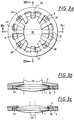
- Figure 3a-c shows a variant of the invention with a additional, only intended for compensating cooling, heat-conducting element 3.
- Lens 1 and socket 2 are for example with even webs or with selectively cooling webs 21-28 connected according to Figure 1 or 2. Any other frame technique is equally applicable.
- the heat-conducting element 3 is a good heat conductor with the holder 2 firmly connected and covers parts of the lens 1, which not be penetrated by light, so outside of it too Illuminated surface 10 shown here as a slot.
- This overlap is preferably carried out without contact, for example with a distance of about 0.1 mm, so that with the mediation of Filling gas good heat transfer is guaranteed at the same time, however, no voltages are entered into the lens 1 can be.
- Better heat conduction arises, of course, if the gap between lens 1 and thermally conductive element 3 with Glue, a gel, liquid crystals or the like, if possible little tension-transmitting material is filled.
- Elements 3 with a plurality of fingers or spokes can also their width, shape and distribution for setting the Heat conduction can be used. Also when running as continuous disc or pinhole can be the thickness of the heat conductive Elements are carried out in different locations. Also it is possible to use the individual fingers analogously to the webs 21-28 according to Figure 1 from different heat-conducting materials do. Of course, the heat-conducting element 3 can also be arranged on both sides of the lens 1.
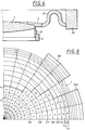
- FIG. 4 shows a representation corresponding to FIG. 3b Possibility of how the cooling element 3 in material or form-fitting Can be brought into contact with lens 1 without the mechanical properties of the version 2 and the Connecting parts 21 are disturbed.
- the cooling element 3 becomes this equipped with a flexible heat-conducting cable 30 - e.g. a copper wire - and connected to a heat sink 20.
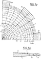
- FIG. 5a shows the finite element model of a Quadrants of a lens 1 made of quartz glass (center thickness 14.4 mm, upper radius of curvature 1600 mm, lower radius of curvature 220 mm - biconvex -, diameter 160 mm).
- Eight solid tabs (51, 52, 53) made of aluminum are evenly distributed in the from the Section 5b recognizable arranged on the lens 1. They are 30 mm wide, 2 mm thick above the lens and 6 mm radially covering, outside they are 8 mm long radially in 4 mm thick. At the outer edge they are kept at the base temperature, e.g. thanks to flexible, heat-conducting strands 50.
- a heat input by light absorption of 1 W / cm 2 is applied on the surface of the lens 1 shown in the area 4, which approximates a rectangle in the selected element division.
- the temperature increase in the center then reaches 7.6 milligrades.
- the isotherms 0.1 to 0.9 are shown, which show the course of the lines with the corresponding fraction of this temperature increase. With higher heat input, the temperature increase scales linearly over a wide range.
- the cooling tabs lying on the Y axis omitted.
- the cooling tabs 510 lying on the X axis are doubled in width and additionally from the better heat-conducting Silver made.
- the tabs 52 remain in between unchanged, as well as the heat supply in area 4.
- the temperature increase at the center 9.2 is now Milligrad.
- the isotherms are up to about 0.7 times that maximum temperature increase and half the lens diameter now well rotationally symmetrical.
- the mechanical version of the lens 1 can either by Cooling tabs 510, 52 are done, or it is any Setting technology provided, which is preferably comparatively has low heat conduction.
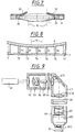
- Figure 7 shows a variant similar to Figure 3a-c, in which the fingers 31, 32 of the heat-conducting element made of bimetal - two layers of material with different thermal expansion - are executed.
- the bimetallic strip 31 is bent away from the lens 1 and can absorb only a little heat.
- the bimetal strip 32 is stretched and is at a short distance from the lens 1, so that it can dissipate a lot of heat.
- FIG. 8 shows a specially adapted to a mirror 6 Execution.
- the mirror 6 is on a bracket 7 on supports 71 to 77 distributed on its back - individual webs or support rings - supported.
- the different thermal expansion of the materials for the Supports 71-77 can also be used in a targeted manner Deformations of the mirror 6 due to the heating compensate, or to bring about specifically. in the latter case can then interfere with other optical Elements that interact with the mirror 6 in a system, be compensated.
- FIG 9 shows the complete optical system of a projection exposure system the microlithography in the schematic Overview.
- a DUV excimer laser serves as the light source 61 beam-shaping optics 62 with zoom axicon lens 63, optional an aperture 64 (changeable, conventional, ring aperture, Dipole, quadrupole aperture) and a homogenizing quartz rod 65 illuminates the REMA aperture 66 homogeneously, which is due to the following REMA lens 67 as a sharply edged homogeneous Illuminated spot, especially as a narrow scan slot, on the Mask 68 is shown.
- the following reducing projection lens 69 forms the Mask 68 on the wafer 70.
- the field-close lenses 671 and 672 of the REMA objective 67 and 692 of the projection objective 69 now preferred optical elements on which the invention Cooling is used. This cooling reduces the one Scanner in which mask 68 and wafer 70 are scanned synchronously are illuminated due to the narrow slit-shaped Aberrations.
- the lens 691 is next to the aperture diaphragm 690 of the projection objective 69 arranged. It is characterized by special types of lighting, e.g. Dipole aperture, particularly loaded (see Figure 2). However, due to the asymmetrical cooling according to the invention this interference can also be reduced.
Landscapes
- Physics & Mathematics (AREA)
- General Physics & Mathematics (AREA)
- Health & Medical Sciences (AREA)
- Engineering & Computer Science (AREA)
- Environmental & Geological Engineering (AREA)
- Epidemiology (AREA)
- Public Health (AREA)
- Life Sciences & Earth Sciences (AREA)
- Atmospheric Sciences (AREA)
- Toxicology (AREA)
- Optics & Photonics (AREA)
- Exposure And Positioning Against Photoresist Photosensitive Materials (AREA)
- Exposure Of Semiconductors, Excluding Electron Or Ion Beam Exposure (AREA)
Abstract
Description
- Figur 1
- zeigt schematisch eine Linse mit schlitzförmiger Ausleuchtung und Laschenverbindungen der Fassung aus verschiedenen Materialien;
- Figur 2
- zeigt schematisch eine Linse mit dipolartiger Ausleuchtung und Verbindungen zur Fassung mit unterschiedlichen Querschnitten;
- Figur 3a
- zeigt schematisch eine Linse mit schlitzförmiger Ausleuchtung in symmetrischer Fassung mit einem Kühlkörper von nicht rotationssymmetrischer Form;
- Figur 3b
- zeigt einen Schnitt A-A von Figur 3a;
- Figur 3c
- zeigt einen Schnitt B-B von Figur 3b;
- Figur 4
- zeigt schematisch im Querschnitt eine Variante mit Kühllasche und Wärmeleitkabel;
- Figur 5a
- zeigt ein FEM-Modell mit symmetrisch angeordneten gleichen Kühlkörpern;
- Figur 5b
- zeigt dazu schematisch einen Querschnitt;
- Figur 6
- zeigt ein gleichartiges FEM-Modell wie Figur 5a, bei dem die Kühlkörper nach Lage, Größe und Material variiert sind;
- Figur 7
- zeigt eine Variante mit einem Kühlkörper mit temperaturinduzierter Veränderung der Kühlwirkung;
- Figur 8
- zeigt im schematischen Schnitt einen Spiegel mit durch Stege aus verschiedenen Materialien bewirkter unterschiedlicher Kühlung; und
- Figur 9
- zeigt schematisch die Übersicht einer Projektionsbelichtungsanlage.
Claims (20)
- Optische Anordnung mit einer Lichtquelle (61) und einem optischen Element (671, 672, 691; 1), das in einer Fassung (2) befestigt ist, wobei die Lichtquelle (61) Strahlung emittiert und das optische Element (671, 672, 691; 1) damit beaufschlagt wird derart, daß eine Wärmezufuhr erfolgt, die keine der Form des optischen Elements (671, 672, 691; 1) entsprechende Symmetrie aufweist, dadurch gekennzeichnet, daß zwischen optischem Element (1) und Fassung (2) eine Verbindungsstruktur (21-28) vorgesehen ist, die eine nicht der Form des optischen Elements (1) entsprechende Symmetrie aufweist und eine zumindest teilweise Homogenisierung der Temperaturverteilung im optischen Element (1) bewirkt.
- Optische Anordnung mit einer Lichtquelle (61) und einem optischen Element (1), das in einer Fassung (2) befestigt ist, wobei die Lichtquelle (61) Strahlung emittiert und das optische Element (1) damit beaufschlagt wird derart, daß eine .Wärmezufuhr erfolgt, die keine der Form des optischen Elements (1) entsprechende Symmetrie aufweist, dadurch gekennzeichnet, daß ein ein- oder mehrteiliges wärmeleitendes Element (21-28, 211-214, 3) in Wirkverbindung mit dem optischen Element (1) und der Fassung (2) angeordnet ist, das eine Form des Wärmetransports aufweist, die eine zumindest teilweise Kompensation der Asymmetrie der Temperaturverteilung im optischen Element (1) bewirkt.
- Projektionsbelichtungsanlage der Mikrolithographie mit einem optischen Element (1), das durch Strahlung nicht rotationssymmetrisch beheizt wird, und einer nicht rotationssymmetrischen Kühlung (21-28, 211-214, 3) des optischen Elements (1), dadurch gekennzeichnet, daß die Kühlung durch passive wärmeleitende Einrichtungen (21-28, 211-214, 3) bewirkt wird.
- Projektionsbelichtungsanlage der Mikrolithographie mit einem optischen Element (1), das durch Strahlung nicht rotationssymmetrisch beheizt wird, dadurch gekennzeichnet, daß mindestens ein Teil (3) in thermischem Kontakt zum optischen Element (1) steht, einen Teil des nicht von der Strahlung berührten Querschnitts des optischen Elements (1) abdeckt, und Temperaturgradienten im optischen Element (1) reduziert.
- Optische Anordnung oder Projektionsbelichtungsanlage nach mindestens einem der Ansprüche 1-4, dadurch gekennzeichnet, daß das optische Element (1) ein transmittierendes Element, insbesondere eine Linse (1) ist.
- Optische Anordnung oder Projektionsbelichtungsanlage nach mindestens einem der Ansprüche 1-4, dadurch gekennzeichnet, daß das optische Element ein Spiegel (6) ist.
- Projektionsbelichtungsanlage nach mindestens einem der Ansprüche 3-6, dadurch gekennzeichnet, daß das Bildfeld (10) schlitzförmig ist.
- Projektionsbelichtungsanlage nach mindestens einem der Ansprüche 6-7, dadurch gekennzeichnet, daß das optische Element (671, 672, 692) nahe einer Feldebene angeordnet ist.
- Projektionsbelichtungsanlage nach mindestens einem der Ansprüche 3-6, dadurch gekennzeichnet, daß die Beleuchtung des Retikels nicht rotationssymmetrisch ist, insbesondere vom Typ der schiefen, der Dipol-, oder Quadrupol-Beleuchtung ist.
- Projektionsbelichtungsanlage nach Anspruch 9, dadurch gekennzeichnet, daß das optische Element (691) nahe einer Pupillenebene (690) angeordnet ist.
- Optische Anordnung nach Anspruch 1, dadurch gekennzeichnet, daß die Verbindungsstruktur (21-28, 211-214) aus Teilen aufgebaut ist, die aus verschiedenen Materialien bestehen.
- Optische Anordnung nach Anspruch 2, dadurch gekennzeichnet, daß das wärmeleitende Element aus Teilen aus verschiedenem Material zusammengesetzt ist.
- Projektionsbelichtungsanlage nach Anspruch 3, dadurch gekennzeichnet, daß die wärmeleitenden Einrichtungen aus Teilen aus verschiedenem Material bestehen.
- Projektionsbelichtungsanlage nach Anspruch 4, dadurch gekennzeichnet, daß das oder die in thermischem Kontakt stehenden Teile (3, 31, 32) aus mehreren verschiedenen Materialien bestehen.
- Optische Anordnung nach Anspruch 1, dadurch gekennzeichnet, daß die Verbindungsstruktur (211-214) verstellbare Teile (221-224) aufweist.
- Optische Anordnung nach Anspruch 2, dadurch gekennzeichnet, daß das wärmeleitende Element (31, 32) verstellbar ist.
- Projektionsbelichtungsanlage nach Anspruch 3, dadurch gekennzeichnet, daß die wärmeleitenden Einrichtungen verstellbare Teile aufweisen.
- Projektionsbelichtungsanlage nach Anspruch 4, dadurch gekennzeichnet, daß das oder die in thermischem Kontakt stehenden Teile (31, 32) zumindest teilweise verstellbar sind.
- Optische Anordnung mit einer Lichtquelle (61) und mindestens einem optischen Element (1), dadurch gekennzeichnet, daß eine passive Kompensation von durch die Strahlung der Lichtquelle (61) verursachten nicht rotationssymmetrischen thermischen Effekten vorhanden ist.
- Projektionsbelichtungsanlage der Mikrolithographie mit einem optischen Element (1), das durch Strahlung beheizt wird, und einer nicht rotationssymmetrischen Kühlung (21-28, 211-214, 3) des optischen Elements (19, dadurch gekennzeichnet, daß die Kühlung durch passive wärmeleitende Einrichtungen (21-28, 211-214, 3) bewirkt wird.
Priority Applications (1)
| Application Number | Priority Date | Filing Date | Title |
|---|---|---|---|
| EP05106797A EP1596235B1 (de) | 1998-02-20 | 1999-01-19 | Projektionsbelichtungsanlage der Mikrolithographie mit passiver thermischer Kompensation |
Applications Claiming Priority (2)
| Application Number | Priority Date | Filing Date | Title |
|---|---|---|---|
| DE19807094 | 1998-02-20 | ||
| DE19807094A DE19807094A1 (de) | 1998-02-20 | 1998-02-20 | Optische Anordnung und Projektionsbelichtungsanlage der Mikrolithographie mit passiver thermischer Kompensation |
Related Child Applications (1)
| Application Number | Title | Priority Date | Filing Date |
|---|---|---|---|
| EP05106797A Division EP1596235B1 (de) | 1998-02-20 | 1999-01-19 | Projektionsbelichtungsanlage der Mikrolithographie mit passiver thermischer Kompensation |
Publications (2)
| Publication Number | Publication Date |
|---|---|
| EP0938009A1 true EP0938009A1 (de) | 1999-08-25 |
| EP0938009B1 EP0938009B1 (de) | 2005-07-27 |
Family
ID=7858359
Family Applications (2)
| Application Number | Title | Priority Date | Filing Date |
|---|---|---|---|
| EP99100845A Expired - Lifetime EP0938009B1 (de) | 1998-02-20 | 1999-01-19 | Optische Anordnung und Projektionsbelichtungsanlage der Mikrolithographie mit passiver thermischer Kompensation |
| EP05106797A Expired - Lifetime EP1596235B1 (de) | 1998-02-20 | 1999-01-19 | Projektionsbelichtungsanlage der Mikrolithographie mit passiver thermischer Kompensation |
Family Applications After (1)
| Application Number | Title | Priority Date | Filing Date |
|---|---|---|---|
| EP05106797A Expired - Lifetime EP1596235B1 (de) | 1998-02-20 | 1999-01-19 | Projektionsbelichtungsanlage der Mikrolithographie mit passiver thermischer Kompensation |
Country Status (5)
| Country | Link |
|---|---|
| EP (2) | EP0938009B1 (de) |
| JP (1) | JPH11287936A (de) |
| KR (1) | KR100593429B1 (de) |
| DE (3) | DE19807094A1 (de) |
| TW (1) | TW401516B (de) |
Cited By (9)
| Publication number | Priority date | Publication date | Assignee | Title |
|---|---|---|---|---|
| EP1107034A3 (de) * | 1999-12-10 | 2003-03-19 | Carl Zeiss | Vorrichtung und Verfahren zur deformationsarmen Lagerung des optischen Elementes |
| WO2003036359A3 (de) * | 2001-10-20 | 2003-10-09 | Zeiss Carl Semiconductor Mfg | Optisches element mit einer optischen achse |
| EP1103857A3 (de) * | 1999-11-24 | 2005-03-23 | Carl Zeiss SMT AG | Optische Anordnung |
| EP1310829B1 (de) * | 2001-11-07 | 2007-05-02 | ASML Netherlands B.V. | Lithographischer Apparat und Verfahren zur Herstellung einer Vorrichtung |
| US7274430B2 (en) | 1998-02-20 | 2007-09-25 | Carl Zeiss Smt Ag | Optical arrangement and projection exposure system for microlithography with passive thermal compensation |
| GB2451684A (en) * | 2007-08-09 | 2009-02-11 | Digital Projection Ltd | Heat transfer apparatus for cooling a light valve or digital micro mirror |
| WO2009124590A1 (en) * | 2008-04-09 | 2009-10-15 | Carl Zeiss Smt Ag | Optical aperture device |
| US7988301B2 (en) | 2005-06-08 | 2011-08-02 | Digital Projection Limited | Heat transfer apparatus |
| CN103499865A (zh) * | 2013-10-10 | 2014-01-08 | 中国科学院上海技术物理研究所 | 一种具有热应力缓冲结构的滤光片安装支架 |
Families Citing this family (15)
| Publication number | Priority date | Publication date | Assignee | Title |
|---|---|---|---|---|
| DE19963588C2 (de) | 1999-12-29 | 2002-01-10 | Zeiss Carl | Optische Anordnung |
| US6621557B2 (en) | 2000-01-13 | 2003-09-16 | Nikon Corporation | Projection exposure apparatus and exposure methods |
| JP2003218023A (ja) * | 2002-01-28 | 2003-07-31 | Nikon Corp | X線反射鏡、x線露光転写装置及び半導体デバイスの製造方法 |
| DE10210893A1 (de) * | 2002-03-07 | 2003-09-18 | Zeiss Carl Laser Optics Gmbh | Optische Anordnung mit einem optischen Bauelement, insbesondere einer Blende |
| JP4590205B2 (ja) * | 2003-05-14 | 2010-12-01 | キヤノン株式会社 | ミラー保持方法、光学装置、露光装置、およびデバイス製造方法 |
| DE102006021797A1 (de) * | 2006-05-09 | 2007-11-15 | Carl Zeiss Smt Ag | Optische Abbildungseinrichtung mit thermischer Dämpfung |
| DE102009035788B4 (de) * | 2009-07-31 | 2011-06-30 | Carl Zeiss Laser Optics GmbH, 73447 | Optische Anordnung in einem optischen System, insbesondere einer Beleuchtungseinrichtung |
| DE102013203032A1 (de) * | 2013-02-25 | 2014-02-27 | Carl Zeiss Smt Gmbh | Optische Anordnung mit einem optischen Element und einem zusätzlichen Wärmeleitelement |
| DE102015115931B3 (de) * | 2015-09-21 | 2016-10-27 | Jenoptik Optical Systems Gmbh | Spannungsentkoppelte monolithische Linsenfassung |
| DE102015115929B3 (de) | 2015-09-21 | 2016-10-06 | Jenoptik Optical Systems Gmbh | Monolithische Linsenfassung |
| DE102017217107A1 (de) * | 2017-09-26 | 2019-03-28 | Robert Bosch Gmbh | Anordnung eines optischen Systems und Entwärmungsverfahren |
| DE102017217111A1 (de) * | 2017-09-26 | 2019-03-28 | Robert Bosch Gmbh | Anordnung eines optischen Systems und Entwärmungsverfahren |
| NL2021764A (en) * | 2017-10-30 | 2019-05-06 | Asml Holding Nv | Assembly for use in semiconductor photolithography and method of manufacturing same |
| JP6951498B2 (ja) * | 2019-06-25 | 2021-10-20 | キヤノン株式会社 | 露光装置、露光方法および物品製造方法 |
| IL284361B2 (en) * | 2021-06-24 | 2024-08-01 | Rafael Advanced Defense Systems Ltd | Temperature balanced spacer |
Citations (7)
| Publication number | Priority date | Publication date | Assignee | Title |
|---|---|---|---|---|
| US4155631A (en) * | 1977-04-14 | 1979-05-22 | W. J. Schafer Associates, Inc. | Apparatus for compensating for thermally introduced distortions in reflecting surfaces |
| JPS59150488A (ja) * | 1983-02-15 | 1984-08-28 | Toshiba Corp | 固体レ−ザ発振装置 |
| JPS59175178A (ja) * | 1983-03-24 | 1984-10-03 | Mitsubishi Electric Corp | レ−ザ装置 |
| JPS61208002A (ja) * | 1985-03-13 | 1986-09-16 | Toshiba Corp | 光透過装置 |
| JPH063510A (ja) * | 1992-06-17 | 1994-01-14 | Pioneer Electron Corp | 液体プリズム |
| EP0678768A2 (de) * | 1994-04-22 | 1995-10-25 | Canon Kabushiki Kaisha | Projektionsbelichtungsgerät und Herstellungsverfahren für eine Mikrovorrichtung |
| EP0853357A2 (de) * | 1997-01-08 | 1998-07-15 | TRW Inc. | Oberflächen-gekühlte optische Zelle für Hochleistungslaser |
Family Cites Families (4)
| Publication number | Priority date | Publication date | Assignee | Title |
|---|---|---|---|---|
| US4057332A (en) * | 1976-04-21 | 1977-11-08 | Caterpillar Tractor Co. | Peripherally cooled laser lens assembly |
| JPS56102392A (en) * | 1980-01-22 | 1981-08-15 | Nec Corp | Laser working optical device |
| CA2077572C (en) | 1991-09-07 | 1998-08-18 | Masahito Niibe | Method of and apparatus for stabilizing shapes of objects, such as optical elements, as well as exposure apparatus using same and method of manufacturing semiconductr devices |
| JPH05203884A (ja) * | 1992-01-24 | 1993-08-13 | Toshiba Corp | 光学素子 |
-
1998
- 1998-02-20 DE DE19807094A patent/DE19807094A1/de not_active Withdrawn
- 1998-12-22 KR KR1019980057360A patent/KR100593429B1/ko not_active Expired - Fee Related
-
1999
- 1999-01-11 TW TW088100316A patent/TW401516B/zh not_active IP Right Cessation
- 1999-01-19 EP EP99100845A patent/EP0938009B1/de not_active Expired - Lifetime
- 1999-01-19 EP EP05106797A patent/EP1596235B1/de not_active Expired - Lifetime
- 1999-01-19 DE DE59912313T patent/DE59912313D1/de not_active Expired - Fee Related
- 1999-01-19 DE DE59914228T patent/DE59914228D1/de not_active Expired - Fee Related
- 1999-02-15 JP JP11035932A patent/JPH11287936A/ja active Pending
Patent Citations (7)
| Publication number | Priority date | Publication date | Assignee | Title |
|---|---|---|---|---|
| US4155631A (en) * | 1977-04-14 | 1979-05-22 | W. J. Schafer Associates, Inc. | Apparatus for compensating for thermally introduced distortions in reflecting surfaces |
| JPS59150488A (ja) * | 1983-02-15 | 1984-08-28 | Toshiba Corp | 固体レ−ザ発振装置 |
| JPS59175178A (ja) * | 1983-03-24 | 1984-10-03 | Mitsubishi Electric Corp | レ−ザ装置 |
| JPS61208002A (ja) * | 1985-03-13 | 1986-09-16 | Toshiba Corp | 光透過装置 |
| JPH063510A (ja) * | 1992-06-17 | 1994-01-14 | Pioneer Electron Corp | 液体プリズム |
| EP0678768A2 (de) * | 1994-04-22 | 1995-10-25 | Canon Kabushiki Kaisha | Projektionsbelichtungsgerät und Herstellungsverfahren für eine Mikrovorrichtung |
| EP0853357A2 (de) * | 1997-01-08 | 1998-07-15 | TRW Inc. | Oberflächen-gekühlte optische Zelle für Hochleistungslaser |
Non-Patent Citations (4)
| Title |
|---|
| PATENT ABSTRACTS OF JAPAN vol. 008, no. 285 (E - 287) 26 December 1984 (1984-12-26) * |
| PATENT ABSTRACTS OF JAPAN vol. 009, no. 031 (E - 295) 9 February 1985 (1985-02-09) * |
| PATENT ABSTRACTS OF JAPAN vol. 011, no. 037 (P - 543) 4 February 1987 (1987-02-04) * |
| PATENT ABSTRACTS OF JAPAN vol. 018, no. 194 (P - 1722) 5 April 1994 (1994-04-05) * |
Cited By (11)
| Publication number | Priority date | Publication date | Assignee | Title |
|---|---|---|---|---|
| US7274430B2 (en) | 1998-02-20 | 2007-09-25 | Carl Zeiss Smt Ag | Optical arrangement and projection exposure system for microlithography with passive thermal compensation |
| EP1103857A3 (de) * | 1999-11-24 | 2005-03-23 | Carl Zeiss SMT AG | Optische Anordnung |
| EP1107034A3 (de) * | 1999-12-10 | 2003-03-19 | Carl Zeiss | Vorrichtung und Verfahren zur deformationsarmen Lagerung des optischen Elementes |
| WO2003036359A3 (de) * | 2001-10-20 | 2003-10-09 | Zeiss Carl Semiconductor Mfg | Optisches element mit einer optischen achse |
| US7295331B2 (en) | 2001-10-20 | 2007-11-13 | Carl Zeiss Smt Ag | Optical element with an optical axis |
| EP1310829B1 (de) * | 2001-11-07 | 2007-05-02 | ASML Netherlands B.V. | Lithographischer Apparat und Verfahren zur Herstellung einer Vorrichtung |
| US7988301B2 (en) | 2005-06-08 | 2011-08-02 | Digital Projection Limited | Heat transfer apparatus |
| GB2451684A (en) * | 2007-08-09 | 2009-02-11 | Digital Projection Ltd | Heat transfer apparatus for cooling a light valve or digital micro mirror |
| US7796383B2 (en) | 2007-08-09 | 2010-09-14 | Digital Protection Limited | Heat transfer apparatus |
| WO2009124590A1 (en) * | 2008-04-09 | 2009-10-15 | Carl Zeiss Smt Ag | Optical aperture device |
| CN103499865A (zh) * | 2013-10-10 | 2014-01-08 | 中国科学院上海技术物理研究所 | 一种具有热应力缓冲结构的滤光片安装支架 |
Also Published As
| Publication number | Publication date |
|---|---|
| EP1596235A1 (de) | 2005-11-16 |
| KR19990071443A (ko) | 1999-09-27 |
| DE19807094A1 (de) | 1999-08-26 |
| DE59914228D1 (de) | 2007-04-12 |
| TW401516B (en) | 2000-08-11 |
| DE59912313D1 (de) | 2005-09-01 |
| JPH11287936A (ja) | 1999-10-19 |
| EP1596235B1 (de) | 2007-02-28 |
| EP0938009B1 (de) | 2005-07-27 |
| KR100593429B1 (ko) | 2006-10-24 |
Similar Documents
| Publication | Publication Date | Title |
|---|---|---|
| EP1596235B1 (de) | Projektionsbelichtungsanlage der Mikrolithographie mit passiver thermischer Kompensation | |
| DE19963588C2 (de) | Optische Anordnung | |
| DE19956353C1 (de) | Optische Anordnung | |
| DE10000191B4 (de) | Projektbelichtungsanlage der Mikrolithographie | |
| DE19963587B4 (de) | Projektions-Belichtungsanlage | |
| DE3882359T2 (de) | Abtast-gemultiplexte lichtventildrucker mit streifenverminderndem aufbau. | |
| US20080212052A1 (en) | Optical arrangement and projection exposure system for microlithography with passive thermal compensation | |
| DE19757074A1 (de) | Projektionsbelichtungsanlage und Belichtungsverfahren | |
| DE10140208C2 (de) | Optische Anordnung | |
| DE102006034755A1 (de) | Optische Vorrichtung sowie Verfahren zur Korrektur bzw. Verbesserung des Abbildungsverhaltens einer optischen Vorrichtung | |
| EP2100190A1 (de) | Beleuchtungsoptik und projektionsbelichtungsanlage für die mikrolithographie | |
| DE102009033818A1 (de) | Temperiervorrichtung für eine optische Baugruppe | |
| WO2021160583A1 (de) | Projektionsbelichtungsanlage mit einem thermischen manipulator | |
| EP1182507A2 (de) | Projektionsbelichtungsanlage | |
| DE60004237T2 (de) | LASER-Generatorsystem | |
| DE102019202531A1 (de) | Optisches Korrekturelement, Projektionsbelichtungsanlage für die Halbleiterlithographie mit einem Korrekturelement und Verfahren zur Auslegung eines Korrekturelementes | |
| WO2021089579A1 (de) | Projektionsbelichtungsanlage für die halbleiterlithographie | |
| DE102008000968A1 (de) | Optisches Korrekturelement und Verfahren zur Korrektur von temperaturinduzierten Abbildungsfehlern in optischen Systemen, Projektionsobjektiv und Projektionsbelichtungsanlage für die Halbleiterlithographie | |
| DE10317662A1 (de) | Projektionsobjektiv, mikrolithographische Projektionsbelichtungsanlage und Verfahren zur Herstellung einer Halbleiterschaltung | |
| DE19808461A1 (de) | Retikel mit Kristall-Trägermaterial | |
| DE102011104543A1 (de) | Beleuchtungssystem einer mikrolithographischen Projektionsbelichtungsanlage und Verfahren zur mikrolithographischen Projektion einer Maske | |
| DE102009059894B4 (de) | Optische Anordnung zum optischen Pumpen eines aktiven Mediums | |
| DE102025110027A1 (de) | Verfahren zum Betreiben einer Projektionsbelichtungsanlage | |
| DE102011005840A1 (de) | Steuerbare Mehrfachspiegelanordnung, optisches System mit einer steuerbaren Mehrfachspiegelanordnung sowie Verfahren zum Betreiben einer steuerbaren Mehrfachspiegelanordnung | |
| DE102022209878A1 (de) | Optisches System, insbesondere Lithographiesystem, mit einer Obskurationsblende |
Legal Events
| Date | Code | Title | Description |
|---|---|---|---|
| PUAI | Public reference made under article 153(3) epc to a published international application that has entered the european phase |
Free format text: ORIGINAL CODE: 0009012 |
|
| AK | Designated contracting states |
Kind code of ref document: A1 Designated state(s): DE FR GB IE IT NL |
|
| AX | Request for extension of the european patent |
Free format text: AL;LT;LV;MK;RO;SI |
|
| 17P | Request for examination filed |
Effective date: 19991224 |
|
| AKX | Designation fees paid |
Free format text: DE FR GB IE IT NL |
|
| 17Q | First examination report despatched |
Effective date: 20030722 |
|
| RAP1 | Party data changed (applicant data changed or rights of an application transferred) |
Owner name: CARL-ZEISS-STIFTUNG TRADING AS CARL ZEISS Owner name: CARL ZEISS |
|
| RAP1 | Party data changed (applicant data changed or rights of an application transferred) |
Owner name: CARL ZEISS SMT AG |
|
| RAP1 | Party data changed (applicant data changed or rights of an application transferred) |
Owner name: CARL ZEISS SMT AG |
|
| GRAP | Despatch of communication of intention to grant a patent |
Free format text: ORIGINAL CODE: EPIDOSNIGR1 |
|
| GRAS | Grant fee paid |
Free format text: ORIGINAL CODE: EPIDOSNIGR3 |
|
| GRAA | (expected) grant |
Free format text: ORIGINAL CODE: 0009210 |
|
| AK | Designated contracting states |
Kind code of ref document: B1 Designated state(s): DE FR GB IE IT NL |
|
| PG25 | Lapsed in a contracting state [announced via postgrant information from national office to epo] |
Ref country code: IE Free format text: LAPSE BECAUSE OF FAILURE TO SUBMIT A TRANSLATION OF THE DESCRIPTION OR TO PAY THE FEE WITHIN THE PRESCRIBED TIME-LIMIT Effective date: 20050727 Ref country code: GB Free format text: LAPSE BECAUSE OF FAILURE TO SUBMIT A TRANSLATION OF THE DESCRIPTION OR TO PAY THE FEE WITHIN THE PRESCRIBED TIME-LIMIT Effective date: 20050727 |
|
| REG | Reference to a national code |
Ref country code: GB Ref legal event code: FG4D Free format text: NOT ENGLISH |
|
| REG | Reference to a national code |
Ref country code: IE Ref legal event code: FG4D Free format text: LANGUAGE OF EP DOCUMENT: GERMAN |
|
| REF | Corresponds to: |
Ref document number: 59912313 Country of ref document: DE Date of ref document: 20050901 Kind code of ref document: P |
|
| GBV | Gb: ep patent (uk) treated as always having been void in accordance with gb section 77(7)/1977 [no translation filed] |
Effective date: 20050727 |
|
| REG | Reference to a national code |
Ref country code: IE Ref legal event code: FD4D |
|
| ET | Fr: translation filed | ||
| PLBE | No opposition filed within time limit |
Free format text: ORIGINAL CODE: 0009261 |
|
| STAA | Information on the status of an ep patent application or granted ep patent |
Free format text: STATUS: NO OPPOSITION FILED WITHIN TIME LIMIT |
|
| 26N | No opposition filed |
Effective date: 20060428 |
|
| PGFP | Annual fee paid to national office [announced via postgrant information from national office to epo] |
Ref country code: DE Payment date: 20090122 Year of fee payment: 11 |
|
| PG25 | Lapsed in a contracting state [announced via postgrant information from national office to epo] |
Ref country code: DE Free format text: LAPSE BECAUSE OF NON-PAYMENT OF DUE FEES Effective date: 20100803 |
|
| REG | Reference to a national code |
Ref country code: FR Ref legal event code: PLFP Year of fee payment: 17 |
|
| PGFP | Annual fee paid to national office [announced via postgrant information from national office to epo] |
Ref country code: NL Payment date: 20150129 Year of fee payment: 17 |
|
| PGFP | Annual fee paid to national office [announced via postgrant information from national office to epo] |
Ref country code: IT Payment date: 20150127 Year of fee payment: 17 |
|
| PGFP | Annual fee paid to national office [announced via postgrant information from national office to epo] |
Ref country code: FR Payment date: 20150122 Year of fee payment: 17 |
|
| REG | Reference to a national code |
Ref country code: NL Ref legal event code: MM Effective date: 20160201 |
|
| REG | Reference to a national code |
Ref country code: FR Ref legal event code: ST Effective date: 20160930 |
|
| PG25 | Lapsed in a contracting state [announced via postgrant information from national office to epo] |
Ref country code: NL Free format text: LAPSE BECAUSE OF NON-PAYMENT OF DUE FEES Effective date: 20160201 Ref country code: FR Free format text: LAPSE BECAUSE OF NON-PAYMENT OF DUE FEES Effective date: 20160201 |
|
| PG25 | Lapsed in a contracting state [announced via postgrant information from national office to epo] |
Ref country code: IT Free format text: LAPSE BECAUSE OF NON-PAYMENT OF DUE FEES Effective date: 20160119 |