EP0938152B1 - Filtre coaxial diélectrique - Google Patents
Filtre coaxial diélectrique Download PDFInfo
- Publication number
- EP0938152B1 EP0938152B1 EP99103471A EP99103471A EP0938152B1 EP 0938152 B1 EP0938152 B1 EP 0938152B1 EP 99103471 A EP99103471 A EP 99103471A EP 99103471 A EP99103471 A EP 99103471A EP 0938152 B1 EP0938152 B1 EP 0938152B1
- Authority
- EP
- European Patent Office
- Prior art keywords
- coaxial dielectric
- input
- output
- disposed
- cutoff waveguide
- Prior art date
- Legal status (The legal status is an assumption and is not a legal conclusion. Google has not performed a legal analysis and makes no representation as to the accuracy of the status listed.)
- Expired - Lifetime
Links
- 239000004020 conductor Substances 0.000 claims description 51
- 230000002093 peripheral effect Effects 0.000 claims description 25
- 230000008878 coupling Effects 0.000 description 44
- 238000010168 coupling process Methods 0.000 description 44
- 238000005859 coupling reaction Methods 0.000 description 44
- 229910052751 metal Inorganic materials 0.000 description 26
- 239000002184 metal Substances 0.000 description 26
- 230000008901 benefit Effects 0.000 description 12
- 239000003990 capacitor Substances 0.000 description 12
- 230000004048 modification Effects 0.000 description 11
- 238000012986 modification Methods 0.000 description 11
- 239000000463 material Substances 0.000 description 8
- BQCADISMDOOEFD-UHFFFAOYSA-N Silver Chemical compound [Ag] BQCADISMDOOEFD-UHFFFAOYSA-N 0.000 description 7
- 229910052709 silver Inorganic materials 0.000 description 7
- 239000004332 silver Substances 0.000 description 7
- 229910052782 aluminium Inorganic materials 0.000 description 6
- XAGFODPZIPBFFR-UHFFFAOYSA-N aluminium Chemical compound [Al] XAGFODPZIPBFFR-UHFFFAOYSA-N 0.000 description 6
- 229910000737 Duralumin Inorganic materials 0.000 description 4
- 239000000853 adhesive Substances 0.000 description 4
- 230000001070 adhesive effect Effects 0.000 description 4
- 239000003989 dielectric material Substances 0.000 description 4
- 238000004891 communication Methods 0.000 description 3
- 238000010586 diagram Methods 0.000 description 3
- 229920003023 plastic Polymers 0.000 description 3
- 229920005989 resin Polymers 0.000 description 3
- 239000011347 resin Substances 0.000 description 3
- 229910001369 Brass Inorganic materials 0.000 description 2
- PXHVJJICTQNCMI-UHFFFAOYSA-N Nickel Chemical compound [Ni] PXHVJJICTQNCMI-UHFFFAOYSA-N 0.000 description 2
- 229910000831 Steel Inorganic materials 0.000 description 2
- RTAQQCXQSZGOHL-UHFFFAOYSA-N Titanium Chemical compound [Ti] RTAQQCXQSZGOHL-UHFFFAOYSA-N 0.000 description 2
- 229910052788 barium Inorganic materials 0.000 description 2
- DSAJWYNOEDNPEQ-UHFFFAOYSA-N barium atom Chemical compound [Ba] DSAJWYNOEDNPEQ-UHFFFAOYSA-N 0.000 description 2
- 229910002113 barium titanate Inorganic materials 0.000 description 2
- JRPBQTZRNDNNOP-UHFFFAOYSA-N barium titanate Chemical compound [Ba+2].[Ba+2].[O-][Ti]([O-])([O-])[O-] JRPBQTZRNDNNOP-UHFFFAOYSA-N 0.000 description 2
- 238000005452 bending Methods 0.000 description 2
- 239000010951 brass Substances 0.000 description 2
- NKZSPGSOXYXWQA-UHFFFAOYSA-N dioxido(oxo)titanium;lead(2+) Chemical compound [Pb+2].[O-][Ti]([O-])=O NKZSPGSOXYXWQA-UHFFFAOYSA-N 0.000 description 2
- 230000006872 improvement Effects 0.000 description 2
- 238000004519 manufacturing process Methods 0.000 description 2
- 238000000034 method Methods 0.000 description 2
- 230000003287 optical effect Effects 0.000 description 2
- 229910052574 oxide ceramic Inorganic materials 0.000 description 2
- 239000011224 oxide ceramic Substances 0.000 description 2
- 238000007747 plating Methods 0.000 description 2
- 230000001172 regenerating effect Effects 0.000 description 2
- 239000010959 steel Substances 0.000 description 2
- 239000000758 substrate Substances 0.000 description 2
- 239000010936 titanium Substances 0.000 description 2
- 229910052719 titanium Inorganic materials 0.000 description 2
- NLHHRLWOUZZQLW-UHFFFAOYSA-N Acrylonitrile Chemical compound C=CC#N NLHHRLWOUZZQLW-UHFFFAOYSA-N 0.000 description 1
- PPBRXRYQALVLMV-UHFFFAOYSA-N Styrene Chemical compound C=CC1=CC=CC=C1 PPBRXRYQALVLMV-UHFFFAOYSA-N 0.000 description 1
- 229920000122 acrylonitrile butadiene styrene Polymers 0.000 description 1
- 229910045601 alloy Inorganic materials 0.000 description 1
- 239000000956 alloy Substances 0.000 description 1
- PNEYBMLMFCGWSK-UHFFFAOYSA-N aluminium oxide Inorganic materials [O-2].[O-2].[O-2].[Al+3].[Al+3] PNEYBMLMFCGWSK-UHFFFAOYSA-N 0.000 description 1
- 230000008859 change Effects 0.000 description 1
- 238000000605 extraction Methods 0.000 description 1
- 238000001746 injection moulding Methods 0.000 description 1
- 239000007769 metal material Substances 0.000 description 1
- 229910052759 nickel Inorganic materials 0.000 description 1
- 229920002857 polybutadiene Polymers 0.000 description 1
- 238000007639 printing Methods 0.000 description 1
- 230000008569 process Effects 0.000 description 1
- 230000008929 regeneration Effects 0.000 description 1
- 238000011069 regeneration method Methods 0.000 description 1
- 238000009498 subcoating Methods 0.000 description 1
Images


Classifications
-
- H—ELECTRICITY
- H01—ELECTRIC ELEMENTS
- H01P—WAVEGUIDES; RESONATORS, LINES, OR OTHER DEVICES OF THE WAVEGUIDE TYPE
- H01P1/00—Auxiliary devices
- H01P1/20—Frequency-selective devices, e.g. filters
- H01P1/201—Filters for transverse electromagnetic waves
- H01P1/202—Coaxial filters
Definitions
- This invention relates to a coaxial dielectric filter whose main part is constituted of at least two coaxial dielectric resonators and is used in, e.g., the regeneration of signals and extraction of clock signals in regenerative repeaters of optical communication. More particularly, this invention relates to an improvement of a coaxial dielectric filter, so improved that the locational relation in assembly component parts can be adjusted simply and also the freedom of signal-withdrawing direction can be made larger to enable miniaturization.
- Fig. 9 is an equivalent circuit diagram of a typical dielectric filter making use of coaxial dielectric resonators, comprising a tubular main body provided with an outer conductor (layer) and an inner conductor (layer) on its periphery and inner wall, respectively.
- Fig. 10 is a plan view showing the structure of a dielectric filter, in particular, a conventional coaxial dielectric filter making use of capacitors (Japanese Patent Application Laid-open No.51-130141 and No. 52-96846).
- Fig. 10 Japanese Patent Application Laid-open No.51-130141 and No. 52-96846.
- capacitors C1, C2 and C3 are disposed in order to attain electrical coupling between an input-side connector and one coaxial dielectric resonator a , between both coaxial dielectric resonators a (stage-to-stage) and between the other coaxial dielectric resonator a and an output-side connector.
- the capacitors are formed on a substrate of alumina or the like by a technique such as thick-film printing in order to attain the desired electrical coupling, and are connected through capacitor connecting leads as shown in Fig. 10.
- Fig. 10 In Fig.
- letter symbol a denotes a coaxial dielectric resonator; b, an input-output capacitor; c, a stage-to-stage capacitor; d, a metal casing which constitutes part of a cutoff waveguide and is provided with a concave holding part d'; e, an input-side connector; f, an output-side connector; and g, a capacitor connecting lead.
- the present applicant has already proposed a coaxial dielectric filter in which a novel manner of electrical coupling not making use of any component parts such as capacitors is employed so that its structure can be simplified (see Japanese Patent Application Laid-open No. 8-88504).
- the above coaxial dielectric filter is constituted chiefly of, as shown in Figs. 11A to 11C, i) a straight cutoff waveguide constituted of a holding part d' provided in a metal casing d and a metal cover d" which closes the open side of the holding part d', ii) two coaxial dielectric resonators a disposed coaxially or substantially coaxially in the cutoff waveguide at a certain interval and each comprising a tubular main body al provided with an outer conductor and an inner conductor on its periphery a2 and inner wall a3, respectively, iii) a rod-like input-side antenna i whose base end is supported by an input-side connector e fastened to the input-side wall surface of the cutoff waveguide and whose leading end stands close, or inserted, to the inside of the input-side inner conductor of the coaxial dielectric resonator a disposed on the input side, and iv) a rod-like output-
- the resonators are called coaxial dielectric resonators.
- the electrical coupling corresponding to the coupling at C1 and C3 shown in Fig. 9 are attained respectively by making the leading end of the rod-like input-side antenna i (whose base end is supported by the input-side connector) stand close, or inserted, to the inside of the input-side inner conductor of the input-side coaxial dielectric resonator a , and by making the leading end of the rod-like output-side antenna j (whose base end is supported by the output-side connector f) stand close, or inserted, to the inside of the output-side inner conductor of the output-side coaxial dielectric resonator a .
- the amount of electrical coupling of these can be changed by changing the extent to which the rod-like input-side antenna i and output-side antenna j are made to stand close, or inserted, to the insides of the inner conductors of the input-side and output-side coaxial dielectric resonators a to change the distance or area where the inner conductors of the input-side and output-side coaxial dielectric resonators a face the antennas i and j, respectively.
- the amount of electrical coupling at C1 and C3 can be adjusted by changing the extent to which the rod-like input-side antenna i and output-side antenna j are made to stand close, or inserted, to the insides of the inner conductors of the input-side and output-side coaxial dielectric resonators a .
- the amount of electrical coupling is smaller than when the leading ends of the antennas are inserted to the insides of the inner conductors. Its value, however, can be made larger by setting small the internal diameter of the tubular cavities of the coaxial dielectric resonators.
- the electrical coupling corresponding to the coupling at C2 shown in Fig. 9 it can be provided by making larger the distance between open sides on the side where the input-side and output-side coaxial dielectric resonators a face each other, when they are disposed in the cutoff waveguide.
- the amount of this electrical coupling attenuates exponential-functionally as the distance between the input-side and output-side coaxial dielectric resonators a is made larger in the cutoff waveguide.
- the amount of electrical coupling C2 between the input-side and output-side coaxial dielectric resonators a can be adjusted by changing the distance between the input-side and output-side coaxial dielectric resonators a facing each other.
- the coaxial dielectric filter shown in Fig. 11A has a structure wherein at least two coaxial dielectric resonators a and the rod-like input-side antenna i and output-side antenna j are disposed in the straight cutoff waveguide, and hence it has necessarily a long size. Thus, there has been room for improvement more or less when coaxial dielectric filters are made small-sized.
- the present applicant has already proposed a coaxial dielectric filter in which a flexure (a bent portion) is provided in the cutoff waveguide so that its length can be made smaller (see Japanese Patent Application Laid-open No. 10-98305).
- this coaxial dielectric filter comprises, as shown in Figs. 12A and 12B, a cutoff waveguide q having a flexure p and in which the input-side and output-side coaxial dielectric resonators a , the rod-like input-side antenna i and output-side antenna j and so forth as described above are disposed to constitute a filter that functions in substantially the same manner as the straight type coaxial dielectric filter shown in Fig. 11A.
- the filters can be made to have a simple structure because of employment of novel manners of electrical coupling and the number of component parts can also be made smaller, and hence have an advantage that coaxial dielectric filters with a narrow passband can be produced simply and at a low cost.
- the desired characteristics can be achieved when the degree of electrical coupling is well-balanced at three points between the coaxial dielectric resonator a disposed on the input side and the input-side antenna i, between the two input-side and output-side coaxial dielectric resonators a and between the coaxial dielectric resonator a disposed on the output side and the output-side antenna j.
- the resultant coaxial dielectric filter changes in characteristic values if it is ill-balanced even at any one point.
- the coaxial dielectric resonators incorporated in these coaxial dielectric filters are each constituted chiefly of a tubular main body al having a cross-sectionally quadrangular shape in appearance and having a cross-sectionally circular shape at its cavity, formed of, e.g., a barium or titanium type oxide ceramic, and conductor layers formed of thick-film silver paste, provided on the periphery and inner wall of the tubular main body al (see Fig. 11C) (the conductor layer provided on the inner wall is called the inner conductor, and the conductor layer provided on the periphery is called the outer conductor), and also has a structure wherein the both ends in the lengthwise direction stand vertical and the both ends are not provided with any conductor layers so as to be made electrically open.
- the adjustment of distance between them can be made with difficulty because of such non-uniform length of the individual coaxial dielectric resonators, and also even any slight deviation in the setting of the distance between the coaxial dielectric resonators may make it impossible to obtain coaxial dielectric filters having the intended characteristic values. Such a problem has been unsettled.
- an object of the present invention is to provide a coaxial dielectric filter that enables easy adjustment of the locational relation in assembly component parts.
- Another object of the present invention is to provide a coaxial dielectric filter that can make the freedom of signal-withdrawing direction large to enable miniaturization of the filter.
- Still another object of the present invention is to provide a coaxial dielectric filter that can achieve the desired characteristics even when, in the coaxial dielectric filter having a flexure in the cutoff waveguide, the angle is set small at the flexure.
- the coaxial dielectric filter according to a first embodiment of the present invention comprises a straight cutoff waveguide, at least two coaxial dielectric resonators disposed coaxially or substantially coaxially and at an interval in the cutoff waveguide in its lengthwise direction, a rod-like input-side antenna whose leading end stands close, or inserted, to the inside of an input-side inner conductor of the coaxial dielectric resonator disposed on the input side, and a rod-like output-side antenna whose leading end stands close, or inserted, to the inside of an output-side inner conductor of the coaxial dielectric resonator disposed on the output side, wherein; an adjacent-side end of at least one of coaxial dielectric resonators adjacent to each other forms a slope which is inclined with respect to the cutoff waveguide in its cross section perpendicular to its lengthwise direction.
- the coaxial dielectric filter comprises a cutoff waveguide having at least one flexure, at least two coaxial dielectric resonators disposed coaxially or substantially coaxially and at an interval in the cutoff waveguide on its both sides bordering at the flexure, a rod-like input-side antenna whose leading end stands close, or inserted, to the inside of an input-side inner conductor of the coaxial dielectric resonator disposed on the input side, and a rod-like output-side antenna whose leading end stands close, or inserted, to the inside of an output-side inner conductor of the coaxial dielectric resonator disposed on the output side, wherein; adjacent-side ends of a pair of coaxial dielectric resonators adjacent to each other on the border at the flexure each form a slope which is in parallel or substantially in parallel to a flexure cross section along the line passing the middle or substantially the middle of each of the outer peripheral side and inner peripheral side at the flexure in the cutoff
- the coaxial dielectric filter has a straight cutoff waveguide.
- this cutoff waveguide at least two coaxial dielectric resonators are disposed coaxially or substantially coaxially and at an interval in the waveguide in its lengthwise direction.
- the filter also has a rod-like input-side antenna whose leading end stands close, or inserted, to the inside of an input-side inner conductor of the coaxial dielectric resonator disposed on the input side, and a rod-like output-side antenna whose leading end stands close, or inserted, to the inside of an output-side inner conductor of the coaxial dielectric resonator disposed on the output side.
- the coaxial dielectric filter according to the first embodiment of the present invention is characterized in that an adjacent-side end of at least one of coaxial dielectric resonators adjacent to each other forms a slope which is inclined with respect to the cutoff waveguide in its cross section perpendicular to its lengthwise direction.
- the adjacent-side end of at least one of the coaxial dielectric resonators adjacent to each other forms a slope which is inclined with respect to the cutoff waveguide in its cross section perpendicular to its lengthwise direction.
- the direction of movement of the coaxial dielectric resonator for the adjustment of the degree of electrical coupling between the coaxial dielectric resonators adjacent to each other can be a biaxial direction which includes not only the lengthwise direction of the cutoff waveguide but also its width direction.
- the adjustment of the degree of electrical coupling between the coaxial dielectric resonators adjacent to each other can be made simply, compared with that in conventional coaxial dielectric filters.
- the coaxial dielectric filter has a cutoff waveguide having at least one flexure.
- at least two coaxial dielectric resonators are disposed coaxially or substantially coaxially and at an interval in the waveguide on its both sides (input side and output side) bordering at the flexure.
- the filter also has a rod-like input-side antenna whose leading end stands close, or inserted, to the inside of an input-side inner conductor of the coaxial dielectric resonator disposed on the input side, and a rod-like output-side antenna whose leading end stands close, or inserted, to the inside of an output-side inner conductor of the coaxial dielectric resonator disposed on the output side.
- the coaxial dielectric filter according to the second embodiment of the present invention is characterized in that adjacent-side ends of a pair of coaxial dielectric resonators adjacent to each other on the border at the flexure each form a slope which is in parallel or substantially in parallel to a flexure cross section along the line passing the middle or substantially the middle of each of the outer peripheral side and inner peripheral side at the flexure in the cutoff waveguide.
- adjacent-side ends of a pair of coaxial dielectric resonators adjacent to each other on the border at the flexure each form a slope which is in parallel or substantially in parallel to the flexure cross section.
- the direction of movement of the coaxial dielectric resonator for the adjustment of the degree of electrical coupling between the coaxial dielectric resonators adjacent to each other on the border at the flexure can be a biaxial direction which includes not only the direction of resonator arrangement in the cutoff waveguide but also the width direction of the cutoff waveguide.
- the adjustment of the degree of electrical coupling between the coaxial dielectric resonators adjacent to each other on the border at the flexure can be made simply, compared with that in conventional coaxial dielectric filters.
- the coaxial dielectric resonators since the adjacent-side ends of a pair of coaxial dielectric resonators adjacent to each other on the border at the flexure each form the slope which is in parallel or substantially in parallel to a flexure cross section along the line passing the middle or substantially the middle of each of the outer peripheral side and inner peripheral side at the flexure in the cutoff waveguide, the coaxial dielectric resonators have such a relation that their adjacent-side ends face each other on the border at the flexure. Hence, the electrical coupling between the coaxial dielectric resonators may hardly weaken even when the flexure is set at small angles, and the degree of electrical coupling stated above can be made well-balanced.
- the ends of respective coaxial dielectric resonators that face the leading ends of the input-side and output-side antennas have vertical faces in shape as described previously (see Fig. 11C). Accordingly, in principle, the input and output directions of signals in the conventional coaxial dielectric filter correspond to the direction in which the coaxial dielectric resonators are arranged in the cutoff waveguide, and hence, the freedom of circuit designing in a package where the coaxial dielectric filter of this type is mounted is correspondingly low.
- the filter may be so set up that at least one of the input-side end of the coaxial dielectric resonator disposed on the input side and the output-side end of the coaxial dielectric resonators disposed on the output side is made to have a slope which is inclined with respect to the cutoff waveguide in its cross section perpendicular to the lengthwise direction of the cutoff waveguide, and also that the input-side and/or output-side antenna(s) is/are, on its/their base end side(s), supported directly or by means of the input-side and/or output-side connector(s) on the wall surface(s) of the cutoff waveguide on its side(s) standing parallel to the lengthwise direction of the cutoff waveguide and facing the slope(s) of the coaxial dielectric resonator(s) disposed on the input side and/or output side thereof (Figs.
- the coaxial dielectric filter can be made smaller in its size in the lengthwise direction to enable miniaturization of the filter.
- the leading end(s) of the input-side and/or output-side antenna(s) may be so set as to stand close to substantially the center(s) of the slope(s) of the coaxial dielectric resonator(s) disposed on the input side and/or output side (Figs. 3 to 5).
- the input and output directions of signals in the input-side and output-side antenna can be set arbitrarily, and hence it becomes possible to improve greatly the freedom of circuit designing in the package where the coaxial dielectric filter of this type is mounted.
- the filter may be so set up that at least one of the input-side end of the coaxial dielectric resonator disposed on the input side and the output-side end of the coaxial dielectric resonators disposed on the output side is made to have a slope which is inclined with respect to a cross section parallel to the width direction of the cutoff waveguide, and also that the input-side and/or output-side antenna(s) is/are, on its(their) base end side(s), supported directly or by means of the input-side and/or output-side connector(s) on the wall surface(s) of the cutoff waveguide on its side(s) standing perpendicular to the width direction of the cutoff waveguide and facing the slope(s) of the coaxial dielectric resonator(s) disposed on the input side and/or output side thereof (Fig. 7A).
- the input and output directions of signals in the input-side and output-side antenna can be set arbitrari
- the flexure of the cutoff waveguide may be in any number, which is determined appropriately depending on the disposing space in a package in which the coaxial dielectric filters of this type are incorporated and the shape of the space. More specifically, when the cutoff waveguide has one flexure, it has substantially an L-shape. When the cutoff waveguide has two flexures, it has substantially a U-shape or Z-shape (hook-shape). Also, depending on the purpose for which the coaxial dielectric filter is used, the number of the flexure and the flexing direction may be so selected that the cutoff waveguide is constructed curvedly through a three-dimensional space.
- those having a high dielectric constant may preferably be used from the viewpoint of miniaturization of the filter.
- those having a high dielectric constant are commonly formed of materials having a great loss at high frequencies. Such a loss occurring in the coaxial dielectric resonators leads to a loss occurring in the filter, and hence the materials may preferably be selected taking account well of characteristic values of the intended filter.
- the coaxial dielectric resonator used in the present invention may include those constituted chiefly of a tubular main body formed of, e.g., a barium or titanium type oxide ceramic, and conductor layers formed of thick-film silver paste, provided on the periphery and inner wall of the tubular main body (the conductor layer provided on the inner wall is called the inner conductor, and the conductor layer provided on the periphery is called the outer conductor).
- the number of the coaxial dielectric resonators incorporated in the cutoff waveguide it may be any number so long as it is at least two.
- a waveguide may be used which is constituted chiefly of a waveguide main body having a holding part in which the coaxial dielectric resonators are disposed and a cover material which closes the open side of the holding part.
- the waveguide main body it may be formed by hollowing out a heavy-gauge (block) metal material such as duralumin by cutting, or may be formed by bending a steel sheet having a thickness of about 0.8 mm or a steel sheet surface-coated with silver and having a like thickness.
- the waveguide main body may also be formed of a casing made of resin, produced by sub-coating nickel on the surface of a plastic material obtained by injection-molding ABS resin, acrylonitrile resin, butadiene resin or styrol resin into the shape of a casing, followed by metal plating such as silver plating to make surface finishing.
- the coaxial dielectric filter according to the present invention may be applied to any uses as exemplified by regenerative repeaters of optical communication, and wireless communication equipment.
- the adjacent-side end of at least one of the coaxial dielectric resonators adjacent to each other forms the slope which is inclined with respect to the cutoff waveguide in its cross section perpendicular to its lengthwise direction.
- the distance between the coaxial dielectric resonators on their adjacent sides can be adjusted not only when the coaxial dielectric resonator provided with the slope is moved in the lengthwise direction of the cutoff waveguide but also when it is moved in the width direction of the cutoff waveguide.
- the direction of movement of the coaxial dielectric resonator for the adjustment of the degree of electrical coupling between the coaxial dielectric resonators adjacent to each other can be a biaxial direction which includes not only the lengthwise direction of the cutoff waveguide but also its width direction
- the present invention has an advantage that the adjustment of the degree of electrical coupling between the coaxial dielectric resonators adjacent to each other can be made simply, compared with that in conventional coaxial dielectric filters.
- the adjacent-side ends of a pair of coaxial dielectric resonators adjacent to each other on the border at the flexure each form the slope which is in parallel or substantially in parallel to the flexure cross section.
- the direction of movement of the coaxial dielectric resonator for the adjustment of the degree of electrical coupling between the coaxial dielectric resonators adjacent to each other on the border at the flexure can be a biaxial direction which includes not only the direction of resonator arrangement in the cutoff waveguide but also the width direction of the cutoff waveguide
- the present invention has another advantage that the adjustment of the degree of electrical coupling between the coaxial dielectric resonators adjacent to each other on the border at the flexure can be made simply, compared with that in conventional coaxial dielectric filters.
- the coaxial dielectric resonators Since also the adjacent-side ends of a pair of coaxial dielectric resonators adjacent to each other on the border at the flexure each form the slope which is in parallel or substantially in parallel to a flexure cross section along the line passing the middle or substantially the middle of each of the outer peripheral side and inner peripheral side at the flexure in the cutoff waveguide, the coaxial dielectric resonators have such a relation that their adjacent-side ends face each other on the border at the flexure.
- the present invention has still another advantage that the electrical coupling between the coaxial dielectric resonators may hardly weaken even when the flexure is set at small angles, and the degree of electrical coupling stated above can be made well-balanced.
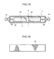
- the coaxial dielectric filter according to the first embodiment is constituted chiefly of, as shown in Figs. 1A and 1B, i) a straight cutoff waveguide 1, ii) two coaxial dielectric resonators (1/2 wavelength type resonators) 21 and 22 disposed coaxially or substantially coaxially and at an interval in the cutoff waveguide 1, iii) an input-side connector 31 fastened to the wall surface on the one-end side in the lengthwise direction of the cutoff waveguide 1, iv) a rod-like input-side antenna 32 whose base end is supported by the input-side connector 31 and whose leading end stands close, or inserted, to the inside of an input-side inner conductor of the coaxial dielectric resonator 21 disposed on the input side, v) an output-side connector 41 fastened to the wall surface on the other-end side in the lengthwise direction of the cutoff waveguide 1, and vi) a rod-like output-side antenna 42 whose base end is supported by the output-side connector 41 and whose leading
- the cutoff waveguide 1 is, as shown in Figs. 1A and 1B, constituted of a metal casing 11 made of aluminum which is provided with substantially a rectangular holding part 10, and a metal cover 12 made of aluminum which closes the open side of the metal casing 11.
- materials constituting the cutoff waveguide 1 are, in addition to aluminum, exemplified by alloys thereof, brass, and gold-plated plastic materials.
- the coaxial dielectric resonators 21 and 22 are, as shown in Fig. 1A, each constituted chiefly of i) a tubular main body having a cross-sectionally quadrangular shape in appearance and having a cross-sectionally circular shape at its cavity, formed of a lead titanate type or barium titanate type dielectric material, and ii) silver conductive films provided on the periphery and inner wall of the tubular main body.
- the adjacent-side ends of these resonators 21 and 22 are each cut obliquely to form a slope which is inclined with respect to the cutoff waveguide 1 in its cross section ⁇ perpendicular to the lengthwise direction. Also, each slope is set to have an oblique angle ⁇ of 60 degrees with respect to the lengthwise direction of the cutoff waveguide 1.
- this coaxial dielectric filter To assemble this coaxial dielectric filter, first the input-side antenna 32 is attached to the metal casing 11 by means of the input-side connector 31, and the input-side coaxial dielectric resonator (1/2 wavelength type resonator) 21 is disposed in the casing while adjusting its distance to the input-side antenna 32. Then, the coaxial dielectric resonator 21 is fastened to the holding part 10 through an appropriate adhesive.
- the input-side antenna 32 is attached to the metal casing 11 by means of the input-side connector 31, and the input-side coaxial dielectric resonator (1/2 wavelength type resonator) 21 is disposed in the casing while adjusting its distance to the input-side antenna 32. Then, the coaxial dielectric resonator 21 is fastened to the holding part 10 through an appropriate adhesive.
- the output-side coaxial dielectric resonator 22 is arranged adjacently to the coaxial dielectric resonator 21 thus fastened, and the distance between the coaxial dielectric resonators 21 and 22 is adjusted to adjust the degree of electrical coupling between them.
- the distance between the coaxial dielectric resonators 21 and 22 on their adjacent sides can be adjusted not only when the coaxial dielectric resonator 22 provided with the slope is moved in the lengthwise direction of the cutoff waveguide 1 but also when it is moved in the width direction of the cutoff waveguide 1 (see the illustration by chain lines in Fig. 2A). More specifically, the coaxial dielectric resonator 22 provided with the slope is first moved in the lengthwise direction to adjust its position with respect to the coaxial dielectric resonator 21 having been fastened, and thereafter the coaxial dielectric resonator 22 is next moved in the width direction, thus the distance between the coaxial dielectric resonators 21 and 22 can be micro-adjusted.
- the adjustment of the degree of electrical coupling between the coaxial dielectric resonators 21 and 22 can be made simply and also the adjustment precision can be improved.
- the coaxial dielectric resonator 22 since the coaxial dielectric resonator 22 is moved in the width direction, it may deviate positionally a little in the width direction, with respect to the fastened coaxial dielectric resonator 21 (that is, it follows that the coaxial dielectric resonator 22 is disposed not perfectly coaxially with respect to the coaxial dielectric resonator 21). It, however, has been confirmed that such positional deviation may affect filter characteristics only very slightly. It has also been confirmed that any occurrence of spurious signals ascribable to the feature that the adjacent-side ends of the coaxial dielectric resonators 21 and 22 form slopes may cause almost no problem so long as the following condition is fulfilled. That is, when as shown in Figs.
- the coaxial dielectric resonator 22 is fastened to the holding part 10 of the metal casing 11 through an appropriate adhesive, and also the output-side antenna 42 is cut to have a length suited for the adjustment to the coaxial dielectric resonator 22. Thereafter, the output-side antenna 42 is attached to the metal casing 11 by means of the output-side connector 41, thus the coaxial dielectric filter according to the first embodiment is completed.
- the two coaxial dielectric resonators 21 and 22 are used.
- three or more coaxial dielectric resonators may be incorporated to make up the coaxial dielectric filter.
- the adjacent-side end of each coaxial dielectric resonator is set to have an oblique angle ⁇ of 60 degrees. It has been confirmed that the present invention is likewise effective also when the oblique angle ⁇ is set at 45 degrees or 70 degrees.
- only the adjacent-side end of the coaxial dielectric resonator 22 may be made to form the slope and, as the adjacent-side end of the coaxial dielectric resonator 21, one having a vertical surface as in conventional cases may be used as it is.
- Fig. 3 is a plan view of a modification of the coaxial dielectric filter according to the first embodiment of the present invention, in which the input direction of signals is perpendicular or substantially perpendicular to the lengthwise direction of the cutoff waveguide.
- the input-side end of a coaxial dielectric resonator 21 is cut obliquely to form a slope which is inclined with respect to a cutoff waveguide 1 in its cross section perpendicular to the lengthwise direction.
- an input-side antenna 32 is, on its base-end side, supported on the wall surface of the cutoff waveguide 1 on its side standing parallel to the lengthwise direction of the cutoff waveguide 1 and facing the slope of the coaxial dielectric resonator 21 disposed on the input side.
- the input-side antenna 32 is so supported by means of an input-side connector 31.
- the leading end of the input-side antenna 32 stands close to substantially the center of the slope of the coaxial dielectric resonator 21.
- the input direction of signals in the input-side antenna 32 is perpendicular or substantially perpendicular to the lengthwise direction of the cutoff waveguide 1. Except for this feature, this coaxial dielectric filter is substantially the same as the coaxial dielectric filter shown in Figs. 1A and 1B. Each slope is set to have an oblique angle ⁇ of 60 degrees with respect to the lengthwise direction of the cutoff waveguide 1.
- this coaxial dielectric filter also has the advantage that, compared with conventional coaxial dielectric filters which enable only the adjustment made by moving the resonator in the lengthwise direction, the adjustment of the degree of electrical coupling between the coaxial dielectric resonators 21 and 22 can be made simply and also the adjustment precision can be improved.
- this coaxial dielectric filter has the structure wherein the base end of the input-side antenna 32 is supported on the wall surface of the cutoff waveguide on its lengthwise side facing the slope of the coaxial dielectric resonator 21, by means of the input-side connector 31, the size of the coaxial dielectric filter in its lengthwise direction can be made smaller to enable miniaturization. Also, since the input direction of signals is perpendicular or substantially perpendicular to the lengthwise direction of the cutoff waveguide, this filter has the advantage that the freedom of circuit designing in the package where the coaxial dielectric filter of this type is mounted can be improved greatly.
- the adjacent-side ends of the coaxial dielectric resonators 21 and 22 and the input-side end of the coaxial dielectric resonator 21 disposed on the input side are also each set to have an oblique angle ⁇ of 60 degrees. It has also been confirmed that the present invention is likewise effective also when each oblique angle ⁇ is set at 45 degrees or 70 degrees.
- Figs. 4 and 5 are plan views of additional modifications of the coaxial dielectric filter according to the first embodiment of the present invention, in which the input direction and output direction of signals are perpendicular or substantially perpendicular to the lengthwise direction of the cutoff waveguide.
- the input-side end of a coaxial dielectric resonator 21 and the output-side end of a coaxial dielectric resonator 22 are cut obliquely to form slopes which are inclined with respect to a cutoff waveguide 1 in its cross section perpendicular to the lengthwise direction.
- an input-side antenna 32 and an output-side antenna 42 are, on their base end sides, supported on the wall surface of the cutoff waveguide 1 on its sides standing parallel to the lengthwise direction of the cutoff waveguide 1 and facing the slopes of the coaxial dielectric resonators 21 and 22 disposed on the input side and output side, respectively.
- the antennas 32 and 42 are so supported by means of an input-side connector 31 and an input-side connector 41, respectively.
- the leading ends of the input-side antenna 32 and the output-side antenna 42 stands close to substantially the center of the slopes of the coaxial dielectric resonators 21 and 22, respectively.
- the input direction of signals in the input-side antenna 32 and the output direction of signals on the output-side antenna 42 are each perpendicular or substantially perpendicular to the lengthwise direction of the cutoff waveguide 1.
- this coaxial dielectric filter is substantially the same as the coaxial dielectric filter shown in Figs. 1A and 1B.
- Each slope is set to have an oblique angle ⁇ of 60 degrees with respect to the lengthwise direction of the cutoff waveguide 1.
- this coaxial dielectric filter also has the advantages that the adjustment of the degree of electrical coupling between the coaxial dielectric resonators 21 and 22 can be made simply and also the freedom of circuit designing in the package where the coaxial dielectric filter of this type is mounted can be improved greatly.
- the coaxial dielectric filter shown in Fig. 5 is substantially the same as the coaxial dielectric filter shown in Fig. 4, except that an input-side antenna 32 and an input-side connector 31, and an output-side antenna 42 and an output-side connector 41, are provided on the same-side wall surface of the cutoff waveguide.
- the coaxial dielectric filter according to the second embodiment is constituted chiefly of, as shown in Figs. 6A and 6B, i) a cutoff waveguide 1 having one flexure 10 set at an angle of substantially 90 degrees, ii) two coaxial dielectric resonators (1/2 wavelength type resonators) 21 and 22 disposed coaxially or substantially coaxially and at an interval in the cutoff waveguide 1 on its both sides bordering at the flexure, iii) an input-side connector 31 fastened to the wall surface on the one-end side in the direction of resonator arrangement in the cutoff waveguide 1, iv) a rod-like input-side antenna 32 whose base end is supported by the input-side connector 31 and whose leading end stands close, or inserted, to the inside of an input-side inner conductor of the coaxial dielectric resonator 21 disposed on the input side, v) an output-side connector 41 fastened to the wall surface on the other-end side in the direction of resonator arrangement in the cut
- the cutoff waveguide 1 is, as shown in Figs. 6A and 6B, constituted of i) a metal casing 11 having substantially a U-shape in its cross section and substantially an L-share in its plane, obtained by bending sheet-like duralumin (registered trademark), and ii) a metal cover 12 having substantially an L-shape and made of duralumin, which closes the open side of the metal casing 11.
- materials constituting the cutoff waveguide 1 are, in addition to duralumin, exemplified by brass, and gold-plated plastic materials.
- the coaxial dielectric resonators 21 and 22 are, as shown in Fig. 6A, each constituted chiefly of i) a tubular main body having a cross-sectionally quadrangular shape in appearance and having a cross-sectionally circular shape at its cavity, formed of a lead titanate type or barium titanate type dielectric material, and ii) silver conductive films provided on the periphery and inner wall of the tubular main body.
- the adjacent-side ends of these resonators 21 and 22 are each cut obliquely to form a slope which is in parallel or substantially in parallel to a flexure cross section ⁇ along the line passing the middle or substantially the middle of each of the outer peripheral side and inner peripheral side at the flexure 10 in the cutoff waveguide.
- each slope is set to have an oblique angle ⁇ of 45 degrees with respect to the direction of resonator arrangement in the cutoff waveguide 1.
- this coaxial dielectric filter To assemble this coaxial dielectric filter, first the input-side antenna 32 is attached to the metal casing 11 by means of the input-side connector 31, and the input-side coaxial dielectric resonator (1/2 wavelength type resonator) 21 is dispsosed in the casing on its input side bordered by the flexure 10 while adjusting its distance to the input-side antenna 32. Then, the coaxial dielectric resonator 21 is fastened to the interior of the metal casing 11 through an appropriate adhesive.
- the input-side antenna 32 is attached to the metal casing 11 by means of the input-side connector 31, and the input-side coaxial dielectric resonator (1/2 wavelength type resonator) 21 is dispsosed in the casing on its input side bordered by the flexure 10 while adjusting its distance to the input-side antenna 32. Then, the coaxial dielectric resonator 21 is fastened to the interior of the metal casing 11 through an appropriate adhesive.
- the coaxial dielectric resonator 22 is arranged adjacently to the coaxial dielectric resonator 21 thus fastened and on the output side bordered by the flexure 10, and the distance between the coaxial dielectric resonators 21 and 22 is adjusted to adjust the degree of electrical coupling between them.
- the distance between the coaxial dielectric resonators 21 and 22 on their adjacent sides can be adjusted not only when the coaxial dielectric resonator 22 provided with the slope is moved in the direction of resonator arrangement but also when it is moved in the width direction of the cutoff waveguide 1 (see the illustration by chain lines in Fig. 2A). More specifically, the coaxial dielectric resonator 22 provided with the slope is first moved in the direction of resonator arrangement to adjust its position with respect to the coaxial dielectric resonator 21 having been fastened, and thereafter the coaxial dielectric resonator 22 is next moved in the width direction, thus the distance between the coaxial dielectric resonators 21 and 22 can be micro-adjusted.
- the adjustment of the degree of electrical coupling between the coaxial dielectric resonators 21 and 22 can be made simply and also the adjustment precision can be improved.
- the coaxial dielectric resonator 22 is fastened to the interior of the metal casing 11 through an appropriate adhesive, and also the output-side antenna 42 is cut to have a length suited for the adjustment to the coaxial dielectric resonator 22. Thereafter, the output-side antenna 42 is attached to the metal casing 11 by means of the output-side connector 41, thus the coaxial dielectric filter according to the second embodiment is completed.
- this coaxial dielectric filter has the following advantage: Since the adjacent-side ends of these resonators 21 and 22 are each cut obliquely to form the slope which is in parallel or substantially in parallel to a flexure cross section ⁇ along the line passing the middle or substantially the middle of each of the outer peripheral side and inner peripheral side at the flexure 10 of the cutoff waveguide, the coaxial dielectric resonators 21 and 22 have such a relation that their adjacent-side ends face each other through the flexure cross section ⁇ .
- the electrical coupling between the coaxial dielectric resonators 21 and 22 may hardly weaken even when the flexure is set at a small angle of 90 degrees.
- the degree of electrical coupling can be made well-balanced at three points, i.e., between the coaxial dielectric resonator 21 disposed on the input side and the input-side antenna 32, between the coaxial dielectric resonator 22 disposed on the output side and the output-side antenna 42 and between the two coaxial dielectric resonators 21 and 22, making it possible to make the coaxial dielectric filter of this type have the desired characteristics.
- the cutoff waveguide 1 having the flexure 10 since in this coaxial dielectric filter the cutoff waveguide 1 having the flexure 10 is used, the length itself of the filter can be made smaller. Accordingly, when such a filter is mounted on a device in the state it is integrated in a package together with electronic circuits, the device can be made to have no dead space by disposing component parts such as electronic circuits at the space on the inner peripheral side at the flexure 10 of the cutoff waveguide 1, making it possible to achieve great miniaturization.
- each coaxial dielectric resonator 21 and 22 are used.
- three or more coaxial dielectric resonators may be incorporated to make up the coaxial dielectric filter.
- the adjacent-side end of each coaxial dielectric resonator is set to have an oblique angle ⁇ of 45 degrees correspondingly to the flexure 10 set at an angle of substantially 90 degrees (i.e., the oblique angle ⁇ is set at 45 degrees so as to form the slope which is in parallel or substantially in parallel to the flexure cross section ⁇ along the line passing the middle or substantially the middle of each of the outer peripheral side and inner peripheral side at the flexure 10).
- the oblique angle ⁇ may be so set at any angle as to provide a slope which is in parallel or substantially in parallel to the flexure cross section ⁇ correspondingly to the angle at which the flexure 10 is provided.
- Figs. 7A and 7B are plan views of a modification of the coaxial dielectric filter according to the second embodiment of the present invention, in which the input direction of signals is in parallel or substantially in parallel to the width direction of the cutoff waveguide 1.
- the input-side end of a coaxial dielectric resonator 21 is cut obliquely to form a slope which is inclined with respect to a cutoff waveguide 1 in its cross section ⁇ parallel to the width direction of the cutoff waveguide 1.
- an input-side antenna 32 is, on its base-end side, supported on the wall surface of the cutoff waveguide 1 on its side standing perpendicular to the width direction of the cutoff waveguide 1 and facing the slope of the coaxial dielectric resonator 21 disposed on the input side.
- the input-side antenna 32 is so supported by means of an input-side connector 31.
- the leading end of the input-side antenna 32 stands close to substantially the center of the slope of the coaxial dielectric resonator 21.
- the input direction of signals in the input-side antenna 32 is in parallel or substantially in parallel to the width direction of the cutoff waveguide 1. Except for this feature, this coaxial dielectric filter is substantially the same as the coaxial dielectric filter shown in Figs. 6A and 6B.
- the above slope, having an inclination, is set to have an oblique angle ⁇ ' of 60 degrees with respect to the direction of resonator arrangement.
- this coaxial dielectric filter also has the advantage that, compared with conventional coaxial dielectric filters which enable only the adjustment made by moving the resonator in the direction of resonator arrangement, the adjustment of the degree of electrical coupling between the coaxial dielectric resonators 21 and 22 can be made simply and also the electrical coupling between the coaxial dielectric resonators 21 and 22 may hardly weaken even when the flexure 10 is set at a small angle of 90 degrees. Thus, it becomes possible to make the coaxial dielectric filter have the desired characteristics.
- this coaxial dielectric filter has the structure wherein the base end of the input-side antenna 32 is supported on the wall surface of the cutoff waveguide on its lengthwise side facing the slope of the coaxial dielectric resonator 21, by means of the input-side connector 31, the size of the coaxial dielectric filter in its direction of resonator arrangement can be made smaller to enable further miniaturization. Also, since the input direction of signals is in parallel or substantially in parallel to the width direction of the cutoff waveguide, this filter has the advantage that the freedom of circuit designing in the package where the coaxial dielectric filter of this type is mounted can be improved greatly.
- the above slope, having an inclination is set to have an oblique angle ⁇ ' of 60 degrees. It has also been confirmed that the present invention is likewise effective also when the oblique angle ⁇ ' is set at 45 degrees or 70 degrees.
- Figs. 8A and 8B illustrate a coaxial dielectric filter in which a substantially U-shaped waveguide having two flexures is used and also one coaxial dielectric resonator is disposed in each of an input-side section and an output-side section which stand parallel to each other and an intermediate section connecting these input-side and output-side sections at their one-side ends.
- this coaxial dielectric filter is constituted chiefly of i) a cutoff waveguide 1 having substantially a U-shape in its plane, comprising an input-side section 101 and an output-side section 102 which stand parallel to each other and an intermediate section 103 connecting these input-side and output-side sections at their one-side ends, and having two flexures comprising a first flexure 104 having an angle of substantially 90 degrees, formed by the input-side section 101 and the intermediate section 103, and a second flexure 105 having an angle of substantially 90 degrees, formed by the output-side section 102 and the intermediate section 103, 11) one coaxial dielectric resonator (1/2 wavelength type resonator) 21 disposed in the input-side section 101 of the cutoff waveguide 1, iii) one coaxial dielectric resonator (1/2 wavelength type resonator) 22 disposed in the output-side section 102 of the cutoff waveguide 1, iv) one coaxial dielectric resonator (1/2 wavelength type resonator)
- the cutoff waveguide 1 is, as shown in Figs. 8A and 8B, constituted of a metal casing 11 made of aluminum which is provided with substantially a U-shaped holding part (constituted of the input-side section 101, the output-side section 102 and the intermediate section 103), and a metal cover 12 made of aluminum which closes the open side of the metal casing 11.
- the coaxial dielectric resonators 21, 22 and 23 are, as shown in Fig. 8A, each constituted chiefly of i) a tubular main body having a cross-sectionally quadrangular shape in appearance and having a cross-sectionally circular shape at its cavity, and ii) conductor layers formed of thick-film silver paste, provided on the periphery and inner wall of the tubular main body.
- the adjacent-side ends of the coaxial dielectric resonators 21 and 23 are each cut obliquely to form a slope which is in parallel or substantially in parallel to a first-flexure cross section ⁇ 1 along the line passing the middle or substantially the middle of each of the outer peripheral side and inner peripheral side at the first flexure 104 in the cutoff waveguide.
- each slope is set to have an oblique angle ⁇ of 45 degrees with respect to the direction of resonator arrangement in the cutoff waveguide 1.
- this coaxial dielectric filter also has the advantage that, compared with conventional coaxial dielectric filters which enable only the adjustment made by moving the resonator in the direction of resonator arrangement, the adjustment of the degree of electrical coupling between the coaxial dielectric resonators 21, 22 and 23 can be made simply and also the electrical coupling between the coaxial dielectric resonators 21, 22 and 23 may hardly weaken even when the first flexure 104 and second flexure 105 are set at small angles of 90 degrees. Thus, it becomes possible to make the coaxial dielectric filter have the desired characteristics.
- the cutoff waveguide 1 is constituted of the substantially U-shaped waveguide 1 comprising the input-side and output-side sections 101 and 102 standing parallel to each other and one intermediate section 103 connecting these input-side and output-side sections at their one-side ends, the disposing space can be made small greatly.
- the coaxial dielectric resonators 21 and 22 in the input-side and output-side sections 101 and 102, respectively, have a positional relation parallel to each other, and the input side and output side can be disposed on the same side. Hence, the freedom of circuit designing in the package where the coaxial dielectric filter of this type is mounted can be improved greatly.
- a coaxial dielectric filter comprising a straight cutoff waveguide, at least two coaxial dielectric resonators disposed coaxially or substantially coaxially and at an interval in the cutoff waveguide in its lengthwise direction, a rod-like input-side antenna whose leading end stands close, or inserted, to the inside of an input-side inner conductor of the coaxial dielectric resonator disposed on the input side, and a rod-like output-side antenna whose leading end stands close, or inserted, to the inside of an output-side inner conductor of the coaxial dielectric resonator disposed on the output side.
- This filter is characterized in that an adjacent-side end of at least one of coaxial dielectric resonators adjacent to each other forms a slope which is inclined with respect to the cutoff waveguide in its cross section perpendicular to the lengthwise direction.
- the distance between the coaxial dielectric resonators on their adjacent sides can be adjusted simply not only when the coaxial dielectric resonator provided with the slope is moved in the lengthwise direction of the cutoff waveguide but also when it is moved in the width direction of the cutoff waveguide.
Landscapes
- Physics & Mathematics (AREA)
- Electromagnetism (AREA)
- Control Of Motors That Do Not Use Commutators (AREA)
Claims (6)
- Filtre coaxial diélectrique comprenant :un guide d'onde évanescent droit (1) ;au moins deux résonateurs coaxiaux diélectriques (21, 22) disposés totalement ou essentiellement de façon coaxiale et à un intervalle à l'intérieur du guide d'onde évanescent (1) dans le sens de sa longueur ;une antenne d'entrée en forme de tige (32), dont l'extrémité libre se trouve à proximité ou insérée à l'intérieur d'un conducteur interne à l'entrée du résonateur coaxial diélectrique (21) installé côté entrée ; etune antenne de sortie en forme de tige (42), dont l'extrémité libre se trouve à proximité ou insérée à l'intérieur d'un conducteur interne à la sortie du résonateur coaxial diélectrique (22) installé côté sortie ;caractérisé en ce queune extrémité contiguë d'au moins un des résonateurs coaxiaux diélectriques (21, 22) adjacents l'un à l'autre possède une inclinaison (θ) par rapport à la coupe transversale (α) du guide d'onde évanescent (1) perpendiculaire au sens de sa longueur.
- Filtre coaxial diélectrique selon la revendication 1, dans lequel
au moins l'une des extrémités, l'une se trouvant à l'entrée du résonateur coaxial diélectrique (21) installé côté entrée et l'autre se trouvant à la sortie du résonateur coaxial diélectrique (22) installé côté sortie, doit posséder l'inclinaison (θ) par rapport à la coupe transversale (α) du guide d'onde évanescent (1) perpendiculaire au sens de sa longueur ;
par sa/leur base, l'/les antenne(s) d'entrée et/ou de sortie (32, 42) est/sont montée(s), soit directement, soit au moyen d'un connecteur côté entrée et/ou côté sortie (31, 41), sur la/les paroi(s) du guide d'onde évanescent (1) sur son/ses côté(s) parallèle(s) au sens de la longueur du guide d'onde évanescent (1) et face à l'inclinaison (θ) du/des résonateur(s) coaxial(aux) diélectrique(s) (21, 22) installé(s) côté entrée et/ou côté sortie de celui-ci ; et
l'extrémité libre de l'/des antenne(s) d'entrée et/ou de sortie (32, 42) est disposée de façon à être sensiblement à proximité du centre de l'inclinaison (θ) du/des résonateur(s) coaxial(aux) diélectrique(s) (21, 22) installé(s) côté entrée et/ou sortie, de telle sorte que la direction de l'entrée et/ou de la sortie des signaux est totalement ou essentiellement perpendiculaire au sens de la longueur du guide d'onde évanescent (1). - Filtre coaxial diélectrique comprenant :un guide d'onde évanescent (1) ayant au moins une courbure (10) ;au moins deux résonateurs diélectriques coaxiaux (21, 22) disposés totalement ou essentiellement de façon coaxiale et à un intervalle à l'intérieur du guide d'onde évanescent (1), de chaque côté de la courbure (10) ;une antenne d'entrée en forme de tige (32), dont l'extrémité libre se trouve à proximité ou insérée à l'intérieur d'un conducteur interne à l'entrée du résonateur coaxial diélectrique (21) installé côté entrée ; etune antenne de sortie en forme de tige (42), dont l'extrémité libre se trouve à proximité ou insérée à l'intérieur d'un conducteur interne à la sortie du résonateur coaxial diélectrique (22) installé côté sortie ;caractérisé en ce queles extrémités adjacentes d'une paire de résonateurs coaxiaux diélectriques (21, 22), contigus entre eux le long de la courbure (10), possèdent chacune une inclinaison (θ) en parallèle ou essentiellement en parallèle d'une coupe transversale (α) de la courbure (10) le long de la ligne passant totalement ou essentiellement au milieu de chacun des côtés périphériques interne et externe à la courbure (10) dans le guide d'onde évanescent (1).
- Filtre coaxial diélectrique selon la revendication 3, dans lequel
au moins l'une des extrémités, l'une se trouvant à l'entrée du résonateur coaxial diélectrique (21) installé côté entrée et l'autre se trouvant à la sortie du résonateur coaxial diélectrique (22) installé côté sortie, doit posséder une autre inclinaison (θ') par rapport à la coupe transversale (β) du guide d'onde évanescent (1) parallèle au sens de la largueur du guide d'onde évanescent (1);
par sa/leur base, l'/les antenne(s) d'entrée et/ou de sortie (32, 42) est/sont montée(s), soit directement, soit au moyen d'un connecteur côté entrée et/ou côté sortie (31, 41), sur la/les paroi(s) du guide d'onde évanescent (1) sur son/ses côté(s) perpendiculaire(s) au sens de la largeur du guide d'onde évanescent (1) et face à l'inclinaison (θ') du/des résonateur(s) coaxial(aux) diélectrique(s) (21, 22) installé(s) côté entrée et/ou côté sortie de celui-ci ; et
l'extrémité libre de 1'/des antenne(s) d'entrée et/ou de sortie (32, 42) est disposée de façon à être sensiblement à proximité du centre de l'angle (θ') du/des résonateur(s) coaxial(aux) diélectrique(s) (21, 22) installé(s) côté entrée et/ou sortie, de telle sorte que la direction de l'entrée et/ou de la sortie des signaux est totalement ou essentiellement parallèle au sens de la largeur du guide d'onde évanescent (1). - Filtre coaxial diélectrique selon la revendication 3, dans lequel
ledit guide d'onde évanescent (1) consiste en un guide d'onde essentiellement en forme de U comprenant une section d'entrée (101) et une section de sortie (102), parallèles l'une à l'autre, et une section intermédiaire (103) qui relie ces sections d'entrée et de sortie (101, 102) par l'une de leurs extrémités ;
un résonateur coaxial diélectrique (21, 22, 23) est disposé dans chacune des sections d'entrée, de sortie et section intermédiaire du guide d'onde essentiellement en forme de U (1) ;
les extrémités adjacentes du résonateur coaxial diélectrique (21) installé dans la section d'entrée (101) et du résonateur coaxial diélectrique (23) installé dans la section intermédiaire (103) possèdent chacune une inclinaison (θ) en parallèle ou essentiellement en parallèle de la coupe transversale d'une première courbure (104) le long de la ligne (α1) passant totalement ou essentiellement au milieu de chacun des côtés périphériques externe et interne à la première courbure (104) dans le guide d'onde évanescent (1) ; et
les extrémités adjacentes du résonateur coaxial diélectrique (23) installé dans la section intermédiaire (103) et du résonateur coaxial diélectrique (22) installé dans la section de sortie (102) possèdent chacune une inclinaison (θ) en parallèle ou essentiellement en parallèle de la section transversale d'une seconde courbure (105) le long de la ligne (α2) passant totalement ou essentiellement au milieu de chacun des côtés périphériques externe et interne à la seconde courbure (105) dans le guide d'onde évanescent (1). - Filtre coaxial diélectrique selon l'une quelconque des revendications 1 à 5, dans lequel
ledit résonateur coaxial diélectrique (21, 22, 23) est un résonateur coaxial diélectrique à ½ longueur d'onde comprenant un corps principal tubulaire (a1) fourni avec un conducteur externe (a2) et un conducteur interne (a3) respectivement sur sa paroi périphérique et sur sa paroi interne.
Applications Claiming Priority (4)
| Application Number | Priority Date | Filing Date | Title |
|---|---|---|---|
| JP5897098A JPH11243302A (ja) | 1998-02-24 | 1998-02-24 | 同軸形誘電体フィルタ |
| JP5896998 | 1998-02-24 | ||
| JP5896998A JPH11243301A (ja) | 1998-02-24 | 1998-02-24 | 同軸形誘電体フィルタ |
| JP5897098 | 1998-02-24 |
Publications (2)
| Publication Number | Publication Date |
|---|---|
| EP0938152A1 EP0938152A1 (fr) | 1999-08-25 |
| EP0938152B1 true EP0938152B1 (fr) | 2006-05-03 |
Family
ID=26399984
Family Applications (1)
| Application Number | Title | Priority Date | Filing Date |
|---|---|---|---|
| EP99103471A Expired - Lifetime EP0938152B1 (fr) | 1998-02-24 | 1999-02-23 | Filtre coaxial diélectrique |
Country Status (4)
| Country | Link |
|---|---|
| US (1) | US6097270A (fr) |
| EP (1) | EP0938152B1 (fr) |
| CA (1) | CA2262127C (fr) |
| DE (1) | DE69931095T2 (fr) |
Families Citing this family (4)
| Publication number | Priority date | Publication date | Assignee | Title |
|---|---|---|---|---|
| US7009469B2 (en) * | 2002-06-28 | 2006-03-07 | Harris Corporation | Compact waveguide filter and method |
| US10903811B2 (en) * | 2017-08-18 | 2021-01-26 | Avx Corporation | Coaxial RF filter with discoidal capacitor |
| US11532862B1 (en) * | 2021-06-29 | 2022-12-20 | Meta Platforms, Inc. | Housing structure for maintaining alignment between ceramic sections of a waveguide filter |
| CN114497940B (zh) * | 2022-02-17 | 2025-10-17 | 浙江嘉科电子有限公司 | 一种机载免调试型大功率交叉耦合腔体滤波器 |
Family Cites Families (5)
| Publication number | Priority date | Publication date | Assignee | Title |
|---|---|---|---|---|
| US3939443A (en) * | 1972-01-07 | 1976-02-17 | Finommechanikai Vallalat | Frequency-selective coupling for high-frequency electromagnetic waves |
| GB1568255A (en) * | 1976-02-10 | 1980-05-29 | Murata Manufacturing Co | Electrical filter |
| US4223287A (en) * | 1977-02-14 | 1980-09-16 | Murata Manufacturing Co., Ltd. | Electrical filter employing transverse electromagnetic mode coaxial resonators |
| JP2821567B2 (ja) * | 1993-02-26 | 1998-11-05 | 五郎 菅原 | 高周波信号伝送装置 |
| JP3022202B2 (ja) * | 1994-09-16 | 2000-03-15 | 住友金属鉱山株式会社 | 同軸形誘電体フィルタ |
-
1999
- 1999-02-16 CA CA002262127A patent/CA2262127C/fr not_active Expired - Fee Related
- 1999-02-22 US US09/253,712 patent/US6097270A/en not_active Expired - Fee Related
- 1999-02-23 DE DE69931095T patent/DE69931095T2/de not_active Expired - Fee Related
- 1999-02-23 EP EP99103471A patent/EP0938152B1/fr not_active Expired - Lifetime
Also Published As
| Publication number | Publication date |
|---|---|
| US6097270A (en) | 2000-08-01 |
| DE69931095D1 (de) | 2006-06-08 |
| CA2262127C (fr) | 2007-10-30 |
| DE69931095T2 (de) | 2006-10-19 |
| CA2262127A1 (fr) | 1999-08-24 |
| EP0938152A1 (fr) | 1999-08-25 |
Similar Documents
| Publication | Publication Date | Title |
|---|---|---|
| US4963844A (en) | Dielectric waveguide-type filter | |
| US3840828A (en) | Temperature-stable dielectric resonator filters for stripline | |
| US6031433A (en) | Dielectric waveguide | |
| US6184759B1 (en) | Dielectric filter having inductive coupling windows between resonators, and transceiver using the dielectric filter | |
| JPH0738307A (ja) | フィルタ及びその形成方法 | |
| JPH07105644B2 (ja) | 有極型誘電体フィルタ | |
| JP2949250B2 (ja) | チップ型フィルタ | |
| EP0938152B1 (fr) | Filtre coaxial diélectrique | |
| JPH0211163B2 (fr) | ||
| EP1079457A2 (fr) | Dispositif à résonance diélectrique, filtre diélectrique, dispositif filtre diélectrique composé, duplexeur diélectrique et appareil de communication | |
| EP0738020B1 (fr) | Appareil a resonateur dielectrique a double mode tm dote d'une fenetre de couplage de champ electromagnetique, et appareil a filtre passe-bande dote de l'appareil a resonateur dielectrique | |
| EP0746052B1 (fr) | Filtre diélectrique | |
| JPH0255402A (ja) | 誘電体フィルタ | |
| JP2765396B2 (ja) | ストリップ線路フィルタ及びマイクロストリップ線路フィルタ | |
| JP3626909B2 (ja) | 誘電体フィルタ及びその製造方法 | |
| JPH0370402B2 (fr) | ||
| US5546059A (en) | Dielectric filter having a non-conductive region in each resonator hole | |
| JPH06112704A (ja) | 誘電体フィルタ | |
| JP3306137B2 (ja) | 誘電体フィルタの共振周波数調整方法 | |
| JP2567368B2 (ja) | 誘電体共振器およびフィルタ | |
| JPH05191103A (ja) | 積層型誘電体フィルタ | |
| JP3469476B2 (ja) | 誘電体フィルタ | |
| JPH11243301A (ja) | 同軸形誘電体フィルタ | |
| JPH11243302A (ja) | 同軸形誘電体フィルタ | |
| JP2525311B2 (ja) | 誘電体共振器及び誘電体フィルタ |
Legal Events
| Date | Code | Title | Description |
|---|---|---|---|
| PUAI | Public reference made under article 153(3) epc to a published international application that has entered the european phase |
Free format text: ORIGINAL CODE: 0009012 |
|
| AK | Designated contracting states |
Kind code of ref document: A1 Designated state(s): DE FR GB IT |
|
| AX | Request for extension of the european patent |
Free format text: AL;LT;LV;MK;RO;SI |
|
| 17P | Request for examination filed |
Effective date: 20000125 |
|
| AKX | Designation fees paid |
Free format text: DE FR GB IT |
|
| 17Q | First examination report despatched |
Effective date: 20040916 |
|
| GRAP | Despatch of communication of intention to grant a patent |
Free format text: ORIGINAL CODE: EPIDOSNIGR1 |
|
| GRAS | Grant fee paid |
Free format text: ORIGINAL CODE: EPIDOSNIGR3 |
|
| GRAA | (expected) grant |
Free format text: ORIGINAL CODE: 0009210 |
|
| AK | Designated contracting states |
Kind code of ref document: B1 Designated state(s): DE FR GB IT |
|
| PG25 | Lapsed in a contracting state [announced via postgrant information from national office to epo] |
Ref country code: IT Free format text: LAPSE BECAUSE OF FAILURE TO SUBMIT A TRANSLATION OF THE DESCRIPTION OR TO PAY THE FEE WITHIN THE PRE;WARNING: LAPSES OF ITALIAN PATENTS WITH EFFECTIVE DATE BEFORE 2007 MAY HAVE OCCURRED AT ANY TIME BEFORE 2007. THE CORRECT EFFECTIVE DATE MAY BE DIFFERENT FROM THE ONE RECORDED.SCRIBED TIME-LIMIT Effective date: 20060503 |
|
| REG | Reference to a national code |
Ref country code: GB Ref legal event code: FG4D |
|
| REF | Corresponds to: |
Ref document number: 69931095 Country of ref document: DE Date of ref document: 20060608 Kind code of ref document: P |
|
| ET | Fr: translation filed | ||
| PLBE | No opposition filed within time limit |
Free format text: ORIGINAL CODE: 0009261 |
|
| STAA | Information on the status of an ep patent application or granted ep patent |
Free format text: STATUS: NO OPPOSITION FILED WITHIN TIME LIMIT |
|
| 26N | No opposition filed |
Effective date: 20070206 |
|
| PGFP | Annual fee paid to national office [announced via postgrant information from national office to epo] |
Ref country code: DE Payment date: 20090219 Year of fee payment: 11 |
|
| PGFP | Annual fee paid to national office [announced via postgrant information from national office to epo] |
Ref country code: GB Payment date: 20090217 Year of fee payment: 11 |
|
| PGFP | Annual fee paid to national office [announced via postgrant information from national office to epo] |
Ref country code: IT Payment date: 20090217 Year of fee payment: 11 |
|
| PGFP | Annual fee paid to national office [announced via postgrant information from national office to epo] |
Ref country code: FR Payment date: 20090213 Year of fee payment: 11 |
|
| GBPC | Gb: european patent ceased through non-payment of renewal fee |
Effective date: 20100223 |
|
| REG | Reference to a national code |
Ref country code: FR Ref legal event code: ST Effective date: 20101029 |
|
| PG25 | Lapsed in a contracting state [announced via postgrant information from national office to epo] |
Ref country code: FR Free format text: LAPSE BECAUSE OF NON-PAYMENT OF DUE FEES Effective date: 20100301 |
|
| PG25 | Lapsed in a contracting state [announced via postgrant information from national office to epo] |
Ref country code: DE Free format text: LAPSE BECAUSE OF NON-PAYMENT OF DUE FEES Effective date: 20100901 |
|
| PG25 | Lapsed in a contracting state [announced via postgrant information from national office to epo] |
Ref country code: GB Free format text: LAPSE BECAUSE OF NON-PAYMENT OF DUE FEES Effective date: 20100223 Ref country code: IT Free format text: LAPSE BECAUSE OF NON-PAYMENT OF DUE FEES Effective date: 20100223 |