EP0938231B1 - Procédé et arrangement pour l'enregistrement et l'exploitation d'images d'un objet - Google Patents
Procédé et arrangement pour l'enregistrement et l'exploitation d'images d'un objet Download PDFInfo
- Publication number
- EP0938231B1 EP0938231B1 EP99890036A EP99890036A EP0938231B1 EP 0938231 B1 EP0938231 B1 EP 0938231B1 EP 99890036 A EP99890036 A EP 99890036A EP 99890036 A EP99890036 A EP 99890036A EP 0938231 B1 EP0938231 B1 EP 0938231B1
- Authority
- EP
- European Patent Office
- Prior art keywords
- image
- images
- points
- image signals
- recorded
- Prior art date
- Legal status (The legal status is an assumption and is not a legal conclusion. Google has not performed a legal analysis and makes no representation as to the accuracy of the status listed.)
- Expired - Lifetime
Links
- 238000000034 method Methods 0.000 title claims description 25
- 230000003595 spectral effect Effects 0.000 claims description 29
- 230000009466 transformation Effects 0.000 claims description 29
- 238000011156 evaluation Methods 0.000 claims description 27
- 230000009467 reduction Effects 0.000 claims description 17
- 238000001228 spectrum Methods 0.000 claims description 6
- 238000001454 recorded image Methods 0.000 claims description 4
- 238000005286 illumination Methods 0.000 claims description 3
- 238000012545 processing Methods 0.000 claims description 2
- 238000001914 filtration Methods 0.000 claims 3
- 230000015572 biosynthetic process Effects 0.000 claims 2
- 235000019646 color tone Nutrition 0.000 claims 2
- 238000003384 imaging method Methods 0.000 claims 1
- 238000000844 transformation Methods 0.000 claims 1
- 238000005259 measurement Methods 0.000 description 4
- 230000008901 benefit Effects 0.000 description 2
- 230000005540 biological transmission Effects 0.000 description 2
- 238000013459 approach Methods 0.000 description 1
- 230000009286 beneficial effect Effects 0.000 description 1
- 230000008859 change Effects 0.000 description 1
- 235000019504 cigarettes Nutrition 0.000 description 1
- 230000002596 correlated effect Effects 0.000 description 1
- 230000000875 corresponding effect Effects 0.000 description 1
- 239000005022 packaging material Substances 0.000 description 1
- 238000002360 preparation method Methods 0.000 description 1
- 230000008569 process Effects 0.000 description 1
- 238000003908 quality control method Methods 0.000 description 1
- 239000002689 soil Substances 0.000 description 1
- 238000012546 transfer Methods 0.000 description 1
Images
Classifications
-
- H—ELECTRICITY
- H04—ELECTRIC COMMUNICATION TECHNIQUE
- H04N—PICTORIAL COMMUNICATION, e.g. TELEVISION
- H04N25/00—Circuitry of solid-state image sensors [SSIS]; Control thereof
Definitions
- the invention relates to a method according to the preamble of patent claim 1. Furthermore, the invention relates to an arrangement, in particular for carrying it out Method according to the preamble of claim 11.
- an intensity image of high resolution and further at least one color characteristic image with low resolution is provided.
- more than one color characteristic image can be recorded and available be put; it turned out that it was sufficient to use only one high-resolution intensity image for to have the evaluation available, since we know from experience that deviations in the color can be perceived with lower resolution than deviations in the intensity.
- the number of cameras with which the pictures can be taken can be added as needed to increase the diversity of the Evaluation options can be selected.
- the filters are in front of the camera lenses arranged and easily replaceable. The adjustment of the cameras is done with a Filter exchange not changed.
- An arrangement according to claim 16 is advantageous, with which the mutual Assignment of identical, imaged on the sensor chips of the individual cameras Item points can be made.
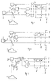
- an object 1 with a number of Cameras 2,2 'and 2 each have at least one picture taken.
- the cameras are concerned deal with grayscale cameras with common sensor chips, with which one area of the Item 1 takes a picture. It does not necessarily have to be exactly act the same area of the object, but the individual recorded Images should include at least one common subject area that is common to all Pictures appear; this common subject area can be evaluated be subjected.
- the number of cameras depends on the desired number of cameras Evaluation provided, recorded in different wavelength ranges Images selected. Usually images of the subject area are divided into two or more different wavelength or spectral ranges are recorded or one Grayscale image, comprising the entire color spectrum, and at least one additional image in a predetermined wavelength or spectral range. advantageously, a black-and-white or grayscale image and a color image in a certain Wavelength or spectral range recorded.
- the main aim of the invention is providing an intensity image I with high resolution and the creation of at least one color characteristic image in reduced resolution, in particular one Hue image B and / or a saturation image S. For taking the intensity image an arrangement of a filter is not, as long as it is a grayscale image necessary.
- the cameras 2,2 'or their sensor chips are in each case one or a common reduction unit 6 is connected downstream.
- Such Reduction unit 6 could, for example, only the image signal of every second pixel in Feed the evaluation to the horizontal and vertical direction of the sensor chip, whereby the number of image signals that can be evaluated is reduced to a quarter.
- the image signals of the individual images subjected to an electronic position transformation in the positioning unit 7.
- the position of the subject points of the images, which are associated with a reduced number of image signals are present at the position of the object points of the Adjusted intensity image, which is available with high resolution.
- the image signals of the intensity image are combined in one Reduction unit 6 'also reduced and with the reduced image signals of the others Images linked to color characteristic images; in particular takes place in the Transformation unit 8 links the reduced image signals to hue images B and / or saturation images S.
- Memory for temporary storage of the reduced number of image signals further images and memory in the evaluation unit 5 for storing the intensity image I, the hue image B and the saturation image S are not shown.
- a positioning unit 7 is not present because in principle it is possible to adjust the cameras 2, 2 'and 2 "in such a way that the sensor chips the individual cameras are clearly aligned to the same image section; a such positioning is mechanically possible, but expensive; one is preferable electronic positioning unit 7.
- Fig. 3 shows an arrangement in which images of the object 1 with only one single camera 2 "can be recorded.
- the successively recorded images of the same subject area or overlapping subject areas become Times recorded in which filters 3,3 ', 3 "of different wavelengths or. spectral transmission are in the light path. In this way, images of the Obtained object range in different wavelength or spectral ranges.
- an illumination device 9 indicated in FIG. 3 could also be used be provided that the object 1 by itself in front of the lighting device 9 located filter 3,3 ', 3 "illuminated with light of different wavelength ranges, so that also in this way with the camera 2 "images in different wavelengths or Spectral ranges can be recorded one after the other.
- this image is in particular a black and white or gray value image recorded and there is no filter in the light path between the object 1 and the Camera 2 "arranged or an illumination of the object 1 is with white light performed.
- the image signals of the other images that are used with low or reduced resolution Should be available, are passed through the reducing units 6 and the Linking or transformation unit 8 supplied in the according to a predetermined Algorithm a link to the reduced image signals of the intensity image Hue and / or saturation images.
- the two reducing units 6, the switching unit 10 are connected downstream, and the reduction of the image signals in the reducing unit 6 'in the linking unit 8 take place. It would only be necessary to ensure that those of the Camera 2 "delivered image signals depending on their belonging to an intensity image or to one with a certain wavelength or in a certain spectral range recorded further image saved separately and if necessary after each other Assignment in a positioning unit 7 according to its affiliation with and linked to the same item point.
- An electronic positioning unit 7 is not required in the case of FIG. 3 if the camera 2 "can take pictures of one and the same subject area, i.e. when the object 1 is at rest relative to the camera 2 ".
- the use of electronic positioning devices 7 is advantageous if the images are recorded with several cameras 2, 2 ', 2 "and / or if, as it is e.g. 3 could be the case, the object 1 during the Taking the pictures moved relative to the taking camera (s); in these cases Care must be taken to ensure that an evaluation is only made for the subject area at most or only for that area of the recording field that is in each of the Evaluation of the images used is included.
- filters 3, 3 ' which are arranged directly in front of the cameras 2, 2', consists in the easy interchangeability of these filters and the fact that one Replacing the filter does not change the position of the camera.
- a division of the light rays gives the advantage that in front of the object of the camera commercially available standard filters, e.g. high quality selective interference filters, can be arranged interchangeably. Changing the filter is mechanical Filter changer possible and standard lenses can be used for the cameras.
- a position calibration is also possible to a fraction of Compensate pixel positions by an image transformation and interpolation in the Sub-pixel area.
- the image signals of the intensity image must also be included, the image signals of the intensity image are also reduced for the transformation and the reduced, i.e. those electronically reduced or those using lower Resolving sensor chips in fewer numbers, image signals of the recorded Images linked in the transformation unit 8.
- the procedure according to the invention is also suitable for TDI cameras, even if these cameras are operated at different clock rates. In principle it would be necessary that all TDI cameras with the same image scale and with the same Clock rate work; however, this can be done by the electronic positioning unit 8 be balanced and it is only important to ensure that the three TDI cameras are on are aligned with the same recording field.
- Images of object 1 are usually recorded with three cameras; in principle, the procedure according to the invention is also with only two or with more than three Cameras that take pictures of different wavelengths or different spectral ranges record, realizable.
- a black and white or gray-scale image in particular as an intensity image with high resolution, and only one color image, e.g. an ultraviolet or infrared image, because we know from experience that deviations in color are lower resolution can be perceived than deviations in brightness (Intensity).
- the procedure according to the invention is particularly suitable for Quality control of printing units, e.g. Securities, banknotes, checks, check cards, Stamps and postage stamps or packaging material, e.g. cigarette, Can lid etc.
- printing units e.g. Securities, banknotes, checks, check cards, Stamps and postage stamps or packaging material, e.g. cigarette, Can lid etc.
- the intensity image is high resolution
- the second image is a color image of a specific wavelength or spectral range, this image is shown in low resolution.
- the high resolution image advantageously comprises the entire color spectrum, i.e. it is a gray scale image; however, it could also be provided that the high-resolution Image depending on a special application for increasing contrast also recorded a certain selective color spectrum.
- Another purpose of the invention can be identification, classification and Measurement of objects, e.g. in aerial photography, or an analysis of medical Be preparations.
- Multispectral recordings i.e. Recordings in two or more spectral ranges is usually done for different purposes Image resolution required.
- For a classification of objects in aerial photography e.g. with different types of soil plantings, pictures are of different wavelengths or in different spectral ranges, possibly also in the infrared.
- On the other hand requires the determination of boundaries or the measurement of positions of distinctive Dots a high resolution image, e.g. a grayscale image or possibly also a certain color selective image.
- One and the same reducing unit can be used for all those in a row Images are provided and the reduced image signals are before they are linked cached or saved. Even the reduced image signals of the intensity image, the can advantageously be recorded after the further images, can be temporarily stored become.
- the further images taken first are advantageously stored, which are linked to the intensity image recorded later.
- the object record directly with the camera also possible for image transmission and Light path division between the object 1 and the cameras 2, 2 ', 2 "used Light guides are used, 1 images of the same area of the object record and direct to the cameras 2, 2 ', 2 "used, with between the Camera-side end of at least one of the light guides and the lens of the associated one Camera at least one, possibly interchangeable, for a given one Wavelength or spectral range transmissive color filter 3, 3 'is arranged.
Landscapes
- Engineering & Computer Science (AREA)
- Multimedia (AREA)
- Signal Processing (AREA)
- Color Television Image Signal Generators (AREA)
- Image Input (AREA)
- Studio Devices (AREA)
Claims (17)
- Procédé pour l'enregistrement et l'exploitation d'images d'un objet, dans lequel les images au moins de zones de l'objet se chevauchant, ou de préférence d'une même zone de l'objet, sont enregistrées avec au moins une caméra à niveaux de gris et mises à disposition en vue de leur exploitation de préférence après qu'une transformation de l'espace chromatique a été effectuée, caractérisé en ce que :les images sont enregistrées à des longueur d'ondes ou dans des domaines spectraux différents,au moins une image est enregistrée avec une résolution élevée et les signaux d'image dérivés de cette image sont mis à disposition en vue de leur exploitation sous la forme d'une image d'intensité à haute résolution,au moins une autre image est enregistrée avec une résolution moindre ou bien les signaux d'image d'au moins une autre image sont soumis à une réduction,les signaux d'image de l'image d'intensité sont mis à disposition également avec une étendue réduite,les signaux d'image réduits de l'image d'intensité et les signaux d'image réduits ou les signaux d'images à résolution moindre de la ou lesdites autres images sont chaínés par une transformation, de préférence une transformation de l'espace chromatique, et transformés ou assemblés en au moins une image de caractéristique chromatique, de préférence une image de chrominance et/ou une image de saturation, de plus faible résolution, etla ou lesdites images de caractéristique chromatique sont mises à disposition en plus de l'image d'intensité en vue de son retraitement, de son exploitation et/ou de son stockage.
- Procédé selon la revendication 1, caractérisé en ce que les différentes images de l'objet, de préférence se suivant l'une derrière l'autre ou l'une après l'autre, sont enregistrées avec la même caméra à niveaux de gris, ou bien en ce que des images de l'objet sont enregistrées avec au moins deux, de préférence trois, caméras à niveaux de gris, une image de l'objet étant enregistrée avec chacune des caméras à niveaux de gris, de préférence en même temps, à une longueur d'onde ou dans un domaine spectral différent.
- Procédé selon la revendication 1 ou la revendication 2, caractérisé en ce que, pour les différents enregistrements, la lumière venant de l'objet est filtrée différemment en ce qui concerne sa longueur d'onde et/ou son domaine spectral, ou bien en ce que, pour les différents enregistrements, l'objet est éclairé respectivement avec de la lumière de longueur d'onde ou de domaine spectral différent.
- Procédé selon la revendication 2, caractérisé en ce que, pour l'enregistrement d'images à des longueurs d'onde ou dans des domaines spectraux différents, les faisceaux lumineux venant de l'objet sont divisés en chemins optiques et, dans tous les chemins optiques ou dans tous sauf un, on effectue un filtrage, ledit filtrage étant différent dans chaque chemin optique, et en ce que l'on dispose à l'extrémité de chaque chemin optique une caméra au moyen de laquelle les images sont enregistrées à des longueurs d'onde ou dans des domaines spectraux différents, le filtrage étant, le cas échéant, effectué après la division des faisceaux lumineux en différents chemins optiques et avant que les faisceaux lumineux viennent frapper l'objectif de la caméra concernée.
- Procédé selon l'une des revendications 1 à 4, caractérisé en ce que les signaux d'image réduits, au moins ceux des autres images, font l'objet d'un stockage intermédiaire et/ou en ce que les signaux d'image réduits des autres images sont chaínés avec les signaux d'image réduits de l'image d'intensité enregistrée après les autres images.
- Procédé selon l'une des revendications 1 à 5, caractérisé en ce que les signaux d'image des autres images sont réduits en effectuant un moyennage des signaux d'image obtenus à partir d'au moins deux points d'image de préférence adjacents de la puce de capteur, ou bien en ce que seuls des signaux d'image d'un nombre réduit de points d'image de la puce de capteur sont dérivés et/ou en ce que, pour l'enregistrement d'autres images avec un nombre réduit de signaux d'image, on utilise des caméras avec des puces de capteurs qui, comparées à la puce de capteur de la caméra avec laquelle l'image d'intensité à haute résolution a été enregistrée, possèdent une puce de capteur qui présente un plus petit nombre de points d'image, de préférence un quart des points d'image.
- Procédé selon l'une des revendications 1 à 6, caractérisé en ce que, lors de la réduction, les signaux d'image ou les points d'image sont réduits à environ 25% par rapport aux signaux d'image ou points d'image disponibles ou exploitables pour l'enregistrement de l'image d'intensité.
- Procédé selon l'une des revendications 1 à 7, caractérisé en ce que les signaux d'image des autres images et les signaux d'image de l'image d'intensité sont réduits suivant le même algorithme prédéfini et/ou en ce que, pour l'image d'intensité, une image en noir et blanc ou une image en niveaux de gris englobant la totalité du spectre chromatique est enregistrée et mise à disposition avec une haute définition.
- Procédé selon l'une des revendications 1 à 8, caractérisé en ce que les signaux d'image réduits des autres images et de l'image d'intensité sont chaínés pour obtenir les images de caractéristique chromatique par formation de quotient ou de différence, en particulier par formation d'une différence pondérée.
- Procédé selon l'une des revendications 1 à 9, caractérisé en ce que :les caméras et/ou les puces de capteurs des caméras sont ajustées mécaniquement par rapport à l'objet de façon que des points identiques de l'objet soient affectés aux mêmes points d'image sur les puces de capteurs des différentes caméras, et/oules points de l'objet formés sur les puces de capteurs des différentes caméras sont affectés les uns aux autres en fonction de la position en affectant aux mêmes points de l'objet des points d'image mutuellement correspondants ou identiques sur les différentes puces de capteurs, et/oulors d'une reproduction des mêmes points de l'objet sur des points d'image positionnés de manière différente sur les puces de capteurs des différentes caméras, une affectation des points de l'objet et des signaux de points d'image issus des mêmes points de l'objet est effectuée avec une transformation de position géométrique électronique, et/oula position des points de l'objet reproduits des autres images disponibles avec des signaux d'image réduits est adaptée électroniquement à la position des points de l'objet reproduits pour enregistrer l'image d'intensité, et/oula transformation de position électronique des points de l'objet ou des signaux d'image des autres images se fait après réduction des signaux d'image ou bien avec des signaux d'image de résolution moindre, une interpolation électronique au niveau du sous-pixel étant le cas échéant effectuée dans le cas de transformations de position qui ne représentent pas des nombres entiers par rapport aux points d'image.
- Dispositif pour l'enregistrement et l'exploitation d'images d'un objet, dans lequel, pour enregistrer les images au moins de zones de l'objet se chevauchant ou de préférence d'une même zone de l'objet, il est prévu au moins une caméra à niveaux de gris qui est reliée à une unité de traitement, en particulier pour réaliser le procédé selon l'une des revendications 1 à 10, caractérisé en ce que :des images de l'objet (1) peuvent être enregistrées avec la ou lesdites caméras (2, 2', 2") à des longueurs d'onde ou dans des domaines spectraux différents,pour produire l'image d'intensité, les signaux d'image d'une image enregistrée avec une haute résolution, de préférence d'une image englobant la totalité du spectre chromatique ou d'une image en noir et blanc ou d'une image en niveaux de gris, sont envoyés au dispositif de traitement (5),les signaux d'image d'au moins une autre image de l'objet enregistrée avec une résolution moindre par rapport à l'image d'intensité ou les signaux d'image réduits dans une unité de réduction (6) sont envoyés à une unité de chaínage et de transformation (8),les signaux d'image de l'image d'intensité sont envoyés par l'intermédiaire d'une unité de réduction (6') à l'unité de chaínage et de transformation (8), dans iaquelle les signaux d'image réduits de l'image d'intensité et de la ou lesdites autres images peuvent être chaínés au cours d'une transformation, de préférence une transformation de l'espace chromatique, et transformés ou assemblés en au moins une image de caractéristique chromatique, de préférence une image de chrominance ou une image de saturation, de faible résolution, etl'image d'intensité de haute résolution et au moins une image de caractéristique chromatique à résolution moindre sont présentes, en particulier stockées, dans l'unité de traitement (5) reliée à l'unité de chaínage et de transformation (8) en vue d'une utilisation ultérieure.
- Dispositif selon la revendication 11, caractérisé en ce que, pour l'enregistrement des images de l'objet (1), il est prévu au moins deux, de préférence trois, caméras à niveaux de gris (2, 2', 2"), une image de l'objet (1) pouvant être enregistrée avec chacune des caméras (2, 2', 2"), de préférence en même temps, à une autre longueur d'onde ou dans un autre domaine spectral.
- Dispositif selon la revendication 11 ou la revendication 12, caractérisé en ce que :au moins un filtre coloré (3, 3'), de préférence interchangeable, est disposé entre l'objet (1) et l'objectif d'au moins une caméra (2, 2', 2"),en particulier pour l'enregistrement d'images de l'objet (1), il est prévu un diviseur de faisceau (4) selon à peu près le même angle dans le chemin optique des faisceaux lumineux partant de l'objet (1), par exemple un miroir semi-transparent. avec lequel les faisceaux lumineux partant de l'objet (1) sont répartis sur les différentes caméras (2, 2').
- Dispositif selon la revendication 11, caractérisé en ce que, pour l'enregistrement d'images avec une seule caméra (2"), au moins un filtre, de préférence une pluralité de filtres (3, 3', 3") laissant passer de la lumière de longueur d'onde différente ou de composition spectrale différente, peut être interposé dans le chemin optique entre l'objet (1) et la caméra (2"), le ou les filtres (3, 3', 3") étant le cas échéant maintenus de manière amovible dans un support et pouvant pivoter avec ce dernier dans le chemin optique, ou bien il est prévu un dispositif d'éclairement (9) avec lequel l'objet (1) peut être illuminé pour l'enregistrement des différentes images avec de la lumière de longueur d'onde différente ou de domaine spectral différent, un dispositif de commutation (10) placé le cas échéant en aval de la caméra unique (2") permettant d'amener les signaux d'image d'une image enregistrée à l'unité de traitement (5) et/ou à une unité de réduction (6).
- Dispositif selon l'une des revendications 11 à 13, caractérisé en ce que :au moins une caméra (2, 2') présente une puce de capteur qui possède un nombre de points d'image réduit par rapport au nombre de points d'image de la puce de capteur de la caméra (2") prévue pour l'enregistrement de l'image d'intensité, et/ouune unité de réduction des signaux d'image (6, 6') est connectée à la puce de capteur de la caméra (2, 2') prévue pour l'enregistrement des autres images, unité dont la sortie est reliée à l'unité de chaínage ou de transformation (8).
- Dispositif selon l'une des revendications 11 à 15, caractérisé en ce qu'une unité de positionnement électronique (7) est placée en aval des puces de capteurs des caméras (2, 2', 2") ou des différentes unités de réduction (6, 6'), unité par l'intermédiaire de laquelle, au moyen d'une transformation d'image géométrique électronique, les images enregistrées avec les différentes caméras (2, 2', 2") ou les points de l'objet reproduits sur la puce de capteur sont amenés à se recouvrir dans une position mutuelle prédéterminée, ou bien à l'aide de laquelle, lors de la reproduction des mêmes points de l'objet sur des points d'image différents des puces de capteurs de chacune des caméras (2, 2', 2"), une affectation réciproque de points de l'objet et de points d'image correspondants est effectuée au cours d'une transformation de position géométrique électronique.
- Dispositif selon l'une des revendications 11 à 16, caractérisé en ce que, pour le transfert d'image et la division du chemin optique, des conduits de lumière sont placés entre l'objet (1) et les caméras (2, 2', 2") utilisées, lesquels enregistrent des images d'une seule et même zone de l'objet (1) et conduisent aux caméras (2, 2', 2") utilisées, au moins un filtre coloré (3, 3'), le cas échéant interchangeable, qui laisse passer une longueur d'onde ou un domaine spectral prédéterminé, étant disposé entre l'extrémité côté caméra d'au moins l'un des conduits de lumière et l'objectif de la caméra concernée.
Applications Claiming Priority (2)
| Application Number | Priority Date | Filing Date | Title |
|---|---|---|---|
| AT0021898A AT406724B (de) | 1998-02-06 | 1998-02-06 | Verfahren und anordnung zur aufnahme und auswertung von bildern eines gegenstandes |
| AT21898 | 1998-02-06 |
Publications (3)
| Publication Number | Publication Date |
|---|---|
| EP0938231A2 EP0938231A2 (fr) | 1999-08-25 |
| EP0938231A3 EP0938231A3 (fr) | 2002-06-12 |
| EP0938231B1 true EP0938231B1 (fr) | 2003-12-17 |
Family
ID=3484668
Family Applications (1)
| Application Number | Title | Priority Date | Filing Date |
|---|---|---|---|
| EP99890036A Expired - Lifetime EP0938231B1 (fr) | 1998-02-06 | 1999-02-02 | Procédé et arrangement pour l'enregistrement et l'exploitation d'images d'un objet |
Country Status (3)
| Country | Link |
|---|---|
| EP (1) | EP0938231B1 (fr) |
| AT (1) | AT406724B (fr) |
| DE (1) | DE59908048D1 (fr) |
Families Citing this family (1)
| Publication number | Priority date | Publication date | Assignee | Title |
|---|---|---|---|---|
| DE102022001553B4 (de) | 2022-05-04 | 2024-07-18 | Bundesrepublik Deutschland, vertr. durch das Bundesministerium der Verteidigung, vertr. durch das Bundesamt für Ausrüstung, Informationstechnik und Nutzung der Bundeswehr | Messverfahren und -vorrichtung zur Kontrolle des sicheren Einsatzes von Flugkörpern an Hubschraubern |
Family Cites Families (4)
| Publication number | Priority date | Publication date | Assignee | Title |
|---|---|---|---|---|
| DE2942181C2 (de) * | 1979-10-18 | 1987-11-12 | Elektro-Optik GmbH & Co KG, 2392 Glücksburg | Optisch-elektronische Anordnung für ein thermografisches Bild- und Trackergerät |
| US4876590A (en) * | 1988-06-17 | 1989-10-24 | Eastman Kodak Company | Low resolution verifier for a still video image |
| US5325449A (en) * | 1992-05-15 | 1994-06-28 | David Sarnoff Research Center, Inc. | Method for fusing images and apparatus therefor |
| EP0858208A1 (fr) * | 1997-02-07 | 1998-08-12 | Eastman Kodak Company | Procédé de fabrication d'images numériques à charactéristique de performance améliorée |
-
1998
- 1998-02-06 AT AT0021898A patent/AT406724B/de not_active IP Right Cessation
-
1999
- 1999-02-02 DE DE59908048T patent/DE59908048D1/de not_active Expired - Lifetime
- 1999-02-02 EP EP99890036A patent/EP0938231B1/fr not_active Expired - Lifetime
Also Published As
| Publication number | Publication date |
|---|---|
| ATA21898A (de) | 1999-12-15 |
| EP0938231A3 (fr) | 2002-06-12 |
| DE59908048D1 (de) | 2004-01-29 |
| EP0938231A2 (fr) | 1999-08-25 |
| AT406724B (de) | 2000-08-25 |
Similar Documents
| Publication | Publication Date | Title |
|---|---|---|
| DE10314071B3 (de) | Verfahren zur qualitativen Beurteilung eines Materials mit mindestens einem Erkennungsmerkmal | |
| DE69909997T2 (de) | Individualisierter fingerabdruckabtaster | |
| EP0452700B1 (fr) | Procédé et appareil pour déterminer les différences de repère entre les positions d'image d'impression offset en couleurs | |
| DE69225303T2 (de) | Abbildungsvorrichtung | |
| AT402861B (de) | Verfahren und anordnung zum erkennen bzw. zur kontrolle von flächenstrukturen bzw. der oberflächenbeschaffenheit | |
| EP0884182A1 (fr) | Procédé de regulation des operations effectuées par une machine d'impression | |
| DE4202579A1 (de) | Vorrichtung und verfahren zur bearbeitung von dokumenten | |
| DE102009019545B4 (de) | Verfahren und Vorrichtung zur Durchführung eines optischen Vergleiches zwischen zumindest zwei Mustern, vorzugsweise durch Vergleich von auswählbaren Ausschnitten | |
| EP0384009A2 (fr) | Dispositif pour l'obtention d'images très contrastées | |
| WO2004056570A1 (fr) | Procede et dispositif de controle en temps reel d'images imprimees | |
| EP0938231B1 (fr) | Procédé et arrangement pour l'enregistrement et l'exploitation d'images d'un objet | |
| DE102008020505A1 (de) | Bildaufnahem- und Farbmesssystem | |
| EP3948649B1 (fr) | Masquage d'objets contenus dans une image | |
| DE69626928T2 (de) | Vorrichtung zur Kontrolle der Farbe von Druckerzeugnissen | |
| EP4217785B1 (fr) | Système d'imagerie, en particulier pour une caméra | |
| DE102004021047B3 (de) | Verfahren zum Vergleich eines Bildes mit mindestens einem Referenzbild | |
| AT408377B (de) | Verfahren und vorrichtung zur prüfung bzw. untersuchung von gegenständen | |
| DE69906198T2 (de) | Verfahren zur Steuerung von einem Druckerzeugnis | |
| WO2004105380A1 (fr) | Dispositif et procede d'exploration multispectrale d'un motif d'image en couleur | |
| DE69736029T2 (de) | Farbdrucker und Farbdruckverfahren | |
| EP4217958B1 (fr) | Procédé de création d'un enregistrement d'image | |
| DE10208289C1 (de) | Elektronischer Bildsensor und ein Verfahren zur Auswertung | |
| EP0827015B1 (fr) | Procédé pour la fabrication d'images composées | |
| WO2010043443A1 (fr) | Procédé et dispositif pour la vérification de structures de lentilles | |
| LU102086B1 (de) | Verfahren zur Erstellung einer Bildaufzeichnung |
Legal Events
| Date | Code | Title | Description |
|---|---|---|---|
| PUAI | Public reference made under article 153(3) epc to a published international application that has entered the european phase |
Free format text: ORIGINAL CODE: 0009012 |
|
| AK | Designated contracting states |
Kind code of ref document: A2 Designated state(s): AT BE CH CY DE DK ES FI FR GB GR IE IT LI LU MC NL PT SE |
|
| AX | Request for extension of the european patent |
Free format text: AL;LT;LV;MK;RO;SI |
|
| PUAL | Search report despatched |
Free format text: ORIGINAL CODE: 0009013 |
|
| AK | Designated contracting states |
Kind code of ref document: A3 Designated state(s): AT BE CH CY DE DK ES FI FR GB GR IE IT LI LU MC NL PT SE |
|
| AX | Request for extension of the european patent |
Free format text: AL;LT;LV;MK;RO;SI |
|
| 17P | Request for examination filed |
Effective date: 20021203 |
|
| AKX | Designation fees paid |
Designated state(s): AT BE CH CY DE DK ES FI FR GB GR IE IT LI LU MC NL PT SE |
|
| RBV | Designated contracting states (corrected) |
Designated state(s): AT BE CH CY DE DK ES FI FR GB LI |
|
| RBV | Designated contracting states (corrected) |
Designated state(s): BE CH DE ES FR GB IE IT LI NL PT SE |
|
| GRAH | Despatch of communication of intention to grant a patent |
Free format text: ORIGINAL CODE: EPIDOS IGRA |
|
| GRAS | Grant fee paid |
Free format text: ORIGINAL CODE: EPIDOSNIGR3 |
|
| GRAA | (expected) grant |
Free format text: ORIGINAL CODE: 0009210 |
|
| AK | Designated contracting states |
Kind code of ref document: B1 Designated state(s): BE CH DE ES FR GB IE IT LI NL PT SE |
|
| PG25 | Lapsed in a contracting state [announced via postgrant information from national office to epo] |
Ref country code: NL Free format text: LAPSE BECAUSE OF FAILURE TO SUBMIT A TRANSLATION OF THE DESCRIPTION OR TO PAY THE FEE WITHIN THE PRESCRIBED TIME-LIMIT Effective date: 20031217 Ref country code: IT Free format text: LAPSE BECAUSE OF FAILURE TO SUBMIT A TRANSLATION OF THE DESCRIPTION OR TO PAY THE FEE WITHIN THE PRESCRIBED TIME-LIMIT;WARNING: LAPSES OF ITALIAN PATENTS WITH EFFECTIVE DATE BEFORE 2007 MAY HAVE OCCURRED AT ANY TIME BEFORE 2007. THE CORRECT EFFECTIVE DATE MAY BE DIFFERENT FROM THE ONE RECORDED. Effective date: 20031217 Ref country code: IE Free format text: LAPSE BECAUSE OF FAILURE TO SUBMIT A TRANSLATION OF THE DESCRIPTION OR TO PAY THE FEE WITHIN THE PRESCRIBED TIME-LIMIT Effective date: 20031217 |
|
| REG | Reference to a national code |
Ref country code: GB Ref legal event code: FG4D Free format text: NOT ENGLISH |
|
| RIN1 | Information on inventor provided before grant (corrected) |
Inventor name: RUBIK, MICHAEL DIPL.ING. Inventor name: KRATTENTHALER, WERNER DR. Inventor name: MAYER, KONRAD DIPL.ING. |
|
| REG | Reference to a national code |
Ref country code: CH Ref legal event code: EP |
|
| REG | Reference to a national code |
Ref country code: IE Ref legal event code: FG4D Free format text: GERMAN |
|
| REF | Corresponds to: |
Ref document number: 59908048 Country of ref document: DE Date of ref document: 20040129 Kind code of ref document: P |
|
| GBT | Gb: translation of ep patent filed (gb section 77(6)(a)/1977) |
Effective date: 20040115 |
|
| PG25 | Lapsed in a contracting state [announced via postgrant information from national office to epo] |
Ref country code: BE Free format text: LAPSE BECAUSE OF NON-PAYMENT OF DUE FEES Effective date: 20040228 |
|
| PG25 | Lapsed in a contracting state [announced via postgrant information from national office to epo] |
Ref country code: LI Free format text: LAPSE BECAUSE OF NON-PAYMENT OF DUE FEES Effective date: 20040229 Ref country code: CH Free format text: LAPSE BECAUSE OF NON-PAYMENT OF DUE FEES Effective date: 20040229 |
|
| PG25 | Lapsed in a contracting state [announced via postgrant information from national office to epo] |
Ref country code: SE Free format text: LAPSE BECAUSE OF FAILURE TO SUBMIT A TRANSLATION OF THE DESCRIPTION OR TO PAY THE FEE WITHIN THE PRESCRIBED TIME-LIMIT Effective date: 20040317 |
|
| PG25 | Lapsed in a contracting state [announced via postgrant information from national office to epo] |
Ref country code: ES Free format text: LAPSE BECAUSE OF FAILURE TO SUBMIT A TRANSLATION OF THE DESCRIPTION OR TO PAY THE FEE WITHIN THE PRESCRIBED TIME-LIMIT Effective date: 20040328 |
|
| NLV1 | Nl: lapsed or annulled due to failure to fulfill the requirements of art. 29p and 29m of the patents act | ||
| REG | Reference to a national code |
Ref country code: IE Ref legal event code: FD4D |
|
| BERE | Be: lapsed |
Owner name: OSTERREICHISCHES FORSCHUNGSZENTRUM SEIBERSDORF GES Effective date: 20040228 |
|
| ET | Fr: translation filed | ||
| REG | Reference to a national code |
Ref country code: CH Ref legal event code: PL |
|
| PLBE | No opposition filed within time limit |
Free format text: ORIGINAL CODE: 0009261 |
|
| STAA | Information on the status of an ep patent application or granted ep patent |
Free format text: STATUS: NO OPPOSITION FILED WITHIN TIME LIMIT |
|
| 26N | No opposition filed |
Effective date: 20040920 |
|
| PGFP | Annual fee paid to national office [announced via postgrant information from national office to epo] |
Ref country code: FR Payment date: 20060216 Year of fee payment: 8 |
|
| GBPC | Gb: european patent ceased through non-payment of renewal fee |
Effective date: 20070202 |
|
| REG | Reference to a national code |
Ref country code: FR Ref legal event code: ST Effective date: 20071030 |
|
| PG25 | Lapsed in a contracting state [announced via postgrant information from national office to epo] |
Ref country code: PT Free format text: LAPSE BECAUSE OF NON-PAYMENT OF DUE FEES Effective date: 20040517 |
|
| PG25 | Lapsed in a contracting state [announced via postgrant information from national office to epo] |
Ref country code: GB Free format text: LAPSE BECAUSE OF NON-PAYMENT OF DUE FEES Effective date: 20070202 Ref country code: FR Free format text: LAPSE BECAUSE OF NON-PAYMENT OF DUE FEES Effective date: 20070228 |
|
| PGFP | Annual fee paid to national office [announced via postgrant information from national office to epo] |
Ref country code: GB Payment date: 20060221 Year of fee payment: 8 |
|
| PGFP | Annual fee paid to national office [announced via postgrant information from national office to epo] |
Ref country code: DE Payment date: 20160218 Year of fee payment: 18 |
|
| REG | Reference to a national code |
Ref country code: DE Ref legal event code: R119 Ref document number: 59908048 Country of ref document: DE |
|
| PG25 | Lapsed in a contracting state [announced via postgrant information from national office to epo] |
Ref country code: DE Free format text: LAPSE BECAUSE OF NON-PAYMENT OF DUE FEES Effective date: 20170901 |