EP0938954A2 - Schnittellengerät zur Positionierung eines Roboters - Google Patents
Schnittellengerät zur Positionierung eines Roboters Download PDFInfo
- Publication number
- EP0938954A2 EP0938954A2 EP99102799A EP99102799A EP0938954A2 EP 0938954 A2 EP0938954 A2 EP 0938954A2 EP 99102799 A EP99102799 A EP 99102799A EP 99102799 A EP99102799 A EP 99102799A EP 0938954 A2 EP0938954 A2 EP 0938954A2
- Authority
- EP
- European Patent Office
- Prior art keywords
- plane
- robot
- coordinate system
- orientation
- dimensional space
- Prior art date
- Legal status (The legal status is an assumption and is not a legal conclusion. Google has not performed a legal analysis and makes no representation as to the accuracy of the status listed.)
- Withdrawn
Links
Images


Classifications
-
- B—PERFORMING OPERATIONS; TRANSPORTING
- B25—HAND TOOLS; PORTABLE POWER-DRIVEN TOOLS; MANIPULATORS
- B25J—MANIPULATORS; CHAMBERS PROVIDED WITH MANIPULATION DEVICES
- B25J9/00—Program-controlled manipulators
- B25J9/16—Program controls
- B25J9/1656—Program controls characterised by programming, planning systems for manipulators
- B25J9/1671—Program controls characterised by programming, planning systems for manipulators characterised by simulation, either to verify existing program or to create and verify new program, CAD/CAM oriented, graphic oriented programming systems
-
- G—PHYSICS
- G05—CONTROLLING; REGULATING
- G05B—CONTROL OR REGULATING SYSTEMS IN GENERAL; FUNCTIONAL ELEMENTS OF SUCH SYSTEMS; MONITORING OR TESTING ARRANGEMENTS FOR SUCH SYSTEMS OR ELEMENTS
- G05B2219/00—Program-control systems
- G05B2219/30—Nc systems
- G05B2219/40—Robotics, robotics mapping to robotics vision
- G05B2219/40131—Virtual reality control, programming of manipulator
-
- G—PHYSICS
- G05—CONTROLLING; REGULATING
- G05B—CONTROL OR REGULATING SYSTEMS IN GENERAL; FUNCTIONAL ELEMENTS OF SUCH SYSTEMS; MONITORING OR TESTING ARRANGEMENTS FOR SUCH SYSTEMS OR ELEMENTS
- G05B2219/00—Program-control systems
- G05B2219/30—Nc systems
- G05B2219/40—Robotics, robotics mapping to robotics vision
- G05B2219/40169—Display of actual situation at the remote site
-
- Y—GENERAL TAGGING OF NEW TECHNOLOGICAL DEVELOPMENTS; GENERAL TAGGING OF CROSS-SECTIONAL TECHNOLOGIES SPANNING OVER SEVERAL SECTIONS OF THE IPC; TECHNICAL SUBJECTS COVERED BY FORMER USPC CROSS-REFERENCE ART COLLECTIONS [XRACs] AND DIGESTS
- Y02—TECHNOLOGIES OR APPLICATIONS FOR MITIGATION OR ADAPTATION AGAINST CLIMATE CHANGE
- Y02P—CLIMATE CHANGE MITIGATION TECHNOLOGIES IN THE PRODUCTION OR PROCESSING OF GOODS
- Y02P90/00—Enabling technologies with a potential contribution to greenhouse gas [GHG] emissions mitigation
- Y02P90/02—Total factory control, e.g. smart factories, flexible manufacturing systems [FMS] or integrated manufacturing systems [IMS]
Definitions
- the present invention relates to an apparatus of providing the interface in performing operations required in each step of designing, developing, and controlling a robot.
- an arm-type robot having a manipulator has the feature that it can perform manual operations.
- An end effector is provided at the tip of the manipulator. It directly works on a work object, holds it, or moves it.
- a typical end effector is a gripper (robot hand) for holding an object.
- a computer system for performing a robot simulation has the function of designing a robot, performing a simulation operation, visualizing an operation result, etc.
- the simulation object includes kinematics, dynamics, control, etc.
- References to the robot simulation can be 'Basic Robot Engineering Control' (by Kensuke Hasegawa and Ryosuke Masuda, published by Shokodo), 'Robotics' (by Shigeki Tohyama, published by Daily Industry News Press), etc.
- the dynamics simulation of an arm-type robot can be performed mainly in two methods, that is, a kinematics simulation method and an inverse kinematics simulation method.
- a kinematics simulation method the amount of rotation of the joint angle of a manipulator is input as input data, and the data of the position and orientation of an end effector is output.
- the inverse kinematics simulation method the position and orientation of the end effector are input, and the amount of rotation of the joint angle is output.
- the position and orientation of an end effector, and the rotation angle of a joint angle are designed as coupled coordinate systems in a three-dimensional space.
- Each of the parameters of the position, orientation, and rotation angle is represented as a relative parameter in the coupled coordinate systems.
- a simulation result obtained from these input data is normally visualized in three-dimensional computer graphics (three-dimensional CG) for a visual check.
- a coordinate system representing the position and orientation of the end effector is generally defined, and a line parallel to the coordinate axis of the coordinate system, or a plane parallel to the plane containing two coordinate axes can be set.
- the line or the plane is assumed to be a movable range of the end effector, and the positioning in a three-dimensional space can be simplified into the problem in the one- or two-dimensional space.
- the display window is represented in a two-dimensional plane although a simulation result is represented in the three-dimensional CG on the screen, there is the problem that it is not suitable for displaying a positioning result in the three-dimensional space.
- the present invention aims at providing an interface apparatus capable of predicting a movement of a robot when the robot is arbitrarily positioned in the three-dimensional space, thereby improving the efficiency of the operations.
- the interface apparatus includes a plane designation unit and a display unit.
- the plane designation unit designates an arbitrary plane in a three-dimensional space.
- the display unit displays the image of a robot on the designated plane in the graphics representation.
- the plane designation unit specifies a plane containing the current position and the target position of the portion, and the display unit displays the plane.
- the interface apparatus includes a mapping unit, a display unit, a plane designation unit, and a change unit.
- the mapping unit associates a plane in a three-dimensional space with a display plane.
- the display unit displays an image of the robot on the plane in the three-dimensional space on the display plane in the graphics representation.
- the plane designation unit designates a parameter indicating the position and orientation of the plane in the three-dimensional space.
- the change units changes the position and orientation of the plane by changing the parameter.
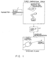
- FIG. 1 shows the interface apparatus according to the present invention.
- the interface apparatus shown in FIG. 1 comprises a plane designation unit 1 and a display unit 2.
- the plane designation unit 1 designates an arbitrary plane in a three-dimensional space.
- the display unit 2 displays the image of a robot on the designated plane in the graphics representation.
- the plane designation unit 1 designates the position and orientation of a plane in the three-dimensional space depending on the parameter value input by an operator.
- the position and orientation of a plane can be freely changed, and an arbitrary plane can be set.
- the display unit 2 displays in the three-dimensional CG the image of a robot viewed from the plane set in the three-dimensional space.
- the operator can freely select an arbitrary two-dimensional plane for display.
- the target position can be easily designated on the displayed screen only by displaying the plane containing the current position and the target position. At this time, since it is assumed that the end effector moves on the displayed plane from the current position to the target position, the operator can easily and visually predict the operation of the robot.
- the interface apparatus shown in FIG. 1 is used not only to position the end effector but also to operate other specific portions of the robot. In this case, the operations of the robot can be easily predicted by displaying the plane containing the current position and the target position of the specific portion of the robot.
- the plane designation unit 1 shown in FIG. 1 corresponds to a CPU (central processing unit) 21, memory 22, and an input device 23 described later and shown in FIG. 3.
- the display unit 2 shown in FIG. 1 corresponds to the CPU 21, the memory 22, and an output device 24 shown in FIG. 3.
- the following conditions are set to easily position a robot in a robot simulation.
- a display window of three-dimensional CG displaying an arbitrary plane in a three-dimensional space in which the robot exists is used.
- the movable range of the end effector is limited to a two-dimensional plane.
- a sphere is assumed with a central point of the movable range of the end effector set as the center of the sphere.
- An arbitrary plane tangent to the sphere is defined as a display plane of the display window. The operator can dynamically changes the display plane only by changing the position of the contact point on the sphere, and the radius of the sphere.
- the display plane can be set in a plane containing the current position of the end effector.
- the display plane on the screen and the two-dimensional plane which is a movable range of the end effector are mapped.
- the operator designates a point on the plane displayed in the display window to determine the position and orientation of the end effector to be positioned.
- the designated point refers to the target position of the end effector, and the orientation of the end effector is determined based on the position of the contact point on the sphere, and the direction of the normal vector of the tangent plane at the contact point.
- an arbitrary two-dimensional plane can be set as necessary without preliminarily setting a number of coordinate systems of an end effector.
- the end effector can be easily positioned by predicting the operations of the end effector by mapping the tangent plane of the sphere on the display plane of the screen, and by limiting the movable range of the end effector to the display plane.
- FIG. 2 shows an example of the robot system to be processed in the simulation.
- the system shown in FIG. 2 contains a robot 11, an actuator 12, a sensor 13, a control device 14, and an interface 15. It is operated according to the operational input from the operator.
- the robot 11 is provided with a manipulator 17 mounted onto a base plate 16.
- the actuator 12 drives the robot 11 according to the control signal from the control device 14.
- the sensor 13 detects the position, speed, torque, etc. of each joint of the manipulator 17, and outputs signals corresponding to the values to the control device 14.
- the control device 14 contains a processing device for executing a program, and generates a control signal to be issued to the actuator 12 according to the information from the sensor 13.
- the interface 15 is an input/output device for functioning as an interface for exchanging information between the operator and the control device 14.
- the control device 14 and the interface 15 shown in FIG. 2 can be designed using an information processing device (computer) as shown in FIG. 3.
- the information processing device shown in FIG. 3 comprises the CPU 21, the memory 22, the input device 23, the output device 24, an external storage device 25, a medium drive device 26, and a network connection device 27. These units are interconnected through a bus 28.
- the memory 22 includes, for example, ROM (read only memory), RAM (random access memory), etc. and stores a program and data to be used in a robot system control process.
- the input device 23 is, for example, a keyboard, a pointing device, a touch panel, a joy stick, etc. to be used in inputting an instruction and information from an operator.
- the output device 24 is, for example, a display, a printer, etc., to be used in outputting an inquiry, a process result, etc. to the operator.
- the external storage device 25 is, for example, a magnetic disk device, an optical disk device, a magneto-optical disk device, etc.
- the external storage device 25 can store the above described program and data, which are used as necessary after being loaded onto the memory 22.
- the external storage device 25 can be used as a database.
- the medium drive device 26 drives a portable storage medium 29, and accesses the contents stored on the portable storage medium 29.
- the portable storage medium 29 can be an arbitrary computer-readable storage medium such as a memory card, a floppy disk, CD-ROM (compact disk read only memory), an optical disk, a magneto-optical disk, etc.
- the portable storage medium 29 can store the above described program and data, which are used as necessary after being loaded onto the memory 22.
- the network connection device 27 can communicate with an external device through a network (line) such as a LAN (local area network), etc. to convert data for communications. Furthermore, the network connection device 27 can receive as necessary the above described program and data from an external unit, and the information processing device uses them after loading them to the memory 22.
- a network such as a LAN (local area network), etc.
- FIG. 4 shows computer-readable storage media for providing a program and data for the information processing device shown in FIG. 3.
- the program and data stored on the portable storage medium 29 and in an external database 30 are loaded onto the memory 22.
- the CPU 21 executes the program using the data, and performs a necessary process.
- the information processing device shown in FIG. 3 is used not only for operational input to and the control of the robot system shown in FIG. 2, but also for the above described robot simulation.
- the CPU 21 executes a program for a kinetics simulation, etc. according to an operational input from the input device 23, and displays the result on the screen of the output device 24.
- the robot 11 has five rotatable joints having respective rotation angles (joint angles) of a variable ⁇ 1, ⁇ 2, ⁇ 3, ⁇ 4, and ⁇ 5.
- the coordinate system represented by these variables is hereinafter referred to as a joint angle coordinate system.
- the manipulator 17 takes a full-straight orientation, the relationship among the joints can be shown in FIG. 5.
- the rotation axes of ⁇ 1 and ⁇ 5 are in a straight line.
- the base coordinate system representing the position and orientation of the hand 18 includes, as shown in FIG. 6, five variables ⁇ b, Xb, Zb, ⁇ b, and ⁇ b. Among them, the rotation angles ⁇ b and ⁇ b respectively match ⁇ 1 and ⁇ 5 of the joint angle coordinate system.
- the plane Xb-Zb is vertical to the surface of the base plate 16. The origin matches the intersection between the surface of the base plate 16 and the rotation axis of ⁇ 1.
- the plane Xb-Zb rotates with the rotation angle ⁇ b.
- the rotation angle ⁇ b is defined in the plane Xb-Zb, and indicates the direction of the rotation axis of ⁇ b relative to the positive direction of the Zb axis.
- the position of the hand 18 is represented by the variables ⁇ b, Xb, and Zb
- the orientation is represented by the variables ⁇ b and ⁇ b.
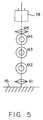
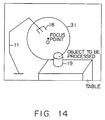
- a sphere 31 can be defined by designating the position of the center O in the three-dimensional space and the radius.
- a virtual camera 32 having the center as a focus point is provided on the surface of the sphere 31. It is assumed that the camera 32 can be freely moved on the sphere.
- the tangent plane which has the intersection between the axis of the lens of the camera 32 and the surface of the sphere as a contact point, is defined as the display plane of the image captured by the camera 32, and is associated with the display plane of the three-dimensional CG.
- the camera 32 can be rotated on the surface of the sphere by 360° in the direction of the equator, and 360° in the direction of the polar orbit.
- the camera 32 can capture the image in an arbitrary two-dimensional plane in the three-dimensional space.
- a Denavit-Hartenberg model which is often used to represent the movement of a robot can be utilized.
- a robot is assumed to be a linked mechanism formed by a plurality of links coupled by joints.
- a three-dimensional coordinate system is defined for each joint, and the relative relationship among the coordinate systems is represented by four parameters (Basic Robot Engineering Control, P52 - 56, by Kensuke Hasegawa and Ryosuke Masuda, published by Shokodo).
- the parameters are called DH parameters.
- the DH model of the virtual robot (arbitrary view point robot) for representing an arbitrary position and orientation using the camera 32 has the first, second, third, fourth, and fifth joints sequentially coupled using links having the length of 0.
- the first, second, third, fourth, and fifth camera coordinate systems are respectively set to the joints.
- the origin of the first camera coordinate system is, for example, connected to the origin of the absolute coordinate system with a finite-length link, and is fixed to the center O of the sphere 31.
- the length of the link depends on the position of the center O.
- the origins of the other camera coordinate systems are all degenerated to the center O.
- the first joint is a fixed type.
- the second, third, and fourth joints are a rotational type.
- the fifth joint is a translational type.
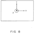
- FIG. 8 shows the state of the first camera coordinate system viewed from the positive direction of the Z axis toward the origin.
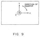
- the second joint rotates in the direction of the equator, and the corresponding second camera coordinate system matches the first camera coordinate system as shown in FIG. 9. Therefore, the DH parameters of the second camera coordinate system are (0, 0, 0, 0).
- the third joint rotates in the direction of the polar orbit, and the corresponding third camera coordinate system is represented as shown in FIG. 10.
- the DH parameters of the third camera coordinate system are (0, 0, - ⁇ /2, 0).
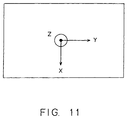
- the fourth joint is provided as a dummy for changing the direction of the camera 32.
- the corresponding fourth camera coordinate system is represented as shown in FIG. 11.
- the DH parameters of the fourth camera coordinate system are (0, 0, ⁇ /2, - ⁇ /2).
- the fifth joint slides in the radius direction, and the corresponding fifth camera coordinate system matches the fourth camera coordinate system as shown in FIG. 12. Therefore, the DH parameters of the fifth camera coordinate system are (0, 0, 0, 0).
- the position of the camera 32 can be determined by designating the rotation angles in the directions of the equator and the polar orbit, and the translational distance in the radius direction. Based on the determined position, the movable plane of the hand 18 can be set.
- FIG. 13 is a flowchart of the positioning process. The process is used in a simulation of a robot system or an actual operation.
- the operator designates as the position of the center O (focus point) of the sphere 31 an arbitrary point in the three-dimensional space containing the robot 11 and the object 19 (cylinder) to be processed (step S1).
- the object 19 is placed on a table, and the position of the center O is designated in the absolute coordinate system.
- the position of the center O is set in the vicinity of the center of the space in which the object 19 can move around, the following operations can be easily performed.
- the robot 11, the object 19, etc. in the vicinity are displayed on the tangent plane (initial plane) on the sphere 31 as shown in FIG. 15.
- the parameters (the amount of rotation in the direction of the equator, the amount of rotation in the direction of the polar orbit, and the length in the radius direction) which determine the initial plane are preliminarily assigned as initial values.
- the operator designates an arbitrary tangent plane of the sphere 31 through the graphical user interface (GUI)(step S2).
- GUI graphical user interface
- the setting screen as shown in FIG. 16 is displayed on the display device.
- the amount of rotation in the direction of the equator, the amount of rotation in the direction of the polar orbit, and the length in the radius direction can be designated by sliding volumes 41, 42, and 43. If defaults 44, 45, and 46 are designated, the defaults of the amount of rotation in the direction of the equator, the amount of rotation in the direction of the polar orbit, and the length in the radius direction can be automatically set.
- the order of setting the parameters can be arbitrarily determined.
- the information processing device converts the input value of each parameter into the rotation angle or the translational distance of each joint of the DH model of the above described camera 32, performs a kinematics operation based on the conversion result, and determines the position of the camera 32. Then, the three-dimensional CG is generated on the tangent plane having the determined position as a contact point, and is then displayed in the display window (step S3).
- the operator checks whether or not the displayed screen contains the current position and the target position of the hand 18, and inputs an instruction to or not to determine the display screen (step S4). If the screen is not to be determined, the processes in and after step S2 are repeated.
- FIG. 17 shows the screen on which an amendment is made to the length in the radius direction shown in FIG. 15, and the vicinity of the hand 18 and the object 19 is enlarged.
- the operator rotates the camera 32 in the direction of the polar orbit to hold the object 19 on the table with the hand 18.
- the operator amends the display screen such that the current position P1 of the hand 18 and the target position P2 right above the object 19 can be on the same plane.
- the operator determines the screen.
- the movable area of the hand 18 is limited to the display plane.
- the information processing device When the screen is determined, the information processing device performs a mapping process in the three-dimensional space on the determined screen and the absolute coordinate system space (step S5).
- the operator designates the target position and the target orientation of the hand 18 in the display window using a pointing device such as a mouse, etc. (steps S6 and S7).
- the two-dimensional coordinates on the display screen are designated as a target position using the left button of the mouse, and the target orientation is designated using the right button of the mouse.
- the information processing device can automatically determine the target orientation without the operator designating it.
- the orientation of the hand 18 is determined such that the hand 18 faces the direction (vertical to the screen) of the normal vector on the displayed two-dimensional plane.
- the information processing device transforms the coordinates from the absolute coordinate system to the base coordinate system (step S8) for the designated target position and orientation, and then performs an inverse kinematics operation to transform the target position and orientation from the base coordinate system to the joint angle coordinate system (step S9).
- a kinematics operation is performed based on the obtained rotation angle of each joint angle, and the image of the hand 18 at the target position is displayed in the three-dimensional manner (step S10).
- the target position P2 shown in FIG. 18 is designated, for example, an image as shown in FIG. 19 is displayed.
- the operator determines whether or not the displayed target position and orientation can be accepted, and inputs an instruction to or not to determine the position and orientation (step S11).
- the target position and orientation are not determined, the processes in and after step S6 are repeated.
- the information processing device When the target position and orientation are determined, the information processing device generates a path from the current position and orientation of the robot 11 to its target position and orientation (step S12), thereby terminating the process.
- a path In a robot simulation, images of the moving hand 18 are displayed based on the generated path.
- the control signal corresponding to the generated path is output to the actuator 12. In the case shown in FIG. 19, it is assumed that the hand 18 has held the object 19 at the target position P2.
- the operator can obtain an image on an arbitrary plane in the three-dimensional space with a simple operation, thereby visually recognizing the robot 11, object 19, etc. from various view points. Furthermore, a plane containing a specific portion of the robot 11 and the object 19 can be easily displayed by moving the display plane in a three-dimensional manner. It is easy to designate the position of the object 19 as a target position of the robot 11 on the above described plane, thereby easily predicting the movement of the robot 11 in its way from the current position to the target position.
- the operator rotates the tangent plane in the direction of the polar orbit by 90° in step S2 to confirm the plane (on the table) along the depth of the screen.
- the screen is amended such that the current position P2 and the target position P3 of the hand 18 can be on the same plane.
- an image of the plane containing the current position P2 and the target position P3 is displayed.
- a new path can be generated by designating the target position P3 and the orientation of the hand 18 at the position.
- the absolute coordinate system (Xa, Ya, Za, ⁇ a, ⁇ a) is defined, for example, as follows.
- Equation (1) is used when a tangent plane designated in step S2 is transformed into the base coordinate system. It is also used when the target position and orientation of the hand 18 designated in steps S6 and S7 are transformed into the base coordinate system in step S8.
- the length of each link is represented as L1, L2, L3, L4, and L5.
- the variables ( ⁇ 1, ⁇ 2, ⁇ 3, ⁇ 4, 5 ⁇ ) of the joint angle coordinate system are transformed into the variables ( ⁇ b, Xb, Zb, ⁇ b, ⁇ b) of the base coordinate system according to the following equations.
- Xb L2sin ( ⁇ 2)+ L3sin ( ⁇ 2+ ⁇ 3) +( L4 + L5 )sin( ⁇ 2+ ⁇ 3+ ⁇ 4)
- Zb L1 + L2cos ( ⁇ 2)+ L3cos ( ⁇ 2+ ⁇ 3) +( L4 + L5 )cos( ⁇ 2+ ⁇ 3+ ⁇ 4)
- ⁇ b ⁇ 2+ ⁇ 3+ ⁇ 4
- Equation (3) is used when, for example, a three-dimensional CG image is generated in steps S3 and S10.
- R 2 Px 2 + Pz 2
- Equation (4) is used when, for example, the target position and orientation of the hand 18 represented in the base coordinate system are transformed into the joint angle coordinate system in step S9.
- FIG. 22 is a flowchart of the path generating process performed in step S12 shown in FIG. 13.
- a command string input data of a control signal of the control device 14 for instructing the robot 11 to perform the operations for reaching the target position and orientation from the current position and orientation of the hand 18 is generated, and is then stored in the command accumulation file provided in the memory 22 shown in FIG. 3.
- a command string is generated with the path from the current position and orientation to the target position and orientation processed as a single path.
- the process from the current position and orientation to the target position and orientation is divided into a number of paths to generate a command string.
- the information processing device first computes the amount of movement in an assigned path from the start to the end (step S21), and obtains the number (integer) of divisions of the path based on the predetermined amount of movement per command (step S22). Then, each division point is computed based on the number of divisions (step S23), and is written to the command accumulation file (step S24), thereby terminating the process.
- the information processing device computes the rotation angle in the joint angle coordinate system in step S21, and computes the division points in the joint angle coordinate system in step S23. Then, in step S24, each division point is converted into a command, and is written to the command accumulation file.
- the information processing device computes the moving distance in the absolute coordinate system in step S21, and computes the division points in the absolute coordinate system in step S23. Then, in step S24, each division point is transformed into the base coordinate system by equations (1), and into the joint angle coordinate system by equations (4). Then, each division point in the joint angle coordinate system is converted into a command, and is written to the command accumulation file.
- images of the movements of the hand 18 are displayed by performing kinematics operations according to the command string stored in the command accumulation file.
- the hand 18 is actually moved by outputting a control signal corresponding to the command string to the actuator 12.
- a virtual sphere is used in designating an arbitrary two-divisional plane in a three-dimensional space.
- the method of setting a two-dimensional plane is not limited to this example.
- a two-dimensional plane 51 is defined in a three-dimensional space. Then, using the two-dimensional plane 51 as a substitute for the end effector of a virtual robot formed by links 52 of a finite length, the two-dimensional plane 51 can be set to an arbitrary position and orientation.
- an end effector is an object to be positioned.
- a specific joint and link can be set at a target position and orientation.
- the body of the robot can be moved to a target position.
- the interface according to the present invention can be applied not only to a robot working on the ground, but also to a robot working anywhere, such as, underground, underwater, in the air, in space, etc.
- the robot hand when it is used for remote control of the robot hand system provided in a satellite, the robot hand can be more freely positioned, and an arbitrary position can be easily set in addition to the setting in a predetermined coordinate system.
- the operator can predict the operation of the robot from the current position to the target position when the robot is positioned in a three-dimensional space, thereby improving the operation efficiency.
- the robot can be easily positioned anywhere in the three-dimensional space.
Landscapes
- Engineering & Computer Science (AREA)
- Robotics (AREA)
- Mechanical Engineering (AREA)
- Numerical Control (AREA)
- Manipulator (AREA)
Applications Claiming Priority (2)
| Application Number | Priority Date | Filing Date | Title |
|---|---|---|---|
| JP04383798A JP3655083B2 (ja) | 1998-02-25 | 1998-02-25 | ロボットの位置決めを行うインタフェース装置 |
| JP4383798 | 1998-02-25 |
Publications (2)
| Publication Number | Publication Date |
|---|---|
| EP0938954A2 true EP0938954A2 (de) | 1999-09-01 |
| EP0938954A3 EP0938954A3 (de) | 2004-04-21 |
Family
ID=12674869
Family Applications (1)
| Application Number | Title | Priority Date | Filing Date |
|---|---|---|---|
| EP99102799A Withdrawn EP0938954A3 (de) | 1998-02-25 | 1999-02-25 | Schnittellengerät zur Positionierung eines Roboters |
Country Status (3)
| Country | Link |
|---|---|
| US (1) | US6642922B1 (de) |
| EP (1) | EP0938954A3 (de) |
| JP (1) | JP3655083B2 (de) |
Cited By (5)
| Publication number | Priority date | Publication date | Assignee | Title |
|---|---|---|---|---|
| WO2002062535A3 (en) * | 2001-02-07 | 2004-03-04 | Giovanni Pioggia | Method for controlling an articulated and/or deformable mechanical system and its applications |
| EP1247623A3 (de) * | 2001-04-05 | 2005-05-11 | Fanuc Ltd | System zur Informationsverarbeitung für Roboter |
| CN103085071A (zh) * | 2013-02-04 | 2013-05-08 | 惠州市东扬科技有限公司 | 一种可视化机器人程序编译方法 |
| CN105486465A (zh) * | 2015-11-19 | 2016-04-13 | 中国商用飞机有限责任公司 | 自动检测工装及其检测方法 |
| US10759050B2 (en) | 2015-12-11 | 2020-09-01 | Abb Schweiz Ag | Robot off-line programming method and apparatus using the same |
Families Citing this family (28)
| Publication number | Priority date | Publication date | Assignee | Title |
|---|---|---|---|---|
| JP3537362B2 (ja) * | 1999-10-12 | 2004-06-14 | ファナック株式会社 | ロボットシステム用グラフィック表示装置 |
| US7802193B1 (en) | 2001-12-19 | 2010-09-21 | Sandia Corporation | Controlling motion using a human machine interface |
| JP3797986B2 (ja) * | 2003-07-03 | 2006-07-19 | ファナック株式会社 | ロボットオフラインシミュレーション装置 |
| FR2872728B1 (fr) * | 2004-07-06 | 2006-09-15 | Commissariat Energie Atomique | Procede de saisie d'un objet par un bras de robot muni d'une camera |
| JP2007244569A (ja) * | 2006-03-15 | 2007-09-27 | Shimadzu Corp | 天井走行懸垂型のx線撮影装置 |
| JP2007286976A (ja) * | 2006-04-18 | 2007-11-01 | Fanuc Ltd | ロボットシミュレーション装置 |
| JP2008021092A (ja) * | 2006-07-12 | 2008-01-31 | Fanuc Ltd | ロボットシステムのシミュレーション装置 |
| EP2206093B1 (de) * | 2007-11-02 | 2013-06-26 | Koninklijke Philips Electronics N.V. | Automatische fly-path-berechnung für filme |
| JP4347386B2 (ja) * | 2008-01-23 | 2009-10-21 | ファナック株式会社 | 加工用ロボットプラグラムの作成装置 |
| JP4508252B2 (ja) | 2008-03-12 | 2010-07-21 | 株式会社デンソーウェーブ | ロボット教示装置 |
| JP5201341B2 (ja) * | 2008-09-09 | 2013-06-05 | 富士電機株式会社 | 遠隔操作支援装置 |
| JP5338408B2 (ja) * | 2009-03-19 | 2013-11-13 | 株式会社デンソーウェーブ | ロボットシミュレータ |
| GB2477347A (en) * | 2010-02-01 | 2011-08-03 | Cambridge Entpr Ltd | A Hand Operated Controller |
| FI20105732A0 (fi) * | 2010-06-24 | 2010-06-24 | Zenrobotics Oy | Menetelmä fyysisten kappaleiden valitsemiseksi robottijärjestelmässä |
| JP5547626B2 (ja) * | 2010-12-28 | 2014-07-16 | 川崎重工業株式会社 | 7軸多関節ロボットの制御装置および教示方法 |
| EP2864082B1 (de) | 2012-06-26 | 2018-11-07 | ABB Schweiz AG | Einstellung von parametern eines dynamischen robotermodells |
| WO2015079740A1 (ja) * | 2013-11-28 | 2015-06-04 | 三菱電機株式会社 | ロボットシステムおよびロボットシステムの制御方法 |
| JP5850958B2 (ja) * | 2014-01-24 | 2016-02-03 | ファナック株式会社 | ワークを撮像するためのロボットプログラムを作成するロボットプログラミング装置 |
| JP6529758B2 (ja) * | 2014-12-25 | 2019-06-12 | 株式会社キーエンス | 画像処理装置、画像処理システム、画像処理方法及びコンピュータプログラム |
| JP6486679B2 (ja) * | 2014-12-25 | 2019-03-20 | 株式会社キーエンス | 画像処理装置、画像処理システム、画像処理方法及びコンピュータプログラム |
| US9478064B2 (en) * | 2015-01-29 | 2016-10-25 | Harris Corporation | Automatic control of avatar perspective view in a graphical user interface |
| JP6392817B2 (ja) * | 2016-08-04 | 2018-09-19 | ファナック株式会社 | シミュレーション装置 |
| JP6889574B2 (ja) * | 2017-03-03 | 2021-06-18 | 株式会社キーエンス | ロボット設定装置、ロボット設定方法、ロボット設定プログラム及びコンピュータで読み取り可能な記録媒体並びに記録した機器 |
| CN109048916A (zh) * | 2018-09-12 | 2018-12-21 | 遂昌睿丰科技有限公司 | 基于多维传感器实时数据反馈融合的便捷式工业机器人 |
| JP7272825B2 (ja) * | 2019-03-06 | 2023-05-12 | ファナック株式会社 | ロボットシステム |
| JP7543006B2 (ja) * | 2020-06-24 | 2024-09-02 | 株式会社クボタ | 農業用ロボット |
| JP7599366B2 (ja) * | 2021-03-31 | 2024-12-13 | 本田技研工業株式会社 | ロボット遠隔操作制御装置、ロボット遠隔操作制御システム、ロボット遠隔操作制御方法、およびプログラム |
| CN113386112A (zh) * | 2021-07-29 | 2021-09-14 | 厦门凤凰创壹软件有限公司 | 一种可控制多种品牌三维虚拟工业机器人的示教器 |
Family Cites Families (14)
| Publication number | Priority date | Publication date | Assignee | Title |
|---|---|---|---|---|
| US3892051A (en) * | 1973-10-31 | 1975-07-01 | Gen Electric | Simulated collimation of computer generated images |
| US4734690A (en) * | 1984-07-20 | 1988-03-29 | Tektronix, Inc. | Method and apparatus for spherical panning |
| JPH0772844B2 (ja) * | 1985-10-23 | 1995-08-02 | 株式会社日立製作所 | ロボット教示装置 |
| US4987527A (en) * | 1987-10-26 | 1991-01-22 | Hitachi, Ltd. | Perspective display device for displaying and manipulating 2-D or 3-D cursor, 3-D object and associated mark position |
| US5046022A (en) * | 1988-03-10 | 1991-09-03 | The Regents Of The University Of Michigan | Tele-autonomous system and method employing time/position synchrony/desynchrony |
| US5253189A (en) * | 1989-06-13 | 1993-10-12 | Schlumberger Technologies, Inc. | Qualitative kinematics |
| JPH0699375A (ja) * | 1992-09-18 | 1994-04-12 | Kawasaki Heavy Ind Ltd | ロボット操作訓練装置 |
| US5581666A (en) * | 1993-08-04 | 1996-12-03 | Anderson; Robert J. | Modular architecture for robotics and teleoperation |
| JP3486461B2 (ja) * | 1994-06-24 | 2004-01-13 | キヤノン株式会社 | 画像処理装置及び方法 |
| US5495410A (en) * | 1994-08-12 | 1996-02-27 | Minnesota Mining And Manufacturing Company | Lead-through robot programming system |
| US5771310A (en) * | 1996-12-30 | 1998-06-23 | Shriners Hospitals For Children | Method and apparatus for recording three-dimensional topographies |
| CA2213884C (en) * | 1996-08-21 | 2001-05-22 | Nippon Telegraph And Telephone Corporation | Method for generating animations of a multi-articulated structure, recording medium having recorded thereon the same and animation generating apparatus using the same |
| JPH1177569A (ja) * | 1997-09-10 | 1999-03-23 | Honda Motor Co Ltd | オフラインティーチング装置 |
| US6556206B1 (en) * | 1999-12-09 | 2003-04-29 | Siemens Corporate Research, Inc. | Automated viewpoint selection for 3D scenes |
-
1998
- 1998-02-25 JP JP04383798A patent/JP3655083B2/ja not_active Expired - Fee Related
-
1999
- 1999-02-19 US US09/252,830 patent/US6642922B1/en not_active Expired - Fee Related
- 1999-02-25 EP EP99102799A patent/EP0938954A3/de not_active Withdrawn
Cited By (5)
| Publication number | Priority date | Publication date | Assignee | Title |
|---|---|---|---|---|
| WO2002062535A3 (en) * | 2001-02-07 | 2004-03-04 | Giovanni Pioggia | Method for controlling an articulated and/or deformable mechanical system and its applications |
| EP1247623A3 (de) * | 2001-04-05 | 2005-05-11 | Fanuc Ltd | System zur Informationsverarbeitung für Roboter |
| CN103085071A (zh) * | 2013-02-04 | 2013-05-08 | 惠州市东扬科技有限公司 | 一种可视化机器人程序编译方法 |
| CN105486465A (zh) * | 2015-11-19 | 2016-04-13 | 中国商用飞机有限责任公司 | 自动检测工装及其检测方法 |
| US10759050B2 (en) | 2015-12-11 | 2020-09-01 | Abb Schweiz Ag | Robot off-line programming method and apparatus using the same |
Also Published As
| Publication number | Publication date |
|---|---|
| JPH11242513A (ja) | 1999-09-07 |
| JP3655083B2 (ja) | 2005-06-02 |
| US6642922B1 (en) | 2003-11-04 |
| EP0938954A3 (de) | 2004-04-21 |
Similar Documents
| Publication | Publication Date | Title |
|---|---|---|
| EP0938954A2 (de) | Schnittellengerät zur Positionierung eines Roboters | |
| EP2355956B1 (de) | Verfahren und vorrichtung zur optimierung eines programmierten bewegungswegs für einen industrieroboter | |
| Newman et al. | Real-time configuration space transforms for obstacle avoidance | |
| JP3415427B2 (ja) | ロボットシミュレーションにおけるキャリブレーション装置 | |
| JPH08108383A (ja) | マニピュレータ制御装置 | |
| Murray et al. | A planar quaternionapproach to the kinematic synthesis of a parallel manipulator | |
| Lambert et al. | A novel 5 DOF fully parallel robot combining 3T1R motion and grasping | |
| Jazar | Forward kinematics | |
| JP4230196B2 (ja) | 位置決め演算方法および位置決め演算装置 | |
| Khalil | Modeling and Control of Manipulators-Part I: Geometric and Kinematic Models | |
| Bejczy | Virtual reality in manufacturing | |
| Parkin | An interactive robotic simulation package | |
| Sabater et al. | Magister-P; a 6-URS parallel haptic device with open control architecture | |
| Wagner et al. | Computer aided design of robot trajectories using rational motions | |
| Cote et al. | Telemanipulator design and optimization software | |
| Yang | A numerical formulation for kinematic working capability analysis of mechanisms | |
| Chen et al. | Fundamentals of Robotic Kinematics | |
| Seth et al. | A virtual reality interface for the design of compliant mechanisms | |
| Vitalli | Virtual Commissioning, Digital Twin and Control Strategies Applied in the Industrial Robot PUMA 560 | |
| Fomin et al. | Inverse and Forward Kinematic Analysis of a 6-DOF Parallel Manipulator Utilizing a Circular Guide. Robotics 2021, 10, 31 | |
| Tabani et al. | Robot motion and task planning: simulation and programming of a robot arm | |
| Namgung | Planning collision-free paths with applications to robot manipulators | |
| Pająk et al. | The robot toolbox for Matlab | |
| Harris-Coppola | Analytical and visual tools for robot kinematics | |
| Troy | An interactive graphical approach to off-line programming |
Legal Events
| Date | Code | Title | Description |
|---|---|---|---|
| PUAI | Public reference made under article 153(3) epc to a published international application that has entered the european phase |
Free format text: ORIGINAL CODE: 0009012 |
|
| AK | Designated contracting states |
Kind code of ref document: A2 Designated state(s): AT BE CH CY DE DK ES FI FR GB GR IE IT LI LU MC NL PT SE |
|
| AX | Request for extension of the european patent |
Free format text: AL;LT;LV;MK;RO;SI |
|
| PUAL | Search report despatched |
Free format text: ORIGINAL CODE: 0009013 |
|
| AK | Designated contracting states |
Kind code of ref document: A3 Designated state(s): AT BE CH CY DE DK ES FI FR GB GR IE IT LI LU MC NL PT SE |
|
| AX | Request for extension of the european patent |
Extension state: AL LT LV MK RO SI |
|
| 17P | Request for examination filed |
Effective date: 20041018 |
|
| AKX | Designation fees paid |
Designated state(s): DE FR GB |
|
| 17Q | First examination report despatched |
Effective date: 20071217 |
|
| GRAP | Despatch of communication of intention to grant a patent |
Free format text: ORIGINAL CODE: EPIDOSNIGR1 |
|
| STAA | Information on the status of an ep patent application or granted ep patent |
Free format text: STATUS: THE APPLICATION IS DEEMED TO BE WITHDRAWN |
|
| 18D | Application deemed to be withdrawn |
Effective date: 20090827 |