EP0939207A1 - Neue katalytische Einheit zur Behandlung von Abgasen einer Brennkraftmaschine - Google Patents
Neue katalytische Einheit zur Behandlung von Abgasen einer Brennkraftmaschine Download PDFInfo
- Publication number
- EP0939207A1 EP0939207A1 EP99400418A EP99400418A EP0939207A1 EP 0939207 A1 EP0939207 A1 EP 0939207A1 EP 99400418 A EP99400418 A EP 99400418A EP 99400418 A EP99400418 A EP 99400418A EP 0939207 A1 EP0939207 A1 EP 0939207A1
- Authority
- EP
- European Patent Office
- Prior art keywords
- volume
- catalytic element
- catalytic
- monolith
- elements
- Prior art date
- Legal status (The legal status is an assumption and is not a legal conclusion. Google has not performed a legal analysis and makes no representation as to the accuracy of the status listed.)
- Granted
Links
Images

Classifications
-
- F—MECHANICAL ENGINEERING; LIGHTING; HEATING; WEAPONS; BLASTING
- F01—MACHINES OR ENGINES IN GENERAL; ENGINE PLANTS IN GENERAL; STEAM ENGINES
- F01N—GAS-FLOW SILENCERS OR EXHAUST APPARATUS FOR MACHINES OR ENGINES IN GENERAL; GAS-FLOW SILENCERS OR EXHAUST APPARATUS FOR INTERNAL-COMBUSTION ENGINES
- F01N3/00—Exhaust or silencing apparatus having means for purifying, rendering innocuous, or otherwise treating exhaust
- F01N3/08—Exhaust or silencing apparatus having means for purifying, rendering innocuous, or otherwise treating exhaust for rendering innocuous
- F01N3/10—Exhaust or silencing apparatus having means for purifying, rendering innocuous, or otherwise treating exhaust for rendering innocuous by thermal or catalytic conversion of noxious components of exhaust
- F01N3/24—Exhaust or silencing apparatus having means for purifying, rendering innocuous, or otherwise treating exhaust for rendering innocuous by thermal or catalytic conversion of noxious components of exhaust characterised by constructional aspects of converting apparatus
- F01N3/28—Construction of catalytic reactors
- F01N3/2839—Arrangements for mounting catalyst support in housing, e.g. with means for compensating thermal expansion or vibration
- F01N3/2842—Arrangements for mounting catalyst support in housing, e.g. with means for compensating thermal expansion or vibration specially adapted for monolithic supports, e.g. of honeycomb type
-
- F—MECHANICAL ENGINEERING; LIGHTING; HEATING; WEAPONS; BLASTING
- F01—MACHINES OR ENGINES IN GENERAL; ENGINE PLANTS IN GENERAL; STEAM ENGINES
- F01N—GAS-FLOW SILENCERS OR EXHAUST APPARATUS FOR MACHINES OR ENGINES IN GENERAL; GAS-FLOW SILENCERS OR EXHAUST APPARATUS FOR INTERNAL-COMBUSTION ENGINES
- F01N13/00—Exhaust or silencing apparatus characterised by constructional features
- F01N13/009—Exhaust or silencing apparatus characterised by constructional features having two or more separate purifying devices arranged in series
- F01N13/0097—Exhaust or silencing apparatus characterised by constructional features having two or more separate purifying devices arranged in series the purifying devices are arranged in a single housing
-
- F—MECHANICAL ENGINEERING; LIGHTING; HEATING; WEAPONS; BLASTING
- F01—MACHINES OR ENGINES IN GENERAL; ENGINE PLANTS IN GENERAL; STEAM ENGINES
- F01N—GAS-FLOW SILENCERS OR EXHAUST APPARATUS FOR MACHINES OR ENGINES IN GENERAL; GAS-FLOW SILENCERS OR EXHAUST APPARATUS FOR INTERNAL-COMBUSTION ENGINES
- F01N3/00—Exhaust or silencing apparatus having means for purifying, rendering innocuous, or otherwise treating exhaust
- F01N3/08—Exhaust or silencing apparatus having means for purifying, rendering innocuous, or otherwise treating exhaust for rendering innocuous
- F01N3/10—Exhaust or silencing apparatus having means for purifying, rendering innocuous, or otherwise treating exhaust for rendering innocuous by thermal or catalytic conversion of noxious components of exhaust
- F01N3/18—Exhaust or silencing apparatus having means for purifying, rendering innocuous, or otherwise treating exhaust for rendering innocuous by thermal or catalytic conversion of noxious components of exhaust characterised by methods of operation; Control
- F01N3/20—Exhaust or silencing apparatus having means for purifying, rendering innocuous, or otherwise treating exhaust for rendering innocuous by thermal or catalytic conversion of noxious components of exhaust characterised by methods of operation; Control specially adapted for catalytic conversion
- F01N3/2053—By-passing catalytic reactors, e.g. to prevent overheating
-
- F—MECHANICAL ENGINEERING; LIGHTING; HEATING; WEAPONS; BLASTING
- F01—MACHINES OR ENGINES IN GENERAL; ENGINE PLANTS IN GENERAL; STEAM ENGINES
- F01N—GAS-FLOW SILENCERS OR EXHAUST APPARATUS FOR MACHINES OR ENGINES IN GENERAL; GAS-FLOW SILENCERS OR EXHAUST APPARATUS FOR INTERNAL-COMBUSTION ENGINES
- F01N3/00—Exhaust or silencing apparatus having means for purifying, rendering innocuous, or otherwise treating exhaust
- F01N3/08—Exhaust or silencing apparatus having means for purifying, rendering innocuous, or otherwise treating exhaust for rendering innocuous
- F01N3/10—Exhaust or silencing apparatus having means for purifying, rendering innocuous, or otherwise treating exhaust for rendering innocuous by thermal or catalytic conversion of noxious components of exhaust
- F01N3/24—Exhaust or silencing apparatus having means for purifying, rendering innocuous, or otherwise treating exhaust for rendering innocuous by thermal or catalytic conversion of noxious components of exhaust characterised by constructional aspects of converting apparatus
- F01N3/28—Construction of catalytic reactors
- F01N3/2882—Catalytic reactors combined or associated with other devices, e.g. exhaust silencers or other exhaust purification devices
- F01N3/2885—Catalytic reactors combined or associated with other devices, e.g. exhaust silencers or other exhaust purification devices with exhaust silencers in a single housing
-
- F—MECHANICAL ENGINEERING; LIGHTING; HEATING; WEAPONS; BLASTING
- F01—MACHINES OR ENGINES IN GENERAL; ENGINE PLANTS IN GENERAL; STEAM ENGINES
- F01N—GAS-FLOW SILENCERS OR EXHAUST APPARATUS FOR MACHINES OR ENGINES IN GENERAL; GAS-FLOW SILENCERS OR EXHAUST APPARATUS FOR INTERNAL-COMBUSTION ENGINES
- F01N3/00—Exhaust or silencing apparatus having means for purifying, rendering innocuous, or otherwise treating exhaust
- F01N3/08—Exhaust or silencing apparatus having means for purifying, rendering innocuous, or otherwise treating exhaust for rendering innocuous
- F01N3/10—Exhaust or silencing apparatus having means for purifying, rendering innocuous, or otherwise treating exhaust for rendering innocuous by thermal or catalytic conversion of noxious components of exhaust
- F01N3/24—Exhaust or silencing apparatus having means for purifying, rendering innocuous, or otherwise treating exhaust for rendering innocuous by thermal or catalytic conversion of noxious components of exhaust characterised by constructional aspects of converting apparatus
- F01N3/28—Construction of catalytic reactors
- F01N3/2892—Exhaust flow directors or the like, e.g. upstream of catalytic device
-
- F—MECHANICAL ENGINEERING; LIGHTING; HEATING; WEAPONS; BLASTING
- F01—MACHINES OR ENGINES IN GENERAL; ENGINE PLANTS IN GENERAL; STEAM ENGINES
- F01N—GAS-FLOW SILENCERS OR EXHAUST APPARATUS FOR MACHINES OR ENGINES IN GENERAL; GAS-FLOW SILENCERS OR EXHAUST APPARATUS FOR INTERNAL-COMBUSTION ENGINES
- F01N1/00—Silencing apparatus characterised by method of silencing
- F01N1/08—Silencing apparatus characterised by method of silencing by reducing exhaust energy by throttling or whirling
- F01N1/089—Silencing apparatus characterised by method of silencing by reducing exhaust energy by throttling or whirling using two or more expansion chambers in series
Definitions
- the present invention relates to the field of gas treatment exhaust from an internal combustion engine.
- the invention relates to the catalytic depollution of these exhaust gas.
- a first way consists in equipping the exhaust line with two catalysts.
- US Patent 5,377,486 is an example.
- a main monolith in which the gas will constantly pass exhaust is preceded by a monolith called "light-of" or “priming” in which the gases will pass when the engine starts, so when they do not are not yet very hot.
- the monolith “of light off” is however effective from the first moments of system operation.
- a winnowing pilot will allow to bypass this first catalyst to send gas directly in the main monolith.
- the gaseous mixture although containing a lot of oxygen, may however not contain enough of it to oxidize both carbon monoxide and hydrocarbons (to CO 2 and H 2 O). Part of the hydrocarbons is then only partially oxidized to form carbon monoxide in the catalyst. The catalytic efficiency with respect to CO will therefore be a compromise between the CO oxidized to CO 2 and the CO reformed by this partial oxidation of the hydrocarbons. This process is favored at high temperature.
- the present invention notably represents a solution to problem of monoliths placed at the exhaust of two-stroke engines; the temperature rise is favorably reduced according to the invention; of the more the space constraints are respected; moreover the present invention can be added to an existing exhaust, quick and easy.
- the present invention makes it possible to use certain characteristics of metal monoliths known to eliminate problems of excessive exothermicity. It also helps maintain sustainably catalytic performance.
- the subject of the invention is a catalytic element intended to eliminate pollutants from exhaust gases from internal combustion engines, comprising at least one monolith wrapped in a ferrule.
- said monolith comprises two separate elements by an empty volume delimited by said ferrule and a face of each of elements.
- said ferrule includes openings placed at the level of the empty volume.
- At least one of the elements protrudes over part of its length, outside the shell.
- none of the said elements does not protrude from the shell.
- the volumes of each of said elements may be different.
- the cell density of each of the monoliths can be different.
- each of the monoliths can be different. Without departing from the scope of the invention, it can also be the same.
- the openings may have inclined edges so as to guiding the gas flow inside said empty volume.
- the shell includes, at the empty volume and downstream of said openings, at least one circumferential groove hollowed out towards inside the shell.
- said empty volume is coated internally with a catalytic layer.
- the element catalytic is placed inside a silencer that is part of the line exhaust.
- the invention further relates to a silencer comprising an element catalytic and further comprising at least one inlet and at least an outlet for the exhaust gases, a double envelope delimiting a intermediate volume and the interior volume of the silencer, a wall intended to separate said interior volume into two parts, upstream and downstream and on which the catalytic element is mounted in such a way that the first monolith is located in the upstream part and that the second monolith is located in the downstream part, said openings of the catalytic element being located on the side downstream ; the internal envelope has openings located on the downstream side of so that a fluid flowing in the intermediate volume can penetrate in said downstream volume through said openings and then through the second monolith.
- the fluid in the intermediate volume can be air and / or gases exhaust to be treated.
- Figure 1 is a diagram of an exhaust line which includes a pipe 1 having a first end 2 connected to the engine outlet (not shown); at its second end 3 the pipe opens, according to what embodiment of the invention, in a casing 4 which is usually used silent. More precisely, the pipe 1 exceeds a certain length inside the housing 4.
- the casing 4 contains a partition wall 6 which defines two volumes:
- the first 7 contains the end 3 of the pipe.
- the second volume 8 of the casing 4 includes an opening 9 for the outlet of the exhaust gases decontaminated towards the atmosphere.
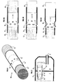
- the catalytic element 10 is shown in more detail in Figure 2 where we can see that it includes a ferrule 11 which surrounds the monolith itself. This comprises two catalytic elements 12, 13 separated by a vacuum 14. The empty volume 14 is thus delimited by a part of the shell 1 1 and by one face of each of the catalytic elements 12, 13.
- FIGs 3 and following relate to another embodiment of the invention which differs from the previous one in that the shell 11 comprises lights 15 at the empty volume 14.
- the shell 11 comprises lights 15 at the empty volume 14.
- part of the gases exhaust does not pass through the first catalytic element 12 since it arrives directly in the empty volume.
- This proportion of gases exhaust system cools the exhaust gases that have passed through the first catalytic element.
- FIGS 5A, 5B and 5C show variants of the invention.
- FIG. 5A illustrates an embodiment with lights 15 which occupy a large area; thus the gas penetration rate directly into volume 14 is relatively large.
- this permeability will be adapted to the envisaged flow.
- FIG. 5B shows curvatures around the openings 15, which allow to better direct the gas flow inside the shell 11, in the volume 14.
- the shell 11 has a specific profile with at least minus a circumferential groove 16 hollowed inwards. Groove 16 is located downstream of the openings 15 relative to the direction of circulation of the gas. This venturi type profile therefore makes it possible to accelerate the gases as soon as they introduction into volume 14 and / or promoting the mixing of the two flows gaseous.
- each element catalytic 12, 13 will be calculated to optimize the gas temperatures obtained at the output of each of them, in particular to avoid peaks of temperatures detrimental to their integrity.
- the distance between the monoliths can be defined so that obtain sufficient cooling of the gases leaving the first element catalytic 12 until the entry of the second 13, and to prevent again excessively high temperatures in the second catalytic element.
- Temperature, overall catalytic efficiency and ratio CO / HC emissions can be optimized by making holes on the ferrule 11, which allow part of the gas to bypass the first element catalytic 12.
- the number, size and shape of the orifices is adapt according to the proportion of gas that one wishes to deviate from first catalytic element 12.
- the internal wall of the empty volume 14 can be coated with a catalytic layer.
- This so-called "combi” concept allows gases to pass successively through a catalytic channel and then through a multi-channel honeycomb monolith, also with activity catalytic. This concept is very interesting for the treatment of gases during operating at low speed since it promotes the initiation of reactions catalytic.
- the catalyst element is located in the exhaust line silencer.
- Figure 6 partially shows a silencer that looks like the one shown schematically in Figure 3. The differences lie in the presence of a double envelope 4, 4 ′ delimiting an annular space 24 in which transits a fluid: air and / or exhaust gases. This fluid flows according to arrows B and enters volume 8 through holes 17 of the inner envelope 4.
- the catalytic element 10 here being provided with openings 15 located at the orifices 17, the fluid coming from the annular space 24 can flow into the empty volume 14 by venturi effect and then into the second monolith 13. This is particularly interesting in engines where the dynamic aspect is very important.
- the catalytic element can be integrated in a tubular zone of the exhaust line or even in the outlet of the diffuser.
- the preferred applications of the invention relate to engines 2 times of transport vehicles, but also lawn mowers, chainsaws, or other motorized vehicles.
Landscapes
- Chemical & Material Sciences (AREA)
- Engineering & Computer Science (AREA)
- Chemical Kinetics & Catalysis (AREA)
- Combustion & Propulsion (AREA)
- Mechanical Engineering (AREA)
- General Engineering & Computer Science (AREA)
- Health & Medical Sciences (AREA)
- Toxicology (AREA)
- Exhaust Gas After Treatment (AREA)
- Catalysts (AREA)
- Exhaust Gas Treatment By Means Of Catalyst (AREA)
Applications Claiming Priority (2)
| Application Number | Priority Date | Filing Date | Title |
|---|---|---|---|
| FR9802440 | 1998-02-27 | ||
| FR9802440A FR2775497B1 (fr) | 1998-02-27 | 1998-02-27 | Nouvel element catalytique destine au traitement des gaz d'echappement d'un moteur a combustion interne |
Publications (2)
| Publication Number | Publication Date |
|---|---|
| EP0939207A1 true EP0939207A1 (de) | 1999-09-01 |
| EP0939207B1 EP0939207B1 (de) | 2003-05-21 |
Family
ID=9523484
Family Applications (1)
| Application Number | Title | Priority Date | Filing Date |
|---|---|---|---|
| EP19990400418 Expired - Lifetime EP0939207B1 (de) | 1998-02-27 | 1999-02-22 | Neue katalytische Einheit zur Behandlung von Abgasen einer Brennkraftmaschine |
Country Status (4)
| Country | Link |
|---|---|
| EP (1) | EP0939207B1 (de) |
| JP (1) | JPH11294153A (de) |
| ES (1) | ES2200477T3 (de) |
| FR (1) | FR2775497B1 (de) |
Cited By (5)
| Publication number | Priority date | Publication date | Assignee | Title |
|---|---|---|---|---|
| EP1314865A3 (de) * | 2001-11-21 | 2004-01-28 | Cataler Corporation | Abgasreinigungsanlage |
| FR2856730A1 (fr) * | 2003-06-24 | 2004-12-31 | Jean Claude Fayard | Dispositif de postraitement de gaz d'echappement de moteur a allumage commande ou de bruleur par catalyse en deux etapes reduction puis oxydation |
| WO2015116979A3 (en) * | 2014-01-31 | 2015-10-22 | Donaldson Company, Inc. | Dosing and mixing arrangement for use in exhaust aftertreatment |
| WO2015172984A1 (de) * | 2014-05-16 | 2015-11-19 | Robert Bosch Gmbh | Verfahren und modulares system zum aufbau einer abgasnachbehandlungsvorrichtung |
| CN111788373A (zh) * | 2018-03-01 | 2020-10-16 | 纬湃技术有限公司 | 用于排气后处理的设备 |
Families Citing this family (3)
| Publication number | Priority date | Publication date | Assignee | Title |
|---|---|---|---|---|
| JP4922589B2 (ja) * | 2005-09-15 | 2012-04-25 | 川崎重工業株式会社 | 排気浄化装置 |
| DE102017101923A1 (de) * | 2017-02-01 | 2018-08-02 | Eberspächer Exhaust Technology GmbH & Co. KG | Abgasanlage |
| EP3346103B1 (de) | 2017-01-05 | 2019-05-22 | Eberspächer Exhaust Technology GmbH & Co. KG | Abgasanlage |
Citations (10)
| Publication number | Priority date | Publication date | Assignee | Title |
|---|---|---|---|---|
| US3796546A (en) | 1970-07-16 | 1974-03-12 | Peugeot | Exhaust gas purifying system for an internal combustion engine |
| GB2220150A (en) * | 1988-07-08 | 1990-01-04 | Piaggio & C Spa | Exhaust system with catalytic converter for two-stroke engines |
| JPH04140413A (ja) * | 1990-10-01 | 1992-05-14 | Yamaha Motor Co Ltd | 内燃機関の排気ガス浄化装置 |
| FR2687431A1 (fr) | 1992-02-14 | 1993-08-20 | Inst Francais Du Petrole | Tubulure d'echappement a paroi catalytique pour moteurs a combustion interne. |
| JPH05340234A (ja) * | 1992-06-05 | 1993-12-21 | Kubota Corp | エンジンの排気浄化消音装置 |
| US5285640A (en) * | 1992-07-21 | 1994-02-15 | Olivo John R | Integrated post-engine emissions heater, catalytic converter and muffler |
| EP0604992A1 (de) * | 1992-12-31 | 1994-07-06 | Firma J. Eberspächer | Abgasanlage für Verbrennungsmotoren |
| US5377486A (en) | 1993-05-17 | 1995-01-03 | Ford Motor Company | Catalytic converter system |
| EP0687806A1 (de) * | 1994-06-13 | 1995-12-20 | Showa Aircraft Industry Co., Ltd. | Metallträger für einen Katalysator |
| JPH08189344A (ja) | 1995-01-12 | 1996-07-23 | Fuji Oozx Inc | 排気ガスの浄化制御装置 |
Family Cites Families (2)
| Publication number | Priority date | Publication date | Assignee | Title |
|---|---|---|---|---|
| JPS6318123A (ja) * | 1986-07-10 | 1988-01-26 | Fuji Heavy Ind Ltd | 触媒コンバ−タ |
| US5033264A (en) * | 1989-06-16 | 1991-07-23 | Tecogen Inc. | Compact cogeneration system |
-
1998
- 1998-02-27 FR FR9802440A patent/FR2775497B1/fr not_active Expired - Fee Related
-
1999
- 1999-02-22 ES ES99400418T patent/ES2200477T3/es not_active Expired - Lifetime
- 1999-02-22 EP EP19990400418 patent/EP0939207B1/de not_active Expired - Lifetime
- 1999-03-01 JP JP11052750A patent/JPH11294153A/ja active Pending
Patent Citations (10)
| Publication number | Priority date | Publication date | Assignee | Title |
|---|---|---|---|---|
| US3796546A (en) | 1970-07-16 | 1974-03-12 | Peugeot | Exhaust gas purifying system for an internal combustion engine |
| GB2220150A (en) * | 1988-07-08 | 1990-01-04 | Piaggio & C Spa | Exhaust system with catalytic converter for two-stroke engines |
| JPH04140413A (ja) * | 1990-10-01 | 1992-05-14 | Yamaha Motor Co Ltd | 内燃機関の排気ガス浄化装置 |
| FR2687431A1 (fr) | 1992-02-14 | 1993-08-20 | Inst Francais Du Petrole | Tubulure d'echappement a paroi catalytique pour moteurs a combustion interne. |
| JPH05340234A (ja) * | 1992-06-05 | 1993-12-21 | Kubota Corp | エンジンの排気浄化消音装置 |
| US5285640A (en) * | 1992-07-21 | 1994-02-15 | Olivo John R | Integrated post-engine emissions heater, catalytic converter and muffler |
| EP0604992A1 (de) * | 1992-12-31 | 1994-07-06 | Firma J. Eberspächer | Abgasanlage für Verbrennungsmotoren |
| US5377486A (en) | 1993-05-17 | 1995-01-03 | Ford Motor Company | Catalytic converter system |
| EP0687806A1 (de) * | 1994-06-13 | 1995-12-20 | Showa Aircraft Industry Co., Ltd. | Metallträger für einen Katalysator |
| JPH08189344A (ja) | 1995-01-12 | 1996-07-23 | Fuji Oozx Inc | 排気ガスの浄化制御装置 |
Non-Patent Citations (2)
| Title |
|---|
| PATENT ABSTRACTS OF JAPAN vol. 016, no. 416 (M - 1304) 2 September 1992 (1992-09-02) * |
| PATENT ABSTRACTS OF JAPAN vol. 018, no. 183 (M - 1584) 29 March 1994 (1994-03-29) * |
Cited By (10)
| Publication number | Priority date | Publication date | Assignee | Title |
|---|---|---|---|---|
| EP1314865A3 (de) * | 2001-11-21 | 2004-01-28 | Cataler Corporation | Abgasreinigungsanlage |
| US7048895B2 (en) | 2001-11-21 | 2006-05-23 | Cataler Corporation | Exhaust gas purifying apparatus |
| FR2856730A1 (fr) * | 2003-06-24 | 2004-12-31 | Jean Claude Fayard | Dispositif de postraitement de gaz d'echappement de moteur a allumage commande ou de bruleur par catalyse en deux etapes reduction puis oxydation |
| WO2015116979A3 (en) * | 2014-01-31 | 2015-10-22 | Donaldson Company, Inc. | Dosing and mixing arrangement for use in exhaust aftertreatment |
| US9528415B2 (en) | 2014-01-31 | 2016-12-27 | Donaldson Company, Inc. | Dosing and mixing arrangement for use in exhaust aftertreatment |
| US10030562B2 (en) | 2014-01-31 | 2018-07-24 | Donaldson Company, Inc. | Dosing and mixing arrangement for use in exhaust aftertreatment |
| US10844764B2 (en) | 2014-01-31 | 2020-11-24 | Donaldson Company, Inc. | Dosing and mixing arrangement for use in exhaust aftertreatment |
| WO2015172984A1 (de) * | 2014-05-16 | 2015-11-19 | Robert Bosch Gmbh | Verfahren und modulares system zum aufbau einer abgasnachbehandlungsvorrichtung |
| CN111788373A (zh) * | 2018-03-01 | 2020-10-16 | 纬湃技术有限公司 | 用于排气后处理的设备 |
| CN111788373B (zh) * | 2018-03-01 | 2022-05-31 | 纬湃技术有限公司 | 用于排气后处理的设备 |
Also Published As
| Publication number | Publication date |
|---|---|
| FR2775497A1 (fr) | 1999-09-03 |
| ES2200477T3 (es) | 2004-03-01 |
| JPH11294153A (ja) | 1999-10-26 |
| EP0939207B1 (de) | 2003-05-21 |
| FR2775497B1 (fr) | 2000-05-05 |
Similar Documents
| Publication | Publication Date | Title |
|---|---|---|
| WO2012052672A1 (fr) | Ligne d'échappement pour véhicule automobile. | |
| EP2686529B1 (de) | Kompakte gekrümmte einheit zur nachbehandlung von abgasen, antriebsstrang und zugehöriges fahrzeug | |
| EP2676016B1 (de) | Abgasnachbehandlungsbaugruppe für einen verbrennungsmotor und krafftahrzeug mit einer solchen baugruppe | |
| EP2551482B1 (de) | Bogenförmige Anordnung zur Nachbehandlung der Abgase eines Verbrennungsmotors, die ein internes Einlaufrohr umfasst | |
| WO2010146285A1 (fr) | Ligne d'échappement avec système d'injection | |
| FR2842247A1 (fr) | Systeme de commande des emissions d'echappement d'un moteur a combustion interne | |
| EP0939207B1 (de) | Neue katalytische Einheit zur Behandlung von Abgasen einer Brennkraftmaschine | |
| FR2540177A1 (fr) | Regeneration des filtres catalytiques a particules et appareil pour sa mise en oeuvre | |
| FR2928176A1 (fr) | Procede de regeneration d'un filtre a particules pour moteur a essence et ensemble d'echappement associe | |
| FR2902137A1 (fr) | Bruleur et procede pour la regeneration de cartouches de filtration et dispositifs equipes d'un tel bruleur | |
| EP0166480B1 (de) | Schalldämpfender und gasreinigender Auspufftopf, insbesondere für Verbrennungsmotoren | |
| EP0718478B1 (de) | Abgasbehandlungsvorrichtung einer Dieselbrennkraftmaschine mit einem Katalysator und einem Stickoxydenadsorber, die in Abgaskrümmer angeordnet sind | |
| FR3081921A1 (fr) | Ligne d’echappement de moteur thermique comprenant un element de chauffage amont | |
| EP2163743B1 (de) | Verfahren zur Behandlung von Schadstoffe, die in den Abgasen eines Verbrennungsmotors enthalten sind | |
| FR2819549A1 (fr) | Systeme de traitement des gaz d'echappement d'un moteur a combustion | |
| FR3037101A1 (fr) | Ligne d’echappement d’un moteur thermique | |
| FR3107554A1 (fr) | Système de depollution des gaz d’echappement d’un moteur essence | |
| EP1015741B1 (de) | Methode zur abgasbehandlung einer brennkraftmaschine und zugehörige auspuffleitung | |
| EP1672194B1 (de) | Verfahren zur Regeneration eines Partikelfilters mit einer katalytischen Verbrennungseinheit und das Verfahren verwendende Filtervorrichtung | |
| FR3147588A1 (fr) | Conduit d’échappement d’un banc d’essai de turbine avec double tube | |
| FR3107729A1 (fr) | Ligne d’échappement | |
| FR2939471A3 (fr) | Ligne d'echappement comportant un module de rechauffement des gaz d'echappement suivi d'un systeme de post-traitement des gaz d'echappement | |
| FR2878898A1 (fr) | Filtre d'epuration de gaz d'echappement et procede de fabrication de celui-ci | |
| FR2870566A1 (fr) | Dispositif et procede de traitement des gaz d'echappement d'un moteur a combustion interne suralimente en vue de leur depollution | |
| EP0806554A1 (de) | Auspuffanlage für Brennkraftmaschine |
Legal Events
| Date | Code | Title | Description |
|---|---|---|---|
| PUAI | Public reference made under article 153(3) epc to a published international application that has entered the european phase |
Free format text: ORIGINAL CODE: 0009012 |
|
| AK | Designated contracting states |
Kind code of ref document: A1 Designated state(s): BE ES FR GB IT |
|
| AX | Request for extension of the european patent |
Free format text: AL;LT;LV;MK;RO;SI |
|
| 17P | Request for examination filed |
Effective date: 20000301 |
|
| AKX | Designation fees paid |
Free format text: BE ES FR GB IT |
|
| REG | Reference to a national code |
Ref country code: DE Ref legal event code: 8566 |
|
| 17Q | First examination report despatched |
Effective date: 20010511 |
|
| GRAH | Despatch of communication of intention to grant a patent |
Free format text: ORIGINAL CODE: EPIDOS IGRA |
|
| GRAH | Despatch of communication of intention to grant a patent |
Free format text: ORIGINAL CODE: EPIDOS IGRA |
|
| GRAA | (expected) grant |
Free format text: ORIGINAL CODE: 0009210 |
|
| AK | Designated contracting states |
Designated state(s): BE ES FR GB IT |
|
| REG | Reference to a national code |
Ref country code: GB Ref legal event code: FG4D Free format text: NOT ENGLISH |
|
| GBT | Gb: translation of ep patent filed (gb section 77(6)(a)/1977) |
Effective date: 20030521 |
|
| PGFP | Annual fee paid to national office [announced via postgrant information from national office to epo] |
Ref country code: BE Payment date: 20040223 Year of fee payment: 6 |
|
| REG | Reference to a national code |
Ref country code: ES Ref legal event code: FG2A Ref document number: 2200477 Country of ref document: ES Kind code of ref document: T3 |
|
| PLBE | No opposition filed within time limit |
Free format text: ORIGINAL CODE: 0009261 |
|
| STAA | Information on the status of an ep patent application or granted ep patent |
Free format text: STATUS: NO OPPOSITION FILED WITHIN TIME LIMIT |
|
| 26N | No opposition filed |
Effective date: 20040224 |
|
| PG25 | Lapsed in a contracting state [announced via postgrant information from national office to epo] |
Ref country code: BE Free format text: LAPSE BECAUSE OF NON-PAYMENT OF DUE FEES Effective date: 20050228 |
|
| BERE | Be: lapsed |
Owner name: S.A. *ROSI Effective date: 20050228 Owner name: INSTITUT FRANCAIS DU *PETROLE Effective date: 20050228 |
|
| BERE | Be: lapsed |
Owner name: S.A. *ROSI Effective date: 20050228 Owner name: INSTITUT FRANCAIS DU *PETROLE Effective date: 20050228 |
|
| REG | Reference to a national code |
Ref country code: FR Ref legal event code: CD |
|
| PGFP | Annual fee paid to national office [announced via postgrant information from national office to epo] |
Ref country code: IT Payment date: 20110219 Year of fee payment: 13 Ref country code: FR Payment date: 20110127 Year of fee payment: 13 |
|
| PGFP | Annual fee paid to national office [announced via postgrant information from national office to epo] |
Ref country code: ES Payment date: 20110225 Year of fee payment: 13 Ref country code: GB Payment date: 20110224 Year of fee payment: 13 |
|
| GBPC | Gb: european patent ceased through non-payment of renewal fee |
Effective date: 20120222 |
|
| REG | Reference to a national code |
Ref country code: FR Ref legal event code: ST Effective date: 20121031 |
|
| PG25 | Lapsed in a contracting state [announced via postgrant information from national office to epo] |
Ref country code: IT Free format text: LAPSE BECAUSE OF NON-PAYMENT OF DUE FEES Effective date: 20120222 |
|
| PG25 | Lapsed in a contracting state [announced via postgrant information from national office to epo] |
Ref country code: GB Free format text: LAPSE BECAUSE OF NON-PAYMENT OF DUE FEES Effective date: 20120222 Ref country code: FR Free format text: LAPSE BECAUSE OF NON-PAYMENT OF DUE FEES Effective date: 20120229 |
|
| REG | Reference to a national code |
Ref country code: ES Ref legal event code: FD2A Effective date: 20130709 |
|
| PG25 | Lapsed in a contracting state [announced via postgrant information from national office to epo] |
Ref country code: ES Free format text: LAPSE BECAUSE OF NON-PAYMENT OF DUE FEES Effective date: 20120223 |