EP0940321A1 - Chassis pour véhicule utilitaire lourd - Google Patents
Chassis pour véhicule utilitaire lourd Download PDFInfo
- Publication number
- EP0940321A1 EP0940321A1 EP99101607A EP99101607A EP0940321A1 EP 0940321 A1 EP0940321 A1 EP 0940321A1 EP 99101607 A EP99101607 A EP 99101607A EP 99101607 A EP99101607 A EP 99101607A EP 0940321 A1 EP0940321 A1 EP 0940321A1
- Authority
- EP
- European Patent Office
- Prior art keywords
- rigid axle
- strut
- chassis according
- axle body
- axle
- Prior art date
- Legal status (The legal status is an assumption and is not a legal conclusion. Google has not performed a legal analysis and makes no representation as to the accuracy of the status listed.)
- Granted
Links
Images


Classifications
-
- B—PERFORMING OPERATIONS; TRANSPORTING
- B62—LAND VEHICLES FOR TRAVELLING OTHERWISE THAN ON RAILS
- B62D—MOTOR VEHICLES; TRAILERS
- B62D33/00—Superstructures for load-carrying vehicles
- B62D33/06—Drivers' cabs
- B62D33/063—Drivers' cabs movable from one position into at least one other position, e.g. tiltable, pivotable about a vertical axis, displaceable from one side of the vehicle to the other
- B62D33/067—Drivers' cabs movable from one position into at least one other position, e.g. tiltable, pivotable about a vertical axis, displaceable from one side of the vehicle to the other tiltable
-
- B—PERFORMING OPERATIONS; TRANSPORTING
- B60—VEHICLES IN GENERAL
- B60G—VEHICLE SUSPENSION ARRANGEMENTS
- B60G9/00—Resilient suspensions of a rigid axle or axle housing for two or more wheels
-
- B—PERFORMING OPERATIONS; TRANSPORTING
- B62—LAND VEHICLES FOR TRAVELLING OTHERWISE THAN ON RAILS
- B62D—MOTOR VEHICLES; TRAILERS
- B62D21/00—Understructures, i.e. chassis frame on which a vehicle body may be mounted
- B62D21/11—Understructures, i.e. chassis frame on which a vehicle body may be mounted with resilient means for suspension, e.g. of wheels or engine; sub-frames for mounting engine or suspensions
-
- B—PERFORMING OPERATIONS; TRANSPORTING
- B62—LAND VEHICLES FOR TRAVELLING OTHERWISE THAN ON RAILS
- B62D—MOTOR VEHICLES; TRAILERS
- B62D25/00—Superstructure or monocoque structure sub-units; Parts or details thereof not otherwise provided for
- B62D25/08—Front or rear portions
- B62D25/088—Details of structures as upper supports for springs or dampers
-
- B—PERFORMING OPERATIONS; TRANSPORTING
- B60—VEHICLES IN GENERAL
- B60G—VEHICLE SUSPENSION ARRANGEMENTS
- B60G2206/00—Indexing codes related to the manufacturing of suspensions: constructional features, the materials used, procedures or tools
- B60G2206/01—Constructional features of suspension elements, e.g. arms, dampers, springs
- B60G2206/60—Subframe construction
- B60G2206/602—Single transverse beam
-
- B—PERFORMING OPERATIONS; TRANSPORTING
- B60—VEHICLES IN GENERAL
- B60G—VEHICLE SUSPENSION ARRANGEMENTS
- B60G2300/00—Indexing codes relating to the type of vehicle
- B60G2300/14—Buses
Definitions
- the invention relates to a chassis of a heavy commercial vehicle with features according to the preamble of claim 1.
- the U-shaped cross member Due to the provision of the U-shaped cross member according to the invention results a correspondingly stabilized frame section as well as in the area of the rigid axle a large free space between the frame side members and above the lower one Cross member cross section, which there the unimpeded installation of other vehicle parts, like a drive unit in a truck or a middle aisle in an omnibus.
- the fixed connection of two trailing arms to the rigid axle beam results in a component assembly that is easily attached to the frame Bearing blocks are articulated and with regard to the suspension and damping elements allows different versions.
- the rigid axle trailing arm assembly makes it possible that a Panhard rod is sufficient for lateral guidance, for the axle-side connection point on the rigid axle-trailing arm assembly according to the invention and the frame-side junction on the U-shaped Cross member is provided. Its advantage is also that it with its lower cross section, with which it extends over the rigid axle beam and the Panhard rod extends, the two side sections so stabilizing each other connects that the frame side members are stabilized.
- the side sections of the U-shaped cross member to represent by strut bracket and struts with air or Coil spring and coaxial shock absorber as spring / damper elements to use, which is a novelty in a heavy commercial vehicle.
- the connection of these struts at the top of such a strut holder and at the bottom at a pivot point on the rigid axle body, in particular as claimed 6 indicated, provides a very high driving and suspension comfort when driving.
- the chassis according to the invention is part of a heavy commercial vehicle, which is a truck, especially the front-link design tilting cab, with attachments and superstructures of various types, including those trade for special purposes, a tractor unit or an omnibus can.
- the invention can generally be used in connection with a rigid axle come, which is a front axle, trailing axle or leading axle can act with steerable or non-steerable wheels.
- a rigid axle come which is a front axle, trailing axle or leading axle can act with steerable or non-steerable wheels.
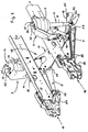
- the rigid axle according to the invention is shown as the front axle. From the chassis are in the drawing as parts of the frame whose two longitudinal beams with 1 and 2 designated.
- the rigid axle shown includes all suspension, Suspension and damping elements from the following main parts, namely a rigid axle body 3, a left trailing arm 4 and right trailing arm 5, a left Suspension strut 6 with air or coil spring 7 and coaxial shock absorber 8 for this purpose, a right shock absorber 9 with air or coil spring 10 and this coaxial Shock absorber 11, a U-shaped cross member 38 seen from the front and one Panhard staff 15.
- Each of them is outside on one Frame side members 1 and 2 attached and used for frame-side articulation of the rigid axle according to the invention and in the present example also beyond as a had, support and storage organ for a larger number of vehicle parts to be attached.
- the rigid axle body 3 has a straight central region 18 and the same on both sides subsequent end sections 19, 20 cranked up in the example shown on.
- At the transition area between the straight central area 18 and each end section 19, 20 is on the front - in the case of a drawn axle in the front and in the case of one pushed axis at the rear - on the rigid axle body 3 each an extension or projection with post-machined contact surface 21 or 22, on each one of the two trailing arms 4, 5 with its foot 23 or 24 on the axle body side is non-positively and if necessary also flange-mounted.
- the Contact surface 21 or 22 preferably extends over a large width the entire height available on the rigid axle body 3 in order to have a height on the rigid axle body 3 to provide the largest possible connection base for the respective trailing arm 4 or 5.
- 5 several screws 25, z. B. 4 pieces each, provided by the opposite side of the rigid axle beam 3 ago through through holes formed in this as well as in aligned blind hole threaded holes in the respective trailing arm base 23 or 24 are screwed in, with a high preload and such ensured that the rigid axle-trailing link assembly at all in driving occurring loads are perfectly preserved.
- This construction leaves it in advantageously, the rigid axle in the manner of a self-stabilizing torsion beam axle to design.
- This function and purpose is obeyed hence the rigid axle body 3 in its straight central region 18 between the two trailing arms 4, 5 connected to it are designed to be torsionally defined.
- the straight or - as shown in the drawing - Rigid axle body 3 formed in the manner of a cranked fist axis made by forging or casting and then at certain points machined or finished.
- the profile and size of the cross section its central area 18 are in the sense of the desired torsional ability tailored to the respective vehicle-specific application.
- trailing arms 4, 5 connected to it Stabilizer function integrated and trained accordingly. They are each as a cast part, possibly also forged part and then machined or finished in certain places, also in the vertical comparatively rigid, but can be twisted to a limited extent about its longitudinal axis.
- the two trailing arms 4, 5 are in this case with regard to their Bending stiffness and torsional ability related to the overall stabilizing effect matched with the torsional rigid axle body 3, by appropriate dimensioning and shaping of their cross sections.
- each of the two equally long trailing arms 4, 5 has between them Foot 23 or 24 and another existing bearing eye 26 or 27 one rod-shaped area with a size that changes over the length the bearing eye 26 or 27 towards a cross section that becomes smaller.
- the two trailing arms 4, 5 mirror-symmetrical to the longitudinal axis of the vehicle and - viewed from above - such Arrows standing connected to each other on the rigid axle body 3 that they enclose a trapezoidal surface, the distance between their bearing eyes 26 and 27, with which they are attached to the multi-functional bearing shields attached to the frame 16 and 17 are articulated, is smaller than the distance between their axles Feet 23 or 24 when the rigid axle according to the invention installed in the vehicle is, the two trailing arms 4, 5 - viewed from the side - run from Rigid axle body 3 directed obliquely upwards to the frame side Multifunction end shields 16 and 17 out.
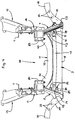
- the cross member 38 has two side sections and a lower one Cross section with which he the rigid axle body 3 and the Panhard rod 15th bridged at the top with a small distance.
- the cross member 38 connects the two Frame side members 1, 2 stabilizing each other and is on this with his Side sections attached.
- the two Suspension strut brackets 12, 13 are used to hold and support one on each axle side provided strut 6 or 9.
- struts 6, 9 By using such struts 6, 9 a very high driving and suspension comfort can be achieved in driving operation. This achieves an optimum when the largest possible spring track is determined that is, each of the two struts 6 and 9 at its lower end z.
- axle body-fixed bearing is articulated, which is spatially in the area between a trailing arm 4 or 5 and an adjacent axle end wheel carrier connection head 34 or 35 arranged as far as possible towards the latter and by means of a mouth-like part attached to or molded onto the rigid axle body 3 Bock 32 or 33 is formed.
- the crossbeam is inside the U-shaped crossbeam 38 14 by a pressed sheet metal part in cross section, optionally also Forged or cast part, formed that a straight central section 39 and on both sides it each has an obliquely raised end section 40 or 41.
- Its outer ends are designed in the manner of a mouth with which the one to be connected Suspension strut bracket 12 or 13 is gripped on the outside. Every mouth will through a cutout 42 or 43 in the upper flange of the crossbar 14 and on both sides each cutout 42 or 43 remaining cheeks 44, 45 or 46, 47 formed, which associated contact surfaces on the respective spring retainer 12 or 13 at the front and rear 48, 49 and 50, 51 are assigned.
- the crossbar 14 In the area of these contact surfaces 48, 49 or 50, 51, the crossbar 14 is supported with its cheeks 44, 45 and 46, 47 and there through corresponding bores or holes 52 penetrating screws 53 firmly connected to the respective strut holder 12 or 13. In the middle of its upper flange, the crossbar 14 can be used to reduce weight have multiple breakthroughs.
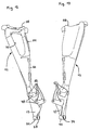
- each strut holder 12 or 13 is what his As far as shape is concerned, at least in its upper area in the manner of an exterior open half-shell 54 and 55 formed, from the boundary wall 56th or 57 the associated strut 6 or 9 in the area of its air or coil spring 7 or 10 partially covered radially outside with a small distance from the inside is and on the head plate 58 and 59, the respective strut 6 and 9 at the top supported and by means of two holes 60 or 61 penetrating screw connections 62 or 63 is attached.
- a central hole 64 or 65 in the strut head plate 58 or 59 is used to center the respective shock absorber 12 or 13 and free passage from its upper end 36 or 37.
- Each suspension strut bracket 12 or 13 has a height range on the outside of the half-shell 54 or 55 then a connecting flange 66 or 67 with several Screw holes 68 and 69 on.
- the respective connection flange 66 or 67 which is given approximately in the center of thrust, is each of the two strut holders 12 or 13 flanged to the outside of the associated frame side member 1 or 2 and there in each case by means of a plurality of holes 68 and 69, respectively, which are aligned within the longitudinal member Holes penetrating screws 70 attached with associated nuts.
- Different openings 71 and 72 in the strut holders 12 and 13 serve to reduce their weight.
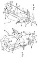
- the frame-side connection point for one end of the Panhard rod 15 is according to the invention provided on the cross member 38.
- this is one of the two strut brackets 12 and 13 beyond its actual function
- Another function is imprinted, namely that of the support, holding and articulation element to form one end of the Panhard rod 15.
- the relevant shock absorber bracket 12 or 13 extended downwards by a bearing plate 73, at its lower end a mouth and on both sides of it a bearing eye 74 and 75 are formed, on which the Panhard rod 15 via a in its one end bearing eye 76 built-in claw joint 77 supported and by means of Screws 78 is attached.
- the axle-side articulation point for the opposite other end of the Panhard rod 15 is, according to the invention, on the rigid axle-longitudinal link assembly 3, 4, 5 intended.
- the Panhard rod 15 z. B. in the bearing eye 79th built-in claw joint 80, with which he at a suitable point of the rigid axle-trailing arm assembly 3, 4, 5 is articulated.
- Rigid axle body 3 is either attached to or attached to a connecting block, on which a corresponding contact surface and threaded holes for screwing of the claw joint 80 are worked on.
- the two multifunction end shields 16, 17 each have one towards the center of the vehicle protruding projection 83 or 84, in the interior of which is free from the outside there is a pivot point for the rigid axle, in the form of a contact surface and a transverse bore 85 into which the front trailing arm bearing eye is installed 26 or 27 penetrating bearing bolts installed and then each of these two bearings from the outside by means of several Screws 86 secured to multifunction bearing plate 16 or 17 attached cover 87 becomes.
Landscapes
- Engineering & Computer Science (AREA)
- Mechanical Engineering (AREA)
- Chemical & Material Sciences (AREA)
- Combustion & Propulsion (AREA)
- Transportation (AREA)
- Vehicle Body Suspensions (AREA)
Applications Claiming Priority (2)
| Application Number | Priority Date | Filing Date | Title |
|---|---|---|---|
| DE19809203A DE19809203A1 (de) | 1998-03-04 | 1998-03-04 | Fahrgestell eines schweren Nutzfahrzeuges |
| DE19809203 | 1998-03-04 |
Publications (2)
| Publication Number | Publication Date |
|---|---|
| EP0940321A1 true EP0940321A1 (fr) | 1999-09-08 |
| EP0940321B1 EP0940321B1 (fr) | 2003-05-02 |
Family
ID=7859662
Family Applications (1)
| Application Number | Title | Priority Date | Filing Date |
|---|---|---|---|
| EP99101607A Expired - Lifetime EP0940321B1 (fr) | 1998-03-04 | 1999-02-03 | Chassis pour véhicule utilitaire lourd |
Country Status (2)
| Country | Link |
|---|---|
| EP (1) | EP0940321B1 (fr) |
| DE (2) | DE19809203A1 (fr) |
Cited By (2)
| Publication number | Priority date | Publication date | Assignee | Title |
|---|---|---|---|---|
| WO2007062744A1 (fr) | 2005-12-01 | 2007-06-07 | Volvo Lastvagnar Ab | Barre stabilisatrice pour vehicules a moteur |
| CN110789623A (zh) * | 2019-12-10 | 2020-02-14 | 诸城航大新材料技术有限公司 | 一种扭杆式铝合金翻转支座结构 |
Families Citing this family (1)
| Publication number | Priority date | Publication date | Assignee | Title |
|---|---|---|---|---|
| DE102014202831A1 (de) * | 2014-02-17 | 2015-08-20 | Daf Trucks N.V. | Fahrwerkanordnung für ein Kraftfahrzeug |
Citations (6)
| Publication number | Priority date | Publication date | Assignee | Title |
|---|---|---|---|---|
| US4168086A (en) * | 1977-08-01 | 1979-09-18 | Dana Corporation | Radius arm support for a driving axle |
| DE4226500A1 (de) * | 1992-08-11 | 1994-02-17 | Daimler Benz Ag | Anschlußknoten |
| EP0636531A2 (fr) * | 1993-07-27 | 1995-02-01 | Nissan Motor Co., Ltd. | Structure de véhicule |
| EP0678405A2 (fr) * | 1994-04-18 | 1995-10-25 | Mercedes-Benz Ag | Partie avant d'autobus comprenant un élément porteur pour suspensions élastiques |
| US5641181A (en) * | 1995-03-23 | 1997-06-24 | Ford Motor Company | Cross member for a vehicle having rack and pinion steering |
| DE19624242A1 (de) * | 1996-06-18 | 1997-09-18 | Daimler Benz Ag | Vorrichtung zur Querführung einer Starrachse eines Kraftfahrzeuges |
Family Cites Families (12)
| Publication number | Priority date | Publication date | Assignee | Title |
|---|---|---|---|---|
| FR1226451A (fr) * | 1959-01-13 | 1960-07-13 | Simca Automobiles Sa | Soubassement pour véhicule automobile |
| US3951225A (en) * | 1969-12-12 | 1976-04-20 | Kurt Schwenk | Torsion axle for motor vehicles |
| US4386792A (en) * | 1978-10-04 | 1983-06-07 | Ford Motor Company | Fabricated load support structural member |
| IT1197358B (it) * | 1986-10-07 | 1988-11-30 | Pirelli Accessori Ind | Dispositivo di sospensione per autoveicoli |
| FR2662118A1 (fr) * | 1990-05-17 | 1991-11-22 | Peugeot | Train arriere d'un vehicule automobile. |
| DE4107303C2 (de) * | 1991-03-07 | 1994-02-17 | Man Nutzfahrzeuge Ag | Luftgefederte, lenkbare Räder tragende Achse eines Kraftfahrzeuges, insbesondere Niederflurbus |
| JP3079791B2 (ja) * | 1992-09-11 | 2000-08-21 | 日産自動車株式会社 | 車両用アクスルビーム式サスペンションの配設構造 |
| US5636857A (en) * | 1995-03-06 | 1997-06-10 | Ford Motor Company | Vehicle solid axle front suspension system |
| DE4329862A1 (de) * | 1993-09-03 | 1995-03-09 | Hotzenblitz Mobile Gmbh Co Kg | Hinterachse für Kraftfahrzeuge |
| DE19704821A1 (de) * | 1996-02-21 | 1997-08-28 | Volkswagen Ag | Einzelradaufhängung für ein Kraftfahrzeug |
| DE19649076B4 (de) * | 1996-11-27 | 2006-10-05 | Benteler Ag | Verfahren zur Herstellung einer Verbundlenkerachse für Kraftfahrzeuge und Verbundlenkerachse |
| DE29720207U1 (de) * | 1997-11-14 | 1998-01-02 | Benteler Ag, 33104 Paderborn | Verbundlenkerachse für Kraftfahrzeuge |
-
1998
- 1998-03-04 DE DE19809203A patent/DE19809203A1/de not_active Withdrawn
-
1999
- 1999-02-03 DE DE59905272T patent/DE59905272D1/de not_active Expired - Lifetime
- 1999-02-03 EP EP99101607A patent/EP0940321B1/fr not_active Expired - Lifetime
Patent Citations (6)
| Publication number | Priority date | Publication date | Assignee | Title |
|---|---|---|---|---|
| US4168086A (en) * | 1977-08-01 | 1979-09-18 | Dana Corporation | Radius arm support for a driving axle |
| DE4226500A1 (de) * | 1992-08-11 | 1994-02-17 | Daimler Benz Ag | Anschlußknoten |
| EP0636531A2 (fr) * | 1993-07-27 | 1995-02-01 | Nissan Motor Co., Ltd. | Structure de véhicule |
| EP0678405A2 (fr) * | 1994-04-18 | 1995-10-25 | Mercedes-Benz Ag | Partie avant d'autobus comprenant un élément porteur pour suspensions élastiques |
| US5641181A (en) * | 1995-03-23 | 1997-06-24 | Ford Motor Company | Cross member for a vehicle having rack and pinion steering |
| DE19624242A1 (de) * | 1996-06-18 | 1997-09-18 | Daimler Benz Ag | Vorrichtung zur Querführung einer Starrachse eines Kraftfahrzeuges |
Cited By (2)
| Publication number | Priority date | Publication date | Assignee | Title |
|---|---|---|---|---|
| WO2007062744A1 (fr) | 2005-12-01 | 2007-06-07 | Volvo Lastvagnar Ab | Barre stabilisatrice pour vehicules a moteur |
| CN110789623A (zh) * | 2019-12-10 | 2020-02-14 | 诸城航大新材料技术有限公司 | 一种扭杆式铝合金翻转支座结构 |
Also Published As
| Publication number | Publication date |
|---|---|
| DE19809203A1 (de) | 1999-09-09 |
| EP0940321B1 (fr) | 2003-05-02 |
| DE59905272D1 (de) | 2003-06-05 |
Similar Documents
| Publication | Publication Date | Title |
|---|---|---|
| EP0940272B1 (fr) | Chassis pour un camion à cabine avancée | |
| DE102013108695B4 (de) | Hilfsrahmen für eine Kraftfahrzeugachse | |
| DE10219275B4 (de) | Fahrgestell für ein Nutzfahrzeug | |
| DE102004028161B4 (de) | Unterfahrschutz für Personenkraftfahrzeuge zur Anordnung unter Längsträgerniveau vor einem Hilfsrahmen oder Achsträger als zusätzliche Crashebene | |
| WO2007031060A1 (fr) | Support d'essieu avant destine en particulier a des vehicules | |
| EP1318064B1 (fr) | Châssis modulaire pour un camion | |
| DE102009042060A1 (de) | Strukturbauteil für Hinterrahmenstruktur eines Kraftfahrzeugs | |
| EP0940320B1 (fr) | Chassis pour véhicule utilitaire lourd | |
| EP1154908B1 (fr) | Suspension pour essieu rigide de vehicule | |
| EP0940319B1 (fr) | Chassis d'un véhicule utilitaire lourd | |
| EP2114753A1 (fr) | Support d'essieu pour véhicules automobiles | |
| WO2014009320A1 (fr) | Bras de suspension de roue et groupe d'essieu pour un essieu non mené d'un véhicule, notamment d'un véhicule utilitaire | |
| DE69426991T2 (de) | Längsarmaufhängung | |
| EP0940324B1 (fr) | Chassis pour véhicule utilitaire lourd | |
| EP0940325B1 (fr) | Chassis pour véhicule utilitaire lourd | |
| EP0940322B1 (fr) | Chassis pour véhicule utilitaire lourd | |
| EP0940321B1 (fr) | Chassis pour véhicule utilitaire lourd | |
| EP0940323B1 (fr) | Chassis pour véhicule utilitaire lourd | |
| EP3929065B1 (fr) | Châssis de montage | |
| DE202015102551U1 (de) | Achsanordnung | |
| DE102015004858A1 (de) | Lenker für Starrachsen von Nutzfahrzeugen | |
| EP0591719B1 (fr) | Véhicule utilitaire, notamment un camion à cabine avancée | |
| DE102018006572B4 (de) | Fahrzeugaufhängungsanordnung für mindestens eine Radachse | |
| DE20011858U1 (de) | Achsbock für Fahrzeuge, insbesondere Kraftfahrzeuge | |
| EP1447247A2 (fr) | Suspension à essieu rigide pour un véhicule |
Legal Events
| Date | Code | Title | Description |
|---|---|---|---|
| PUAI | Public reference made under article 153(3) epc to a published international application that has entered the european phase |
Free format text: ORIGINAL CODE: 0009012 |
|
| 17P | Request for examination filed |
Effective date: 19990714 |
|
| AK | Designated contracting states |
Kind code of ref document: A1 Designated state(s): DE FR IT NL SE |
|
| AX | Request for extension of the european patent |
Free format text: AL;LT;LV;MK;RO;SI |
|
| AKX | Designation fees paid |
Free format text: DE FR IT NL SE |
|
| 17Q | First examination report despatched |
Effective date: 20010716 |
|
| GRAG | Despatch of communication of intention to grant |
Free format text: ORIGINAL CODE: EPIDOS AGRA |
|
| GRAG | Despatch of communication of intention to grant |
Free format text: ORIGINAL CODE: EPIDOS AGRA |
|
| GRAH | Despatch of communication of intention to grant a patent |
Free format text: ORIGINAL CODE: EPIDOS IGRA |
|
| GRAH | Despatch of communication of intention to grant a patent |
Free format text: ORIGINAL CODE: EPIDOS IGRA |
|
| GRAA | (expected) grant |
Free format text: ORIGINAL CODE: 0009210 |
|
| AK | Designated contracting states |
Designated state(s): DE FR IT NL SE |
|
| REF | Corresponds to: |
Ref document number: 59905272 Country of ref document: DE Date of ref document: 20030605 Kind code of ref document: P |
|
| REG | Reference to a national code |
Ref country code: SE Ref legal event code: TRGR |
|
| ET | Fr: translation filed | ||
| PLBE | No opposition filed within time limit |
Free format text: ORIGINAL CODE: 0009261 |
|
| STAA | Information on the status of an ep patent application or granted ep patent |
Free format text: STATUS: NO OPPOSITION FILED WITHIN TIME LIMIT |
|
| 26N | No opposition filed |
Effective date: 20040203 |
|
| REG | Reference to a national code |
Ref country code: NL Ref legal event code: TD Effective date: 20110420 |
|
| REG | Reference to a national code |
Ref country code: FR Ref legal event code: CD |
|
| REG | Reference to a national code |
Ref country code: DE Ref legal event code: R081 Ref document number: 59905272 Country of ref document: DE Owner name: MAN TRUCK & BUS AG, DE Free format text: FORMER OWNER: MAN NUTZFAHRZEUGE AG, 80995 MUENCHEN, DE Effective date: 20110518 |
|
| REG | Reference to a national code |
Ref country code: FR Ref legal event code: PLFP Year of fee payment: 18 |
|
| REG | Reference to a national code |
Ref country code: FR Ref legal event code: PLFP Year of fee payment: 19 |
|
| REG | Reference to a national code |
Ref country code: FR Ref legal event code: PLFP Year of fee payment: 20 |
|
| PGFP | Annual fee paid to national office [announced via postgrant information from national office to epo] |
Ref country code: NL Payment date: 20180223 Year of fee payment: 20 |
|
| PGFP | Annual fee paid to national office [announced via postgrant information from national office to epo] |
Ref country code: IT Payment date: 20180221 Year of fee payment: 20 Ref country code: SE Payment date: 20180227 Year of fee payment: 20 Ref country code: FR Payment date: 20180227 Year of fee payment: 20 |
|
| PGFP | Annual fee paid to national office [announced via postgrant information from national office to epo] |
Ref country code: DE Payment date: 20180430 Year of fee payment: 20 |
|
| REG | Reference to a national code |
Ref country code: DE Ref legal event code: R071 Ref document number: 59905272 Country of ref document: DE |
|
| REG | Reference to a national code |
Ref country code: NL Ref legal event code: MK Effective date: 20190202 |
|
| REG | Reference to a national code |
Ref country code: SE Ref legal event code: EUG |