EP0940803A2 - Magnetische Aufzeichnungs-/Wiedergabemethode - Google Patents
Magnetische Aufzeichnungs-/Wiedergabemethode Download PDFInfo
- Publication number
- EP0940803A2 EP0940803A2 EP99108469A EP99108469A EP0940803A2 EP 0940803 A2 EP0940803 A2 EP 0940803A2 EP 99108469 A EP99108469 A EP 99108469A EP 99108469 A EP99108469 A EP 99108469A EP 0940803 A2 EP0940803 A2 EP 0940803A2
- Authority
- EP
- European Patent Office
- Prior art keywords
- magnetic
- head
- recording
- layer
- reproducing
- Prior art date
- Legal status (The legal status is an assumption and is not a legal conclusion. Google has not performed a legal analysis and makes no representation as to the accuracy of the status listed.)
- Granted
Links
- 230000005291 magnetic effect Effects 0.000 title claims abstract description 451
- 238000000034 method Methods 0.000 title claims abstract description 51
- 239000010409 thin film Substances 0.000 claims abstract description 75
- 229910000859 α-Fe Inorganic materials 0.000 claims abstract description 65
- 239000000758 substrate Substances 0.000 claims abstract description 26
- 239000000696 magnetic material Substances 0.000 claims abstract description 24
- 230000004907 flux Effects 0.000 claims abstract description 23
- 238000001514 detection method Methods 0.000 claims abstract description 7
- 238000000576 coating method Methods 0.000 claims description 51
- 239000011248 coating agent Substances 0.000 claims description 35
- 239000008199 coating composition Substances 0.000 claims description 15
- AJCDFVKYMIUXCR-UHFFFAOYSA-N oxobarium;oxo(oxoferriooxy)iron Chemical compound [Ba]=O.O=[Fe]O[Fe]=O.O=[Fe]O[Fe]=O.O=[Fe]O[Fe]=O.O=[Fe]O[Fe]=O.O=[Fe]O[Fe]=O.O=[Fe]O[Fe]=O AJCDFVKYMIUXCR-UHFFFAOYSA-N 0.000 claims description 9
- 230000000694 effects Effects 0.000 claims description 6
- 239000002245 particle Substances 0.000 abstract description 34
- 230000003746 surface roughness Effects 0.000 abstract description 18
- 230000005294 ferromagnetic effect Effects 0.000 abstract description 7
- 239000010410 layer Substances 0.000 description 211
- 239000010408 film Substances 0.000 description 37
- 239000000203 mixture Substances 0.000 description 29
- VYPSYNLAJGMNEJ-UHFFFAOYSA-N Silicium dioxide Chemical compound O=[Si]=O VYPSYNLAJGMNEJ-UHFFFAOYSA-N 0.000 description 28
- 229920005989 resin Polymers 0.000 description 26
- 239000011347 resin Substances 0.000 description 26
- 230000001939 inductive effect Effects 0.000 description 21
- 239000011230 binding agent Substances 0.000 description 20
- 239000006247 magnetic powder Substances 0.000 description 20
- 229910052751 metal Inorganic materials 0.000 description 18
- 239000002184 metal Substances 0.000 description 18
- 238000004544 sputter deposition Methods 0.000 description 18
- PNEYBMLMFCGWSK-UHFFFAOYSA-N aluminium oxide Inorganic materials [O-2].[O-2].[O-2].[Al+3].[Al+3] PNEYBMLMFCGWSK-UHFFFAOYSA-N 0.000 description 16
- 229910052593 corundum Inorganic materials 0.000 description 16
- 229910001845 yogo sapphire Inorganic materials 0.000 description 16
- 238000000151 deposition Methods 0.000 description 15
- 230000001965 increasing effect Effects 0.000 description 13
- 230000005415 magnetization Effects 0.000 description 12
- 239000000463 material Substances 0.000 description 12
- 229910000889 permalloy Inorganic materials 0.000 description 12
- 238000007747 plating Methods 0.000 description 12
- 230000001681 protective effect Effects 0.000 description 12
- 229910052681 coesite Inorganic materials 0.000 description 11
- 239000002131 composite material Substances 0.000 description 11
- 229910052906 cristobalite Inorganic materials 0.000 description 11
- 239000006249 magnetic particle Substances 0.000 description 11
- 239000000377 silicon dioxide Substances 0.000 description 11
- 229910052682 stishovite Inorganic materials 0.000 description 11
- 229910052905 tridymite Inorganic materials 0.000 description 11
- 229910052802 copper Inorganic materials 0.000 description 10
- 239000010949 copper Substances 0.000 description 10
- JHIVVAPYMSGYDF-UHFFFAOYSA-N cyclohexanone Chemical compound O=C1CCCCC1 JHIVVAPYMSGYDF-UHFFFAOYSA-N 0.000 description 10
- -1 isocyanate compounds Chemical class 0.000 description 10
- 238000001755 magnetron sputter deposition Methods 0.000 description 10
- 239000003973 paint Substances 0.000 description 10
- 238000009987 spinning Methods 0.000 description 10
- 229910052712 strontium Inorganic materials 0.000 description 10
- 229910045601 alloy Inorganic materials 0.000 description 9
- 239000000956 alloy Substances 0.000 description 9
- 230000008901 benefit Effects 0.000 description 9
- 238000010276 construction Methods 0.000 description 9
- 239000002904 solvent Substances 0.000 description 9
- 238000012546 transfer Methods 0.000 description 9
- 239000003822 epoxy resin Substances 0.000 description 8
- 229920000647 polyepoxide Polymers 0.000 description 8
- 238000002360 preparation method Methods 0.000 description 8
- 239000011241 protective layer Substances 0.000 description 8
- 239000000126 substance Substances 0.000 description 8
- RYGMFSIKBFXOCR-UHFFFAOYSA-N Copper Chemical compound [Cu] RYGMFSIKBFXOCR-UHFFFAOYSA-N 0.000 description 7
- 229910052782 aluminium Inorganic materials 0.000 description 7
- 239000000919 ceramic Substances 0.000 description 7
- 238000009826 distribution Methods 0.000 description 7
- 238000001312 dry etching Methods 0.000 description 7
- 238000005498 polishing Methods 0.000 description 7
- 238000004528 spin coating Methods 0.000 description 7
- 229910006297 γ-Fe2O3 Inorganic materials 0.000 description 7
- XAGFODPZIPBFFR-UHFFFAOYSA-N aluminium Chemical compound [Al] XAGFODPZIPBFFR-UHFFFAOYSA-N 0.000 description 6
- 229910052788 barium Inorganic materials 0.000 description 6
- 239000004020 conductor Substances 0.000 description 6
- NBVXSUQYWXRMNV-UHFFFAOYSA-N fluoromethane Chemical compound FC NBVXSUQYWXRMNV-UHFFFAOYSA-N 0.000 description 6
- 239000011521 glass Substances 0.000 description 6
- 238000010438 heat treatment Methods 0.000 description 6
- HJOVHMDZYOCNQW-UHFFFAOYSA-N isophorone Chemical compound CC1=CC(=O)CC(C)(C)C1 HJOVHMDZYOCNQW-UHFFFAOYSA-N 0.000 description 6
- 239000010687 lubricating oil Substances 0.000 description 6
- 229910052757 nitrogen Inorganic materials 0.000 description 6
- 239000000523 sample Substances 0.000 description 6
- CIOAGBVUUVVLOB-UHFFFAOYSA-N strontium atom Chemical compound [Sr] CIOAGBVUUVVLOB-UHFFFAOYSA-N 0.000 description 6
- IJGRMHOSHXDMSA-UHFFFAOYSA-N Atomic nitrogen Chemical compound N#N IJGRMHOSHXDMSA-UHFFFAOYSA-N 0.000 description 5
- 239000012298 atmosphere Substances 0.000 description 5
- 229910052799 carbon Inorganic materials 0.000 description 5
- 229910010293 ceramic material Inorganic materials 0.000 description 5
- 239000000314 lubricant Substances 0.000 description 5
- 238000005259 measurement Methods 0.000 description 5
- 238000000059 patterning Methods 0.000 description 5
- 239000005011 phenolic resin Substances 0.000 description 5
- 229920001187 thermosetting polymer Polymers 0.000 description 5
- OKTJSMMVPCPJKN-UHFFFAOYSA-N Carbon Chemical compound [C] OKTJSMMVPCPJKN-UHFFFAOYSA-N 0.000 description 4
- 229910003271 Ni-Fe Inorganic materials 0.000 description 4
- 229910019142 PO4 Inorganic materials 0.000 description 4
- 229910001362 Ta alloys Inorganic materials 0.000 description 4
- GWEVSGVZZGPLCZ-UHFFFAOYSA-N Titan oxide Chemical compound O=[Ti]=O GWEVSGVZZGPLCZ-UHFFFAOYSA-N 0.000 description 4
- MCMNRKCIXSYSNV-UHFFFAOYSA-N Zirconium dioxide Chemical compound O=[Zr]=O MCMNRKCIXSYSNV-UHFFFAOYSA-N 0.000 description 4
- 229910052804 chromium Inorganic materials 0.000 description 4
- 239000011651 chromium Substances 0.000 description 4
- 239000013078 crystal Substances 0.000 description 4
- 235000014113 dietary fatty acids Nutrition 0.000 description 4
- 238000007598 dipping method Methods 0.000 description 4
- UKMSUNONTOPOIO-UHFFFAOYSA-N docosanoic acid Chemical compound CCCCCCCCCCCCCCCCCCCCCC(O)=O UKMSUNONTOPOIO-UHFFFAOYSA-N 0.000 description 4
- 239000000194 fatty acid Substances 0.000 description 4
- 229930195729 fatty acid Natural products 0.000 description 4
- 238000009499 grossing Methods 0.000 description 4
- 238000003754 machining Methods 0.000 description 4
- 235000021317 phosphate Nutrition 0.000 description 4
- 239000010453 quartz Substances 0.000 description 4
- 229910000702 sendust Inorganic materials 0.000 description 4
- 238000001228 spectrum Methods 0.000 description 4
- 238000012360 testing method Methods 0.000 description 4
- ZWEHNKRNPOVVGH-UHFFFAOYSA-N 2-Butanone Chemical compound CCC(C)=O ZWEHNKRNPOVVGH-UHFFFAOYSA-N 0.000 description 3
- 206010073306 Exposure to radiation Diseases 0.000 description 3
- KFZMGEQAYNKOFK-UHFFFAOYSA-N Isopropanol Chemical compound CC(C)O KFZMGEQAYNKOFK-UHFFFAOYSA-N 0.000 description 3
- YXFVVABEGXRONW-UHFFFAOYSA-N Toluene Chemical compound CC1=CC=CC=C1 YXFVVABEGXRONW-UHFFFAOYSA-N 0.000 description 3
- 239000000654 additive Substances 0.000 description 3
- 150000001875 compounds Chemical class 0.000 description 3
- 238000007796 conventional method Methods 0.000 description 3
- 238000004132 cross linking Methods 0.000 description 3
- 239000003431 cross linking reagent Substances 0.000 description 3
- 230000003247 decreasing effect Effects 0.000 description 3
- 230000008021 deposition Effects 0.000 description 3
- 239000006185 dispersion Substances 0.000 description 3
- 238000007772 electroless plating Methods 0.000 description 3
- 150000004665 fatty acids Chemical class 0.000 description 3
- 239000007789 gas Substances 0.000 description 3
- 238000004519 manufacturing process Methods 0.000 description 3
- 150000002894 organic compounds Chemical class 0.000 description 3
- 229910052594 sapphire Inorganic materials 0.000 description 3
- 238000001179 sorption measurement Methods 0.000 description 3
- 229910052719 titanium Inorganic materials 0.000 description 3
- 239000010936 titanium Substances 0.000 description 3
- WRIDQFICGBMAFQ-UHFFFAOYSA-N (E)-8-Octadecenoic acid Natural products CCCCCCCCCC=CCCCCCCC(O)=O WRIDQFICGBMAFQ-UHFFFAOYSA-N 0.000 description 2
- JESXATFQYMPTNL-UHFFFAOYSA-N 2-ethenylphenol Chemical compound OC1=CC=CC=C1C=C JESXATFQYMPTNL-UHFFFAOYSA-N 0.000 description 2
- LQJBNNIYVWPHFW-UHFFFAOYSA-N 20:1omega9c fatty acid Natural products CCCCCCCCCCC=CCCCCCCCC(O)=O LQJBNNIYVWPHFW-UHFFFAOYSA-N 0.000 description 2
- FUGYGGDSWSUORM-UHFFFAOYSA-N 4-hydroxystyrene Chemical compound OC1=CC=C(C=C)C=C1 FUGYGGDSWSUORM-UHFFFAOYSA-N 0.000 description 2
- QSBYPNXLFMSGKH-UHFFFAOYSA-N 9-Heptadecensaeure Natural products CCCCCCCC=CCCCCCCCC(O)=O QSBYPNXLFMSGKH-UHFFFAOYSA-N 0.000 description 2
- 229910002771 BaFe12O19 Inorganic materials 0.000 description 2
- 235000021357 Behenic acid Nutrition 0.000 description 2
- VYZAMTAEIAYCRO-UHFFFAOYSA-N Chromium Chemical compound [Cr] VYZAMTAEIAYCRO-UHFFFAOYSA-N 0.000 description 2
- LYCAIKOWRPUZTN-UHFFFAOYSA-N Ethylene glycol Chemical compound OCCO LYCAIKOWRPUZTN-UHFFFAOYSA-N 0.000 description 2
- OYHQOLUKZRVURQ-HZJYTTRNSA-N Linoleic acid Chemical compound CCCCC\C=C/C\C=C/CCCCCCCC(O)=O OYHQOLUKZRVURQ-HZJYTTRNSA-N 0.000 description 2
- LRHPLDYGYMQRHN-UHFFFAOYSA-N N-Butanol Chemical compound CCCCO LRHPLDYGYMQRHN-UHFFFAOYSA-N 0.000 description 2
- 229910018104 Ni-P Inorganic materials 0.000 description 2
- 229910018487 Ni—Cr Inorganic materials 0.000 description 2
- 229910018536 Ni—P Inorganic materials 0.000 description 2
- ZQPPMHVWECSIRJ-UHFFFAOYSA-N Oleic acid Natural products CCCCCCCCC=CCCCCCCCC(O)=O ZQPPMHVWECSIRJ-UHFFFAOYSA-N 0.000 description 2
- 239000005642 Oleic acid Substances 0.000 description 2
- NBIIXXVUZAFLBC-UHFFFAOYSA-N Phosphoric acid Chemical compound OP(O)(O)=O NBIIXXVUZAFLBC-UHFFFAOYSA-N 0.000 description 2
- 229920001665 Poly-4-vinylphenol Polymers 0.000 description 2
- JUJWROOIHBZHMG-UHFFFAOYSA-N Pyridine Chemical compound C1=CC=NC=C1 JUJWROOIHBZHMG-UHFFFAOYSA-N 0.000 description 2
- 229910002402 SrFe12O19 Inorganic materials 0.000 description 2
- 235000021355 Stearic acid Nutrition 0.000 description 2
- 229920001807 Urea-formaldehyde Polymers 0.000 description 2
- 229910052784 alkaline earth metal Inorganic materials 0.000 description 2
- 150000004703 alkoxides Chemical class 0.000 description 2
- 150000001552 barium Chemical class 0.000 description 2
- DSAJWYNOEDNPEQ-UHFFFAOYSA-N barium atom Chemical compound [Ba] DSAJWYNOEDNPEQ-UHFFFAOYSA-N 0.000 description 2
- 229940116226 behenic acid Drugs 0.000 description 2
- IISBACLAFKSPIT-UHFFFAOYSA-N bisphenol A Chemical compound C=1C=C(O)C=CC=1C(C)(C)C1=CC=C(O)C=C1 IISBACLAFKSPIT-UHFFFAOYSA-N 0.000 description 2
- 229910052791 calcium Inorganic materials 0.000 description 2
- 238000000975 co-precipitation Methods 0.000 description 2
- 229920001577 copolymer Polymers 0.000 description 2
- 239000007822 coupling agent Substances 0.000 description 2
- 238000002425 crystallisation Methods 0.000 description 2
- 230000008025 crystallization Effects 0.000 description 2
- 238000010586 diagram Methods 0.000 description 2
- QDOXWKRWXJOMAK-UHFFFAOYSA-N dichromium trioxide Chemical compound O=[Cr]O[Cr]=O QDOXWKRWXJOMAK-UHFFFAOYSA-N 0.000 description 2
- 239000002270 dispersing agent Substances 0.000 description 2
- 238000005530 etching Methods 0.000 description 2
- 238000011156 evaluation Methods 0.000 description 2
- 238000010304 firing Methods 0.000 description 2
- 238000009472 formulation Methods 0.000 description 2
- 230000004927 fusion Effects 0.000 description 2
- 229910052732 germanium Inorganic materials 0.000 description 2
- LNEPOXFFQSENCJ-UHFFFAOYSA-N haloperidol Chemical compound C1CC(O)(C=2C=CC(Cl)=CC=2)CCN1CCCC(=O)C1=CC=C(F)C=C1 LNEPOXFFQSENCJ-UHFFFAOYSA-N 0.000 description 2
- 238000001027 hydrothermal synthesis Methods 0.000 description 2
- 230000006872 improvement Effects 0.000 description 2
- 229910052738 indium Inorganic materials 0.000 description 2
- 239000010954 inorganic particle Substances 0.000 description 2
- 229910052742 iron Inorganic materials 0.000 description 2
- 239000012948 isocyanate Substances 0.000 description 2
- QXJSBBXBKPUZAA-UHFFFAOYSA-N isooleic acid Natural products CCCCCCCC=CCCCCCCCCC(O)=O QXJSBBXBKPUZAA-UHFFFAOYSA-N 0.000 description 2
- 229910052745 lead Inorganic materials 0.000 description 2
- 235000020778 linoleic acid Nutrition 0.000 description 2
- OYHQOLUKZRVURQ-IXWMQOLASA-N linoleic acid Natural products CCCCC\C=C/C\C=C\CCCCCCCC(O)=O OYHQOLUKZRVURQ-IXWMQOLASA-N 0.000 description 2
- 230000001050 lubricating effect Effects 0.000 description 2
- 229910052748 manganese Inorganic materials 0.000 description 2
- 238000002844 melting Methods 0.000 description 2
- 229910044991 metal oxide Inorganic materials 0.000 description 2
- 150000004706 metal oxides Chemical class 0.000 description 2
- 238000002156 mixing Methods 0.000 description 2
- 229910052759 nickel Inorganic materials 0.000 description 2
- PXHVJJICTQNCMI-UHFFFAOYSA-N nickel Substances [Ni] PXHVJJICTQNCMI-UHFFFAOYSA-N 0.000 description 2
- 229910052758 niobium Inorganic materials 0.000 description 2
- QIQXTHQIDYTFRH-UHFFFAOYSA-N octadecanoic acid Chemical compound CCCCCCCCCCCCCCCCCC(O)=O QIQXTHQIDYTFRH-UHFFFAOYSA-N 0.000 description 2
- OQCDKBAXFALNLD-UHFFFAOYSA-N octadecanoic acid Natural products CCCCCCCC(C)CCCCCCCCC(O)=O OQCDKBAXFALNLD-UHFFFAOYSA-N 0.000 description 2
- ZQPPMHVWECSIRJ-KTKRTIGZSA-N oleic acid Chemical compound CCCCCCCC\C=C/CCCCCCCC(O)=O ZQPPMHVWECSIRJ-KTKRTIGZSA-N 0.000 description 2
- 235000021313 oleic acid Nutrition 0.000 description 2
- 239000003208 petroleum Substances 0.000 description 2
- 229920001568 phenolic resin Polymers 0.000 description 2
- 239000010452 phosphate Substances 0.000 description 2
- 150000003013 phosphoric acid derivatives Chemical class 0.000 description 2
- 229920002037 poly(vinyl butyral) polymer Polymers 0.000 description 2
- 229920006122 polyamide resin Polymers 0.000 description 2
- 238000012643 polycondensation polymerization Methods 0.000 description 2
- 229920001225 polyester resin Polymers 0.000 description 2
- 239000004645 polyester resin Substances 0.000 description 2
- 238000006116 polymerization reaction Methods 0.000 description 2
- 229920005749 polyurethane resin Polymers 0.000 description 2
- 230000008569 process Effects 0.000 description 2
- 238000012545 processing Methods 0.000 description 2
- 238000005070 sampling Methods 0.000 description 2
- 229920006395 saturated elastomer Polymers 0.000 description 2
- 229910052596 spinel Inorganic materials 0.000 description 2
- 239000011029 spinel Substances 0.000 description 2
- 239000008117 stearic acid Substances 0.000 description 2
- 238000003860 storage Methods 0.000 description 2
- 150000003437 strontium Chemical class 0.000 description 2
- 150000003467 sulfuric acid derivatives Chemical class 0.000 description 2
- 238000010998 test method Methods 0.000 description 2
- 229910052718 tin Inorganic materials 0.000 description 2
- 238000007738 vacuum evaporation Methods 0.000 description 2
- 238000004804 winding Methods 0.000 description 2
- 229910052725 zinc Inorganic materials 0.000 description 2
- 239000011701 zinc Substances 0.000 description 2
- 229910052726 zirconium Inorganic materials 0.000 description 2
- QMMJWQMCMRUYTG-UHFFFAOYSA-N 1,2,4,5-tetrachloro-3-(trifluoromethyl)benzene Chemical compound FC(F)(F)C1=C(Cl)C(Cl)=CC(Cl)=C1Cl QMMJWQMCMRUYTG-UHFFFAOYSA-N 0.000 description 1
- SMZOUWXMTYCWNB-UHFFFAOYSA-N 2-(2-methoxy-5-methylphenyl)ethanamine Chemical compound COC1=CC=C(C)C=C1CCN SMZOUWXMTYCWNB-UHFFFAOYSA-N 0.000 description 1
- NIXOWILDQLNWCW-UHFFFAOYSA-N 2-Propenoic acid Natural products OC(=O)C=C NIXOWILDQLNWCW-UHFFFAOYSA-N 0.000 description 1
- ZNQVEEAIQZEUHB-UHFFFAOYSA-N 2-ethoxyethanol Chemical compound CCOCCO ZNQVEEAIQZEUHB-UHFFFAOYSA-N 0.000 description 1
- SVONRAPFKPVNKG-UHFFFAOYSA-N 2-ethoxyethyl acetate Chemical compound CCOCCOC(C)=O SVONRAPFKPVNKG-UHFFFAOYSA-N 0.000 description 1
- KXGFMDJXCMQABM-UHFFFAOYSA-N 2-methoxy-6-methylphenol Chemical compound [CH]OC1=CC=CC([CH])=C1O KXGFMDJXCMQABM-UHFFFAOYSA-N 0.000 description 1
- NIXOWILDQLNWCW-UHFFFAOYSA-M Acrylate Chemical compound [O-]C(=O)C=C NIXOWILDQLNWCW-UHFFFAOYSA-M 0.000 description 1
- 229910000838 Al alloy Inorganic materials 0.000 description 1
- 229910018125 Al-Si Inorganic materials 0.000 description 1
- 229910018520 Al—Si Inorganic materials 0.000 description 1
- LSNNMFCWUKXFEE-UHFFFAOYSA-M Bisulfite Chemical compound OS([O-])=O LSNNMFCWUKXFEE-UHFFFAOYSA-M 0.000 description 1
- RWSOTUBLDIXVET-UHFFFAOYSA-N Dihydrogen sulfide Chemical class S RWSOTUBLDIXVET-UHFFFAOYSA-N 0.000 description 1
- 229910017082 Fe-Si Inorganic materials 0.000 description 1
- 229910017133 Fe—Si Inorganic materials 0.000 description 1
- KRHYYFGTRYWZRS-UHFFFAOYSA-M Fluoride anion Chemical compound [F-] KRHYYFGTRYWZRS-UHFFFAOYSA-M 0.000 description 1
- 229920000877 Melamine resin Polymers 0.000 description 1
- CERQOIWHTDAKMF-UHFFFAOYSA-M Methacrylate Chemical compound CC(=C)C([O-])=O CERQOIWHTDAKMF-UHFFFAOYSA-M 0.000 description 1
- CERQOIWHTDAKMF-UHFFFAOYSA-N Methacrylic acid Chemical compound CC(=C)C(O)=O CERQOIWHTDAKMF-UHFFFAOYSA-N 0.000 description 1
- 229920000459 Nitrile rubber Polymers 0.000 description 1
- 239000000020 Nitrocellulose Substances 0.000 description 1
- 239000005062 Polybutadiene Substances 0.000 description 1
- 239000004372 Polyvinyl alcohol Substances 0.000 description 1
- OFOBLEOULBTSOW-UHFFFAOYSA-N Propanedioic acid Natural products OC(=O)CC(O)=O OFOBLEOULBTSOW-UHFFFAOYSA-N 0.000 description 1
- 229910008071 Si-Ni Inorganic materials 0.000 description 1
- 239000006087 Silane Coupling Agent Substances 0.000 description 1
- 229910006300 Si—Ni Inorganic materials 0.000 description 1
- BCKXLBQYZLBQEK-KVVVOXFISA-M Sodium oleate Chemical compound [Na+].CCCCCCCC\C=C/CCCCCCCC([O-])=O BCKXLBQYZLBQEK-KVVVOXFISA-M 0.000 description 1
- RTAQQCXQSZGOHL-UHFFFAOYSA-N Titanium Chemical compound [Ti] RTAQQCXQSZGOHL-UHFFFAOYSA-N 0.000 description 1
- BZHJMEDXRYGGRV-UHFFFAOYSA-N Vinyl chloride Chemical compound ClC=C BZHJMEDXRYGGRV-UHFFFAOYSA-N 0.000 description 1
- ZCZFEIZSYJAXKS-UHFFFAOYSA-N [3-hydroxy-2,2-bis(hydroxymethyl)propyl] prop-2-enoate Chemical class OCC(CO)(CO)COC(=O)C=C ZCZFEIZSYJAXKS-UHFFFAOYSA-N 0.000 description 1
- 239000003082 abrasive agent Substances 0.000 description 1
- 150000001298 alcohols Chemical class 0.000 description 1
- 239000003513 alkali Substances 0.000 description 1
- 150000003973 alkyl amines Chemical class 0.000 description 1
- 125000002947 alkylene group Chemical group 0.000 description 1
- 229910000147 aluminium phosphate Inorganic materials 0.000 description 1
- 150000001413 amino acids Chemical class 0.000 description 1
- 150000001414 amino alcohols Chemical class 0.000 description 1
- 239000003945 anionic surfactant Substances 0.000 description 1
- 238000013459 approach Methods 0.000 description 1
- 239000003849 aromatic solvent Substances 0.000 description 1
- 229940106691 bisphenol a Drugs 0.000 description 1
- NTXGQCSETZTARF-UHFFFAOYSA-N buta-1,3-diene;prop-2-enenitrile Chemical compound C=CC=C.C=CC#N NTXGQCSETZTARF-UHFFFAOYSA-N 0.000 description 1
- QHIWVLPBUQWDMQ-UHFFFAOYSA-N butyl prop-2-enoate;methyl 2-methylprop-2-enoate;prop-2-enoic acid Chemical compound OC(=O)C=C.COC(=O)C(C)=C.CCCCOC(=O)C=C QHIWVLPBUQWDMQ-UHFFFAOYSA-N 0.000 description 1
- 239000006229 carbon black Substances 0.000 description 1
- 239000003093 cationic surfactant Substances 0.000 description 1
- 239000001913 cellulose Substances 0.000 description 1
- 229920002678 cellulose Polymers 0.000 description 1
- 239000011247 coating layer Substances 0.000 description 1
- 238000011161 development Methods 0.000 description 1
- 230000005292 diamagnetic effect Effects 0.000 description 1
- 125000005442 diisocyanate group Chemical group 0.000 description 1
- 229910001873 dinitrogen Inorganic materials 0.000 description 1
- 150000002009 diols Chemical class 0.000 description 1
- 238000009713 electroplating Methods 0.000 description 1
- 150000002148 esters Chemical class 0.000 description 1
- RTZKZFJDLAIYFH-UHFFFAOYSA-N ether Substances CCOCC RTZKZFJDLAIYFH-UHFFFAOYSA-N 0.000 description 1
- UHESRSKEBRADOO-UHFFFAOYSA-N ethyl carbamate;prop-2-enoic acid Chemical class OC(=O)C=C.CCOC(N)=O UHESRSKEBRADOO-UHFFFAOYSA-N 0.000 description 1
- 238000001704 evaporation Methods 0.000 description 1
- 230000008020 evaporation Effects 0.000 description 1
- 230000005713 exacerbation Effects 0.000 description 1
- 230000003090 exacerbative effect Effects 0.000 description 1
- 239000003302 ferromagnetic material Substances 0.000 description 1
- 239000011737 fluorine Substances 0.000 description 1
- 229910052731 fluorine Inorganic materials 0.000 description 1
- 125000001153 fluoro group Chemical group F* 0.000 description 1
- 235000011187 glycerol Nutrition 0.000 description 1
- 150000002314 glycerols Chemical class 0.000 description 1
- 239000010439 graphite Substances 0.000 description 1
- 229910002804 graphite Inorganic materials 0.000 description 1
- 238000007756 gravure coating Methods 0.000 description 1
- 125000000623 heterocyclic group Chemical group 0.000 description 1
- WGCNASOHLSPBMP-UHFFFAOYSA-N hydroxyacetaldehyde Natural products OCC=O WGCNASOHLSPBMP-UHFFFAOYSA-N 0.000 description 1
- 238000005470 impregnation Methods 0.000 description 1
- 239000011261 inert gas Substances 0.000 description 1
- 229910010272 inorganic material Inorganic materials 0.000 description 1
- 239000011147 inorganic material Substances 0.000 description 1
- 239000002563 ionic surfactant Substances 0.000 description 1
- 150000002513 isocyanates Chemical class 0.000 description 1
- 150000002576 ketones Chemical class 0.000 description 1
- 230000007774 longterm Effects 0.000 description 1
- 229910052749 magnesium Inorganic materials 0.000 description 1
- VZCYOOQTPOCHFL-UPHRSURJSA-N maleic acid Chemical compound OC(=O)\C=C/C(O)=O VZCYOOQTPOCHFL-UPHRSURJSA-N 0.000 description 1
- 239000011976 maleic acid Substances 0.000 description 1
- 150000002688 maleic acid derivatives Chemical class 0.000 description 1
- 150000002734 metacrylic acid derivatives Chemical class 0.000 description 1
- 150000001247 metal acetylides Chemical class 0.000 description 1
- 150000002739 metals Chemical class 0.000 description 1
- 238000012986 modification Methods 0.000 description 1
- 230000004048 modification Effects 0.000 description 1
- CWQXQMHSOZUFJS-UHFFFAOYSA-N molybdenum disulfide Chemical compound S=[Mo]=S CWQXQMHSOZUFJS-UHFFFAOYSA-N 0.000 description 1
- 229910052982 molybdenum disulfide Inorganic materials 0.000 description 1
- 239000000178 monomer Substances 0.000 description 1
- 150000004767 nitrides Chemical class 0.000 description 1
- 229920001220 nitrocellulos Polymers 0.000 description 1
- 239000002736 nonionic surfactant Substances 0.000 description 1
- 239000003921 oil Substances 0.000 description 1
- BARWIPMJPCRCTP-UHFFFAOYSA-N oleic acid oleyl ester Natural products CCCCCCCCC=CCCCCCCCCOC(=O)CCCCCCCC=CCCCCCCCC BARWIPMJPCRCTP-UHFFFAOYSA-N 0.000 description 1
- BARWIPMJPCRCTP-CLFAGFIQSA-N oleyl oleate Chemical compound CCCCCCCC\C=C/CCCCCCCCOC(=O)CCCCCCC\C=C/CCCCCCCC BARWIPMJPCRCTP-CLFAGFIQSA-N 0.000 description 1
- 239000003960 organic solvent Substances 0.000 description 1
- 230000003647 oxidation Effects 0.000 description 1
- 238000007254 oxidation reaction Methods 0.000 description 1
- 239000010702 perfluoropolyether Substances 0.000 description 1
- 239000013034 phenoxy resin Substances 0.000 description 1
- 229920006287 phenoxy resin Polymers 0.000 description 1
- XYFCBTPGUUZFHI-UHFFFAOYSA-O phosphonium Chemical compound [PH4+] XYFCBTPGUUZFHI-UHFFFAOYSA-O 0.000 description 1
- XNGIFLGASWRNHJ-UHFFFAOYSA-L phthalate(2-) Chemical compound [O-]C(=O)C1=CC=CC=C1C([O-])=O XNGIFLGASWRNHJ-UHFFFAOYSA-L 0.000 description 1
- 229920002432 poly(vinyl methyl ether) polymer Polymers 0.000 description 1
- 229920002857 polybutadiene Polymers 0.000 description 1
- 229920006267 polyester film Polymers 0.000 description 1
- 229920005906 polyester polyol Polymers 0.000 description 1
- 239000005056 polyisocyanate Substances 0.000 description 1
- 229920001228 polyisocyanate Polymers 0.000 description 1
- 229920000642 polymer Polymers 0.000 description 1
- 229920002451 polyvinyl alcohol Polymers 0.000 description 1
- YZLDWOUBPARRAL-UHFFFAOYSA-N prop-2-enoic acid;triazine Chemical class OC(=O)C=C.C1=CN=NN=C1 YZLDWOUBPARRAL-UHFFFAOYSA-N 0.000 description 1
- UMJSCPRVCHMLSP-UHFFFAOYSA-N pyridine Natural products COC1=CC=CN=C1 UMJSCPRVCHMLSP-UHFFFAOYSA-N 0.000 description 1
- 150000003242 quaternary ammonium salts Chemical class 0.000 description 1
- 238000010526 radical polymerization reaction Methods 0.000 description 1
- 150000003254 radicals Chemical class 0.000 description 1
- 238000009877 rendering Methods 0.000 description 1
- 238000011160 research Methods 0.000 description 1
- 238000007763 reverse roll coating Methods 0.000 description 1
- CQRYARSYNCAZFO-UHFFFAOYSA-N salicyl alcohol Chemical compound OCC1=CC=CC=C1O CQRYARSYNCAZFO-UHFFFAOYSA-N 0.000 description 1
- 239000004576 sand Substances 0.000 description 1
- 229910052814 silicon oxide Inorganic materials 0.000 description 1
- 229920002545 silicone oil Polymers 0.000 description 1
- 229920002050 silicone resin Polymers 0.000 description 1
- RYYKJJJTJZKILX-UHFFFAOYSA-M sodium octadecanoate Chemical compound [Na+].CCCCCCCCCCCCCCCCCC([O-])=O RYYKJJJTJZKILX-UHFFFAOYSA-M 0.000 description 1
- 238000003980 solgel method Methods 0.000 description 1
- 238000005507 spraying Methods 0.000 description 1
- IIACRCGMVDHOTQ-UHFFFAOYSA-N sulfamic acid Chemical class NS(O)(=O)=O IIACRCGMVDHOTQ-UHFFFAOYSA-N 0.000 description 1
- 150000004763 sulfides Chemical class 0.000 description 1
- 239000000725 suspension Substances 0.000 description 1
- 229920003051 synthetic elastomer Polymers 0.000 description 1
- 239000005061 synthetic rubber Substances 0.000 description 1
- 229920005992 thermoplastic resin Polymers 0.000 description 1
- VZCYOOQTPOCHFL-UHFFFAOYSA-N trans-butenedioic acid Natural products OC(=O)C=CC(O)=O VZCYOOQTPOCHFL-UHFFFAOYSA-N 0.000 description 1
- 230000007704 transition Effects 0.000 description 1
- 229920006337 unsaturated polyester resin Polymers 0.000 description 1
- 229920006163 vinyl copolymer Polymers 0.000 description 1
- 238000001039 wet etching Methods 0.000 description 1
- 229910052727 yttrium Inorganic materials 0.000 description 1
- 229910003145 α-Fe2O3 Inorganic materials 0.000 description 1
Images

Classifications
-
- G—PHYSICS
- G11—INFORMATION STORAGE
- G11B—INFORMATION STORAGE BASED ON RELATIVE MOVEMENT BETWEEN RECORD CARRIER AND TRANSDUCER
- G11B5/00—Recording by magnetisation or demagnetisation of a record carrier; Reproducing by magnetic means; Record carriers therefor
- G11B5/127—Structure or manufacture of heads, e.g. inductive
- G11B5/33—Structure or manufacture of flux-sensitive heads, i.e. for reproduction only; Combination of such heads with means for recording or erasing only
- G11B5/39—Structure or manufacture of flux-sensitive heads, i.e. for reproduction only; Combination of such heads with means for recording or erasing only using magneto-resistive devices or effects
- G11B5/3903—Structure or manufacture of flux-sensitive heads, i.e. for reproduction only; Combination of such heads with means for recording or erasing only using magneto-resistive devices or effects using magnetic thin film layers or their effects, the films being part of integrated structures
- G11B5/3967—Composite structural arrangements of transducers, e.g. inductive write and magnetoresistive read
-
- G—PHYSICS
- G11—INFORMATION STORAGE
- G11B—INFORMATION STORAGE BASED ON RELATIVE MOVEMENT BETWEEN RECORD CARRIER AND TRANSDUCER
- G11B5/00—Recording by magnetisation or demagnetisation of a record carrier; Reproducing by magnetic means; Record carriers therefor
-
- G—PHYSICS
- G11—INFORMATION STORAGE
- G11B—INFORMATION STORAGE BASED ON RELATIVE MOVEMENT BETWEEN RECORD CARRIER AND TRANSDUCER
- G11B5/00—Recording by magnetisation or demagnetisation of a record carrier; Reproducing by magnetic means; Record carriers therefor
- G11B5/02—Recording, reproducing, or erasing methods; Read, write or erase circuits therefor
-
- G—PHYSICS
- G11—INFORMATION STORAGE
- G11B—INFORMATION STORAGE BASED ON RELATIVE MOVEMENT BETWEEN RECORD CARRIER AND TRANSDUCER
- G11B5/00—Recording by magnetisation or demagnetisation of a record carrier; Reproducing by magnetic means; Record carriers therefor
- G11B5/02—Recording, reproducing, or erasing methods; Read, write or erase circuits therefor
- G11B5/09—Digital recording
-
- G—PHYSICS
- G11—INFORMATION STORAGE
- G11B—INFORMATION STORAGE BASED ON RELATIVE MOVEMENT BETWEEN RECORD CARRIER AND TRANSDUCER
- G11B5/00—Recording by magnetisation or demagnetisation of a record carrier; Reproducing by magnetic means; Record carriers therefor
- G11B5/127—Structure or manufacture of heads, e.g. inductive
- G11B5/187—Structure or manufacture of the surface of the head in physical contact with, or immediately adjacent to the recording medium; Pole pieces; Gap features
- G11B5/1875—"Composite" pole pieces, i.e. poles composed in some parts of magnetic particles and in some other parts of magnetic metal layers
- G11B5/1877—"Composite" pole pieces, i.e. poles composed in some parts of magnetic particles and in some other parts of magnetic metal layers including at least one magnetic thin film
- G11B5/1878—"Composite" pole pieces, i.e. poles composed in some parts of magnetic particles and in some other parts of magnetic metal layers including at least one magnetic thin film disposed immediately adjacent to the transducing gap, e.g. "Metal-In-Gap" structure
-
- G—PHYSICS
- G11—INFORMATION STORAGE
- G11B—INFORMATION STORAGE BASED ON RELATIVE MOVEMENT BETWEEN RECORD CARRIER AND TRANSDUCER
- G11B5/00—Recording by magnetisation or demagnetisation of a record carrier; Reproducing by magnetic means; Record carriers therefor
- G11B5/127—Structure or manufacture of heads, e.g. inductive
- G11B5/31—Structure or manufacture of heads, e.g. inductive using thin films
- G11B5/3109—Details
-
- G—PHYSICS
- G11—INFORMATION STORAGE
- G11B—INFORMATION STORAGE BASED ON RELATIVE MOVEMENT BETWEEN RECORD CARRIER AND TRANSDUCER
- G11B5/00—Recording by magnetisation or demagnetisation of a record carrier; Reproducing by magnetic means; Record carriers therefor
- G11B5/62—Record carriers characterised by the selection of the material
- G11B5/68—Record carriers characterised by the selection of the material comprising one or more layers of magnetisable material homogeneously mixed with a bonding agent
- G11B5/70—Record carriers characterised by the selection of the material comprising one or more layers of magnetisable material homogeneously mixed with a bonding agent on a base layer
-
- G—PHYSICS
- G11—INFORMATION STORAGE
- G11B—INFORMATION STORAGE BASED ON RELATIVE MOVEMENT BETWEEN RECORD CARRIER AND TRANSDUCER
- G11B5/00—Recording by magnetisation or demagnetisation of a record carrier; Reproducing by magnetic means; Record carriers therefor
- G11B5/62—Record carriers characterised by the selection of the material
- G11B5/68—Record carriers characterised by the selection of the material comprising one or more layers of magnetisable material homogeneously mixed with a bonding agent
- G11B5/70—Record carriers characterised by the selection of the material comprising one or more layers of magnetisable material homogeneously mixed with a bonding agent on a base layer
- G11B5/706—Record carriers characterised by the selection of the material comprising one or more layers of magnetisable material homogeneously mixed with a bonding agent on a base layer characterised by the composition of the magnetic material
- G11B5/70626—Record carriers characterised by the selection of the material comprising one or more layers of magnetisable material homogeneously mixed with a bonding agent on a base layer characterised by the composition of the magnetic material containing non-metallic substances
- G11B5/70642—Record carriers characterised by the selection of the material comprising one or more layers of magnetisable material homogeneously mixed with a bonding agent on a base layer characterised by the composition of the magnetic material containing non-metallic substances iron oxides
- G11B5/70678—Ferrites
-
- G—PHYSICS
- G11—INFORMATION STORAGE
- G11B—INFORMATION STORAGE BASED ON RELATIVE MOVEMENT BETWEEN RECORD CARRIER AND TRANSDUCER
- G11B5/00—Recording by magnetisation or demagnetisation of a record carrier; Reproducing by magnetic means; Record carriers therefor
- G11B5/74—Record carriers characterised by the form, e.g. sheet shaped to wrap around a drum
Definitions
- This invention relates to a method for magnetically recording and reproducing signals in and from a magnetic recording medium via a magnetic head and more particularly, to such a method for magnetically recording and reproducing digital signals in a high density.
- magnetic recording devices used in computers and video machines rely on the mode of recording and reproducing information signals in and from magnetic recording media by moving electromagnetic induction-type transducer elements as typified by magnetic heads relative to the magnetic recording media in close proximity or contact relationship to the surface thereof.
- moving electromagnetic induction-type transducer elements as typified by magnetic heads relative to the magnetic recording media in close proximity or contact relationship to the surface thereof.
- the development efforts now made on these magnetic recording devices aim at high density recording.
- magnetic recording media should have magnetic layers which have higher coercivity, reduced thickness and smoothness.
- Magnetic recording media used in the prior art are generally coated magnetic recording media having a magnetic coating layer which is formed by coating a magnetic composition containing magnetic powder and a binder.
- Such coated magnetic recording media are widely used in the form of magnetic tape and magnetic disks due to their advantage that the magnetic coating has low surface energy and can have a substantial amount of lubricant impregnated in its interior so that it may provide low friction to the head and be well durable against sliding contact with the head.
- the coated media have the drawback that they are low in residual magnetization because the magnetic recording layer contains more amounts of non-magnetic components such as the binder and abrasive and therefore, they cannot be increased in reproduction output.
- the magnetic recording media of this type use gamma-Fe 2 O 3 and cobalt-adsorbed gamma-Fe 2 O 3 as magnetic powder. These magnetic powders, however, have low coercivity of about 1,000 Oe at maximum and are not sufficient for high-density recording.
- metal thin film type magnetic recording media having a continuous thin film type magnetic layer because they have excellent electromagnetic properties and allow for high-density recording.
- plating methods such as electroplating, chemical plating, and electroless plating
- deposition methods such as vacuum evaporation and sputtering as well as sol-gel methods.
- metal thin films of CoNiCr, CoNiP or the like and metal oxide thin films of ⁇ -Fe 2 O 3 were developed. Preference is made to metal thin film media capable of reproducing greater outputs by virtue of increased remanence.
- the metal thin film type magnetic recording media have the drawback that the media are less durable in that their surface is prone to damage by contact with the head. Further the magnetic recording media are less reliable because head adsorption often occurs due to increased friction between the media and the head.
- the magnetic film is prone to oxidation during long-term storage, leaving problems including occurrence of pinholes in the magnetic film and a lowering of magnetization quantity which leads to output lowering and error occurrence. It is then a common practice to form on the magnetic layer surface a protective layer such as a ceramic film, silicon oxide film and lubricant film, with the results being still unsatisfactory.
- One solution to these problems is to reduce the inductance of the head.
- multi-layer heads having alternately deposited films of a high saturation magnetic flux density material and a non-magnetic material on a non-magnetic substrate.
- Thin film type heads featuring more efficient reproduction are also used to further reduce the inductance.
- inductive/magnetoresistance composite thin film heads using a magnetoresistance (MR) element as a reproducing head. Since a significant improvement in reproduction output is achieved by the use of an MR element as the reproducing head, even magnetic recording media having low remanence lend themselves to high density recording/reproducing operation.
- Use of thin film type magnetic heads including an MR element as the reproducing head and having a low inductance enables high-frequency recording and high-density recording.
- the metal thin film type magnetic recording media which are prepared by sputtering or plating techniques have uniform, continuous magnetic thin films so that they have high remanence and provide high reproduction outputs. If the recording frequency is increased for high-density recording and high-speed transfer, a drastic increase of modulation noise occurs which prohibits high-density recording.
- modulation noise occurs in the metal thin film type magnetic recording media because in magnetization inverted regions of the magnetic thin film where signals are recorded, the magnetic wall of the inverted boundary moves to provide a heterogeneous boundary so that the magnetization inversion transition region is spread.
- One effective approach for minimizing the noise associated with the shifting magnetic wall in metal thin film media is to add non-magnetic material to control the growth of the magnetic wall. This raises the problems of decreased remanence and coercivity squareness ratio. This results in losses of reproduction output and linear recording density, rendering it difficult to improve recording density.
- the head must be reduced in inductance to increase reproduction output and the recording medium must be reduced in noise before high-frequency recording can be achieved to establish a high-density, high-transfer-speed recording method.
- the inventors made research on the magnetic recording of signals in magnetic recording media using magnetic heads so as to ensure high recording density, high-speed data transfer, durability and reliability.
- an object of the present invention is to provide a magnetic recording/reproducing method featuring high-density recording while ensuring durability and reliability.
- Another object of the present invention is to provide a cost-effective magnetic recording/reproducing method using a magnetic recording medium which can be manufactured in high productivity and at low cost.
- the magnetic disk includes a rigid substrate and a magnetic layer formed thereon by coating a magnetic coating composition containing ferromagnetic metal submicron particles.
- the method is characterized in that the magnetic layer has a coercivity of at least 1,100 Oe and a thickness of up to 0.5 ⁇ m, and at least a portion of the flying head that is disposed adjacent a gap is formed of a soft magnetic material having a saturation magnetic flux density of at least 0.7 T.
- the magnetic disk of the previous proposal can be manufactured in high productivity and at low cost.
- the method ensures high-density recording, acceptable overwrite characteristics, and reliable magnetic recording/reproducing operation.
- a system wherein the above-mentioned medium is combined with an inductive, MR composite thin film head allows for an increase of recording density because there occurs no noise associated with the magnetic wall which would otherwise be observed in short-wavelength recording of metal thin film media.
- acicular submicron particles, for example, of ⁇ -Fe metal used in the recording medium have magnetic anisotropy which develops due to shape magnetic anisotropy. This implies that variations in shape or particle size are directly reflected by variations in coercivity.
- magnetic particles should have a narrow particle size distribution in order to reduce the coercivity distribution which is one of the causes for modulation noise to occur in a coated magnetic film for thereby reducing the noise associated with the medium.
- the present invention in a first form provides a method for magnetically recording and reproducing signals in and from a magnetic recording medium via a thin film type magnetic head.
- the magnetic recording medium includes a non-magnetic substrate and a magnetic layer formed thereon by coating a composition containing hexagonal ferromagnetic submicron particles and a binder.
- the magnetic layer has a thickness of up to 0.5 ⁇ m, a surface roughness (Ra) of up to 5 nm, and a coercivity (Hc) of at least 1,100 Oe and a squareness ratio (S) of at least 0.70 as measured in the direction of movement relative to the head.
- the magnetic head includes a recording head in which at least a portion thereof disposed adjacent a gap is formed of a soft magnetic material having a saturation magnetic flux density of at least 0.7 T and a reproducing head which is formed of a soft magnetic material having magnetoresistance effect.
- hexagonal ferromagnetic submicron particles are barium ferrite submicron particles and the magnetic layer has a coercivity squareness ratio (S*) of at least 0.80 as measured in the direction of movement relative to the head.
- S* coercivity squareness ratio
- the magnetic recording medium includes a non-magnetic substrate and a magnetic layer containing a hexagonal ferrite magnetic material.
- the magnetic layer has a thickness of up to 0.5 ⁇ m and a squareness ratio (S ⁇ ) of at least 0.70 as measured in a direction perpendicular to the recording surface thereof.
- the magnetic head includes a recording head in which at least a portion thereof disposed adjacent a gap is formed of a soft magnetic material having a saturation magnetic flux density of at least 0.7 T and a reproducing head which is formed of a soft magnetic material having magnetoresistance effect.
- the magnetic head produces a reproduction output which is subject to zero-crossing detection without passing through a differential circuit.
- the hexagonal ferrite magnetic material is a barium ferrite magnetic material and the magnetic layer has a coercivity squareness ratio (S ⁇ *) of at least 0.90 as measured in a direction perpendicular to the recording surface thereof.
- the medium is a coated magnetic recording medium having a magnetic layer formed by coating a magnetic coating composition and the magnetic layer has a surface roughness (Ra) of up to 5 nm.
- the magnetic layer has a coercivity (Hc) of at least 1,100 Oe as measured in the direction of movement relative to the head.
- the head preferably has an inductance of up to 2 ⁇ H.
- the first form has the following benefits.
- the magnetic recording medium used in the first form has a coated magnetic layer, it can be manufactured in high production yields and at low cost.
- the medium has minimal friction to the thin film head and is free of adsorption or sticking.
- the medium is fully stable under various environments and thus durable and reliable.
- the recording/reproducing method of the invention uses the magnetic recording medium having the magnetic layer which is limited in thickness, surface roughness, and coercivity and squareness ratio in the moving direction relative to the head, in combination with the thin film magnetic head of the above-mentioned configuration, signals of high frequency can be recorded and reproduced with minimal noise.
- the inventive method thus establishes a recording system featuring high density, high transfer speed and high reliability.
- Such a low noise medium is given by a magnetic recording medium of the above-mentioned construction using hexagonal magnetic particles as the magnetic powder.
- the hexagonal magnetic particles have magnetic anisotropy which develops due to crystal magnetic anisotropy, that is, have coercivity which develops due to the crystalline structure of the magnetic particles. Then the hexagonal magnetic particles experience substantially smaller influence of shape on coercivity distribution than acicular magnetic particles.
- Hexagonal magnetic particles of uniform crystalline structure can be manufactured in a relatively simple manner. Use of such magnetic powder facilitates manufacture of a coated magnetic recording medium having a narrow coercivity distribution.
- coated magnetic recording medium does not generate noise associated with the magnetic wall as found in metal thin film media since magnetic submicron particles are separated by the non-magnetic binder.
- the medium of the structure and construction as defined herein experiences minimal noise.
- the MR head must be electrically insulated from the magnetic recording medium because current flow must be applied across the MR head for sensing purpose.
- the magnetic film of the magnetic recording medium of the above-mentioned construction has an electric resistance which can be significantly increased. This provides a stable interface with the inductive, MR composite head.
- the insulating protective film on the head can be reduced in thickness to minimize the spacing loss. These also contribute to a high-density recording/reproducing system.
- the recording/reproducing method of the invention allows for recording at a high frequency without generating medium-associated noise and reproduction with high output. Possible recording at a high linear recording density leads to recording/reproducing operation featuring high density and high transfer speed.
- the magnetic recording medium used in the second form has a magnetic layer containing a hexagonal ferrite magnetic substance, the medium has minimal friction to the thin film head and is free of adsorption or sticking.
- the medium is fully stable under various environments and thus durable and reliable.
- the recording/reproducing method of the invention uses the magnetic recording medium having the magnetic layer which is limited in thickness and squareness ratio in a direction perpendicular to the recording surface that is the direction of movement relative to the head, in combination with the thin film magnetic head of the above-mentioned configuration, signals of high frequency can be recorded and reproduced with minimal noise.
- the magnetic recording medium has a squareness ratio in the perpendicular direction within the above-defined range
- the MR head reproduces an output whose waveform is distorted due to the influence of a perpendicular magnetization component.
- the zero-crossing point is shifted in phase to substantially exacerbate the bit shift to such an extent that practical data cannot be read out.
- the present method prevents exacerbation of the bit shift and increases linear recording density.
- the inventive method thus establishes a recording system featuring high density, high transfer speed and high reliability.
- Such a low noise medium is given by a magnetic recording medium of the above-mentioned construction using a hexagonal ferrite magnetic material as the magnetic substance. Since the hexagonal ferrite magnetic material has magnetic anisotropy which develops due to crystal magnetic anisotropy, the hexagonal ferrite magnetic material experiences substantially smaller influence of shape on coercivity distribution than acicular magnetic particles. Hexagonal particles of uniform crystalline structure can be prepared in a relatively simple manner, and thin films containing the same be readily prepared. Use of such magnetic substance facilitates manufacture of a magnetic recording medium having a narrow coercivity distribution.
- hexagonal ferrite-bearing magnetic recording medium does not generate noise associated with the magnetic wall as found in metal thin film media since crystal grains and magnetic submicron particles are separated by non-magnetic elements and non-magnetic binder.
- the medium of the structure and construction as defined herein experiences minimal noise.
- the MR head must be electrically insulated from the magnetic recording medium because current flow must be applied across the MR head for sensing purpose.
- the magnetic film of the magnetic recording medium of the above-mentioned construction has an electric resistance which can be significantly increased. This provides a stable interface with the inductive, MR composite head.
- the insulating protective film on the head can be reduced in thickness to minimize the spacing loss. These also contribute to a high-density recording/reproducing system.
- the recording/reproducing method of the invention allows for recording at a high frequency without generating medium-associated noise and reproduction with high output. Possible recording at a high linear recording density leads to recording/reproducing operation featuring high density and high transfer speed.
- the magnetic recording medium used herein includes a non-magnetic substrate and a magnetic layer.
- the magnetic layer is formed on the substrate by coating a composition containing hexagonal ferromagnetic submicron particles and a binder.
- the magnetic layer has a coercivity (Hc) of at least 1,100 Oe as measured in the direction of movement relative to the head. With coercivity below this value, no satisfactory electromagnetic properties are available, high-density recording is difficult, and no high output is obtained upon reproduction.
- the coercivity of the magnetic layer is selected, while taking into account the performance of the magnetic head to be combined therewith, such that satisfactory overwrite characteristics may be available.
- the upper limit of coercivity is preferably 2,000 Oe though not critical.
- the magnetic layer has a coercivity in the range of 1,400 to 2,000 Oe.
- the magnetic layer has a squareness ratio (S) of 0.70 to 1 as measured in the direction of movement relative to the head. With a squareness ratio below this value, output signals are distorted in waveform and less normal signals are available. Due to the influence of a residual magnetization component in the perpendicular direction, an inverted waveform is generated at the initial of reproduce wave, preventing normal processing of reproduction signals and exacerbating recording/reproducing characteristics.
- S squareness ratio
- the magnetic layer has a thickness of up to 0.5 ⁇ m. This limitation eliminates the problems of magnetic layers thicker than 0.5 ⁇ m that no satisfactory overwrite characteristic is available, saturation recording is difficult especially in short wavelength recording, and thickness loss is increased to restrain high-density recording.
- the lower limit of the magnetic layer thickness is not critical although the lower limit of 0.05 ⁇ m is preferred in order to ensure satisfactory reproduction output and S/N ratio.
- the magnetic layer is preferably 0.08 ⁇ m to 0.3 ⁇ m thick.
- the magnetic layer has a surface roughness reduced to 5 nm or less down to the detection limit, the surface roughness Ra being defined by JIS B 0601. Ra values of up to 5 nm are effective for reducing noise from the medium upon high-density recording so that the S/N and C/N ratios of recording/reproducing operation are fully improved.
- the magnetic layer is adjusted to Ra in the above-defined range by forming a magnetic coating and smoothing the surface thereof by means of calender rolls or by polishing the surface of the magnetic coating as cured.
- the hexagonal ferromagnetic submicron particles used in the magnetic layer are hexagonal ferrite submicron particles such that the magnetic layer has a coercivity squareness ratio (S*) of at least 0.80 as measured in the direction of movement relative to the head. Then the medium has a high recording density, high reproduction output and extremely low noise. With a coercivity squareness ratio (S*) of less than 0.80, the medium noise would increase and the linear recording density would lower.
- the coercivity squareness ratio (S*) which does not exceed 1.0 on principle, preferably ranges from 0.9 to 1 and is more preferably as approximate to 1.0 as possible.
- hexagonal ferrite submicron particles are oxide submicron particles of barium ferrite and strontium ferrite.
- barium ferrite include hexagonal barium ferrites such as BaFe 12 O 19 and substituted barium ferrites in which Ba and Fe are partially substituted by at least one metal selected from the group consisting of Ca, Sr, Pb, Co, Ni, Ti, Cr, Zn, In, Mn, Cu, Ge, Nb, Zr, and Sn.
- strontium ferrite include hexagonal strontium ferrites such as SrFe 12 O 19 and similarly substituted strontium ferrites.
- hexagonal ferrite which is modified on the surface with spinel type ferrite in order to provide an increased magnetization quantity and improved temperature coefficient.
- ferrite particles having a coating of oxide or organic compound formed on the surface in order to improve weatherability and dispersion.
- the hexagonal ferrite submicron particles have a size which may be determined in accordance with the particular construction of the intended magnetic layer. From the standpoint of electromagnetic properties, the hexagonal ferrite submicron particles preferably have a mean particle size of up to 0.15 ⁇ m, more preferably 0.02 to 0.10 ⁇ m and a flakiness of at least 2, more preferably about 3 to 10.
- hexagonal ferrite submicron particles are prepared by any of conventional methods including ceramic, co-precipitation/firing, hydrothermal synthesis, flux, glass crystallization, alkoxide, and plasma jet methods.
- ceramic co-precipitation/firing
- hydrothermal synthesis flux
- glass crystallization glass crystallization
- alkoxide alkoxide
- plasma jet methods for these methods, reference is made to Koike and Kubo, Ceramics, Vol. 18, No. 10 (1983).
- a magnetic coating composition which is generally prepared by mixing the above-mentioned magnetic submicron particles with a binder and a solvent.
- the binder used herein is not particularly limited and may be selected for a particular purpose from thermosetting resins, reactive resins and radiation-curable resins.
- Thermosetting and radiation-curable resins are preferred because coatings should have sufficient film strength and high durability even with a reduced thickness.
- thermosetting resin examples include resins of condensation polymerization type such as phenolic resins, epoxy resins, vinyl copolymer resins, vinyl phenol resins, polyurethane resins, urea resins, butyral resins, formal resins, melamine resins, silicone resins, acrylic reactive resins, polyamide resins, epoxy-polyamide resins, saturated polyester resins, and urea-formaldehyde resins; mixtures of high-molecular weight polyester resins and isocyanate prepolymers, mixtures of methacrylate copolymers and diisocyanate prepolymers, mixtures of polyester polyols and polyisocyanates, mixtures of low-molecular weight glycol/high-molecular weight diol/polyphenylmethane triisocyanate, etc.; mixtures of the above-mentioned condensation polymerization type resins and crosslinking agents in the form of isocyanate compounds, mixtures of cellulosic resins such as nitro
- the radiation-curable resin examples include thermoplastic resins having contained or incorporated in their molecule a group which undergoes crosslinking or polymerization upon exposure to radiation, such as, for example, acrylic double bonds as given by acrylic acid, methacrylic acid and esters thereof having an unsaturated double bond capable of radical polymerization, allyl double bonds as given by diacryl phthalate, and unsaturated bonds as given by maleic acid and maleic acid derivatives. Also useful are compounds having an unsaturated double bond which undergoes crosslinking polymerization upon exposure to radiation and compounds which generate radicals for crosslinking upon exposure to radiation.
- Preferred resins which are used as the radiation-curable binder are those resins having an unsaturated double bond as mentioned above in their molecular chain or at their terminal or side chain, typically saturated or unsaturated polyester resins, polyurethane resins, vinyl chloride resins, polyvinyl alcohol resins, polyvinyl butyral resins, epoxy resins, phenoxy resins, cellulosic resins, acrylonitrile-butadiene copolymers, and polybutadiene.
- the radiation-curable compounds may be used in oligomer or monomer form.
- examples include mono- or polyfunctional triazine acrylates, pentaerythritol acrylates, ester acrylates, urethane acrylates as well as similar mono- or polyfunctional methacrylates.
- the binder may be present in the magnetic coating composition in any desired amount, preferably about 10 to 50 parts by weight per 100 parts by weight of the magnetic powder.
- the solvent may be present in the magnetic coating composition in any desired amount, preferably about 400 to 700 parts by weight per 100 parts by weight of the magnetic powder.
- the magnetic layer may contain non-magnetic inorganic submicron particles.
- the non-magnetic inorganic material which forms such particles include metal oxides such as ⁇ -Al 2 O 3 , ⁇ -Fe 2 O 3 , Cr 2 O 3 , TiO 2 , and SiO 2 ; carbon black, graphite and fluorinated graphite; and carbides, nitrides and sulfides such as SiC, SiN, ZnS, and MnS 2 .
- the non-magnetic inorganic submicron particles is preferably contained in the magnetic layer in an amount of about 1 to 5 parts by weight per 100 parts by weight of the magnetic powder.
- Magnetic layers containing more than 5 parts of the inorganic particles are inferior in surface roughness and reduced in S/N or C/N ratio, which prevents an increase of recording density and rather allows more errors to occur.
- a dispersant may be present in the magnetic layer.
- exemplary dispersants are coupling agents such as silane coupling agents and titanium coupling agents; fatty acids such as stearic acid, behenic acid, oleic acid, and linoleic acid; anionic surfactants such as sulfonic acid, phosphoric acid, sulfates and phosphates; nonionic surfactants such as alkylene oxides, glycerins and glycidols; cationic surfactants such as higher alkyl amines, quaternary ammonium salts, pyridine and other heterocyclics, phosphonium and sulfonium salts; and ampholytic surfactants such as amino acids, aminosulfonic acids, sulfates and phosphates of aminoalcohols.
- a lubricant may be present in the magnetic layer.
- exemplary lubricants are fatty acids such as stearic acid, behenic acid, oleic acid, and linoleic acid; fatty acid esters such as butyl stearate and oleyl oleate; alkali and alkaline earth metal salts of fatty acids such as sodium stearate and sodium oleate; fluoride oils such as perfluoropolyether; silicone oils, fluoro-resins, paraffins, graphites, and molybdenum disulfide.
- the magnetic recording medium of the invention is prepared by a conventional process, typically by mixing magnetic powder with binder, organic solvent, and various additives in suitable dispersion means such as ball mills, super sand mills, pressure kneaders, to form a magnetic paint or coating composition.
- the magnetic paint is applied to a substrate, for example, polyester film by any conventional technique such as gravure coating, reverse roll coating, nozzle coating and blade coating techniques.
- the coating is subject to orienting treatment under a DC or AC magnetic field and then dried.
- the magnetic field used herein contains a parallel component, a perpendicular component or a combination of parallel and perpendicular components with respect to the magnetic coating.
- magnetic fields of parallel and perpendicular components with respect to the magnetic coating may be alternately applied to the magnetic coating.
- in-oven orienting treatment wherein the coating is dried with the orienting magnetic field applied thereto.
- the orienting magnetic field preferably has a strength of about 2,000 to 10,000 G. Mechanical orienting treatment may be combined with the orienting magnetic field, if desired.
- the magnetic coating is smoothed on the surface by means of calender rolls or the like and then cured.
- the binder is a thermosetting resin
- temperature and time conditions for heat treatment may be suitably determined in accordance with a particular type of binder.
- curing is done at temperature below the softening point of the substrate.
- the coating is cured at a temperature of about 50 to 80°C for about 24 to 48 hours.
- the binder is a radiation-curable resin, curing typically uses room temperature and a dose of about 3 to 10 Mrad.
- the medium may be provided with an undercoat, topcoat and backcoat.
- the magnetic paint is applied to the surface of a substrate of aluminum alloy which has been smoothed by polishing.
- any desired coating technique such as spin coating, spraying and dipping may be used.
- the number of revolutions and time may be suitably determined in accordance with the desired thickness of the magnetic layer.
- the number of revolutions is about 1,000 rpm or higher, more preferably about 2,000 to 10,000 rpm at the time of spinning off.
- a lower rotational speed would be difficult to form the magnetic layer to a thickness of 0.5 ⁇ m or less.
- the spinning time is preferably 2 seconds or longer, more preferably 5 to 30 seconds.
- a shorter spinning time would be difficult to form the magnetic layer to a thickness of 0.5 ⁇ m or less.
- the magnetic paint preferably has a viscosity of about 10 to 1,000 centipoise at the spinning off stage while a magnetic field may be applied thereto.
- the substrate is preferably rotated in solvent vapor and under an applied magnetic field for leveling the coating. It is understood that spin coating and leveling devices may be combined into one wherein spin coating and leveling are done in solvent vapor.
- a magnetic field may be applied by any desired technique.
- a magnetic field is applied in the direction of recording tracks during the in-plane orienting step by providing a pair of orienting magnets so that the magnetic coating is interposed between opposed poles of the same polarity, and rotating the substrate between the magnets.
- a perpendicular magnetic field may be applied along with the in-plane directed magnetic field, if desired.
- a magnetic field is applied in a direction perpendicular to the magnetic layer during the perpendicular orienting step by providing a pair of orienting magnets so that the magnetic coating is interposed between opposed poles of opposite polarity, and rotating the substrate between the magnets.
- the orienting magnet creates a magnetic field of about 1,000 to 10,000 G as measured within the coating, the substrate is rotated at about 100 to 500 rpm, and the orienting time is about 10 seconds to 10 minutes.
- the above-mentioned solvent vapor may be either present or absent.
- curing treatment is effected for curing the magnetic paint.
- the binder is a thermosetting resin
- temperature and time conditions for heat treatment may be suitably determined in accordance with a particular type of binder.
- the coating is cured at a temperature of about 150 to 300°C for about 1 to 5 hours.
- the binder is a radiation-curable resin
- curing typically uses room temperature and a dose of about 3 to 10 Mrad.
- the curing treatment favors an inert gas atmosphere, especially nitrogen gas atmosphere.
- the magnetic coating or layer has a thickness of 0.5 ⁇ m or less, preferably less than 0.3 ⁇ m.
- the magnetic layer is preferably polished on the surface, for example, using various abrasives, typically abrasive tape. This polishing can not only bring the surface roughness of the magnetic layer to a desired value, but also adjust its thickness if desired.
- liquid lubricant is applied to the surface of the magnetic layer whereby the layer is impregnated with the lubricant.
- Any desired liquid lubricant may be used, with those liquid lubricants containing fluorine-bearing organic compounds being preferred.
- Any desired technique may be employed to apply the liquid lubricant, for example, dipping and spin coating techniques.
- Impregnation of liquid lubricant is followed by vanishing for further improving the smoothness of the magnetic disk surface. It is to be noted that the liquid lubricant may be contained in the magnetic paint from the first.
- the magnetic recording medium used herein includes a non-magnetic substrate and a magnetic layer containing a hexagonal ferrite magnetic material.
- the magnetic layer has a squareness ratio (S ⁇ ) of 0.70 to 1 as measured in a direction perpendicular to the recording surface thereof.
- MR heads are used as the reproducing head for recording and reproducing on magnetic recording media having a squareness ratio of 0.5 or more in a perpendicular direction, the output waveform is distorted and no satisfactory recording/reproducing characteristics are available. This is probably because the MR reproducing heads are more sensitive to a component magnetized perpendicular to the direction of movement relative to the head than inductive ring heads. Where single magnetic pole type heads are used as the recording/reproducing head, reproduction output and overwrite ability are insufficient. Remedy requires a soft magnetic layer underlying the magnetic layer.
- the magnetic layer has a thickness of up to 0.5 ⁇ m. This limitation eliminates the problems of magnetic layers thicker than 0.5 ⁇ m that no satisfactory overwrite characteristics are available, saturation recording is difficult especially in short wavelength recording, and thickness loss is increased to restrain high-density recording.
- the lower limit of the magnetic layer thickness is not critical although the lower limit of 0.05 ⁇ m is preferred in order to ensure satisfactory reproduction output and S/N ratio.
- the magnetic layer is preferably 0.08 ⁇ m to 0.3 ⁇ m thick.
- the magnetic layer has a surface roughness reduced to 5 nm or less down to the detection limit, the surface roughness Ra being defined by JIS B 0601. Ra values of up to 5 nm are effective for removing noise from the medium upon high-density recording so that the S/N and C/N ratios of recording/reproducing operation are fully improved.
- the magnetic layer has a coercivity squareness ratio (S ⁇ *) of at least 0.9 as measured in a direction perpendicular to the recording surface. Then the medium has a high recording density, high reproduction output and extremely low noise. With a coercivity squareness ratio of less than 0.9, the medium noise would increase and the linear recording density would lower.
- the coercivity squareness ratio which does not exceed 1.0 on principle, preferably ranges from 0.9 to 1.0 and is more preferably as approximate to 1.0 as possible.
- the magnetic layer has a coercivity (Hc) of at least 1,100 Oe as measured in the direction of movement relative to the head. With coercivity below this value, no satisfactory electromagnetic properties are available, high-density recording is difficult, and no high output is obtained upon reproduction.
- the coercivity of the magnetic layer is selected, while taking into account the performance of the magnetic head to be combined therewith, such that satisfactory overwrite characteristics may be available.
- the upper limit of coercivity is preferably 2,000 Oe though not critical. More preferably the magnetic layer has a coercivity in the range of 1,400 to 2,000 Oe.
- hexagonal ferrite ferromagnetic material used herein insofar as the above-mentioned magnetic properties are obtained.
- Preferred hexagonal ferrite materials are oxides like barium ferrite and strontium ferrite.
- the barium ferrite include hexagonal barium ferrites such as BaFe 12 O 19 and substituted barium ferrites in which Ba and Fe are partially substituted by at least one metal selected from the group consisting of Ca, Sr, Pb, Co, Ni, Ti, Cr, Zn, In, Mn, Cu, Ge, Nb, Zr, and Sn.
- strontium ferrite include hexagonal strontium ferrites such as SrFe 12 O 19 and similarly substituted strontium ferrites.
- the magnetic layer is not particularly limited in shape or form although preferred are thin film magnetic layers in which crystal grains are collected together to form a thin film and coated magnetic layers in which ferromagnetic submicron particles are bound in a binder.
- the thin film type magnetic layers are generally formed by a sputtering technique using a ferrite material of the above-mentioned composition as the target or by another film deposition technique such as a sol-gel technique.
- hexagonal ferrite submicron particles of the above-mentioned composition are mixed with a binder to form a magnetic coating composition.
- hexagonal ferrite which is modified on the surface with spinel type ferrite in order to provide an increased magnetization quantity and improved temperature coefficient.
- ferrite particles having a coating of oxide or organic compound formed on the surface in order to improve weatherability and dispersion.
- the hexagonal ferrite submicron particles have a size which may be determined in accordance with the particular construction of the intended magnetic layer. From the standpoint of electromagnetic properties, the hexagonal ferrite submicron particles preferably have a mean particle size of up to 0.15 ⁇ m, more preferably 0.02 to 0.10 ⁇ m and a flakiness of at least 2, more preferably about 3 to 10.
- hexagonal ferrite submicron particles are prepared by any of conventional methods including ceramic, co-precipitation/firing, hydrothermal synthesis, flux, glass crystallization, alkoxide, and plasma jet methods.
- ceramic co-precipitation/firing
- hydrothermal synthesis flux
- glass crystallization glass crystallization
- alkoxide alkoxide
- plasma jet methods for these methods, reference is made to Koike and Kubo, Ceramics, Vol. 18, No. 10 (1983).
- the coated magnetic layer including components of the magnetic coating composition (binders, solvents, additives, etc.) and preparation of flexible and rigid media (coating, orientation, smoothing, curing, etc.), reference is made to the discussion given in the first form.
- the head is common in the first and second forms of the invention.
- the thin film type magnetic head used herein includes a recording ring head and a reproducing MR head.
- the recording ring head has a gap. At least a portion of the recording head which is disposed adjacent the gap is formed of a soft magnetic material having a saturation magnetic flux density of at least 0.7 T, preferably from 0.7 to about 4 T.
- the head preferably has an inductance of up to 2 ⁇ H. The lower limit of inductance is about 0.1 ⁇ H.
- the reproducing head is formed of a soft magnetic material having magnetoresistance (MR) effect.
- MR magnetoresistance
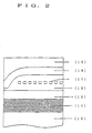
- FIG. 1 there is illustrated one preferred embodiment of the thin film type magnetic head used herein.
- the head shown in FIG. 1 includes a slider 1, an insulating underlay layer 2, and a lower shield layer 3 stacked in this order.
- An MR element 4 is formed on the lower shield layer 3 while it is buried in a gap insulating layer 5.
- An upper shield layer 6 is formed on the gap insulating layer 5.
- An MR head section for reproducing is constructed by the lower shield layer 3, MR element 4, gap insulating layer 5, and upper shield layer 6.
- An inductive head section for recording is constructed by these components.
- the slider 1 is formed of any desired one of conventional well-known materials, for example, ceramics and ferrite.
- ceramics especially ceramic materials based on Al 2 O 3 -TiC, ceramic materials based on ZrO 2 , ceramic materials based on SiC, and ceramic materials based on AlN. These ceramic materials may further contain Mg, Y, ZrO 2 , TiO 2 , etc. as additives.
- the slider 1 may have any desired shape, size and other parameters which are selected from known ones in accordance with a particular application.
- any of well-known materials is useful.
- SiO 2 , glass, Al 2 O 3 or the like may be used when it is desired to form such a thin film by sputtering.
- Ni-Fe system alloys as typified by Permalloy are preferred and they are deposited by sputtering or plating technique.
- the MR element 4 is formed by depositing the lower gap insulating layer 5 on the lower shield layer 3 by sputtering or the like and depositing an MR film by sputtering or the like, followed by patterning. Leads (not shown) of copper or similar conductor are connected to the MR element 4 as by plating. If necessary, a shunt layer and a soft film bias layer are formed by sputtering or the like for biasing the MR element 4.
- the MR element 4 is constructed of any of materials having large magnetoresistance effect, preferably Ni-Fe system alloys such as Permalloy.
- the gap insulating layer 5 is formed of SiO 2 , Al 2 O 3 or the like.
- any of conventional well-known materials may be used.
- Preferred are Ni-Fe system alloys such as Permalloy, which are deposited by sputtering, plating or the like.
- the insulating layer 7 any of conventional well-known materials is useful. For example, SiO 2 , glass, Al 2 O 3 or the like may be used when it is desired to form such a thin film by sputtering.
- the insulating layer 7 is as conventional with respect to thickness and pattern. For example, it is about 5 to 40 ⁇ m thick.
- the magnetic layer is provided as the lower and upper magnetic pole layers 8 and 11 as shown in the figure.
- the lower and upper magnetic pole layers 8 and 11 are soft magnetic thin films having a saturation magnetic flux density of at least 0.7 T.
- the soft magnetic material of which these magnetic pole layers are formed is not particularly limited. A preferred choice is made among Fe-Al-Si system alloys such as Sendust, Fe-Al-Si-Ni system alloys such as Super Sendust, Fe-Si system alloys, Ni-Fe system alloys such as Permalloy, and Fe-N system alloys. For each soft magnetic thin film, a structure of multiple strata of such Fe system alloys is acceptable.
- the lower and upper magnetic pole layers 8 and 11 may be either identical or different in composition. Further, the lower and upper magnetic pole layers 8 and 11 are as conventional with respect to their pattern and thickness. For example, the magnetic pole layer is about 1 to 5 ⁇ m thick.
- the gap layer 9 any of conventional well-known materials such as SiO 2 and Al 2 O 3 is useful.
- the gap layer 9 is as conventional with respect to its pattern and thickness. For example, it is about 0.2 to 1.0 ⁇ m thick.
- the coil layer 10 may be made any desired material, for example, commonly used metals such as Al and Cu. No limit is imposed on the winding pattern and density of the coil which may be selected from well-known ones. For example, the winding pattern is illustrated as spiral in the figure although laminate and zigzag patterns are also acceptable. For forming the coil layer 10, any of deposition techniques including sputtering, plating and evaporation may be used.
- the coil layer 10 is of conventional spiral pattern wherein it is spirally extended between the lower and upper magnetic pole layers 8 and 11 and insulated therefrom by the insulating layer 9.
- the protective layer 12 any of conventional well-known materials is useful.
- the protective layer 12 is as conventional with respect to its pattern and thickness. For example, it is about 10 to 50 ⁇ m thick.
- a coating of any desired resin may be disposed at the top of the illustrated structure.
- the thin film type magnetic head is manufactured by a process including thin film forming steps and patterning steps.
- any of conventional well-known gas phase deposition techniques for example, vacuum evaporation and sputtering may be used as well as plating.
- any of conventional well-known techniques for example, selective etching and selective deposition may be used. Etching can be either wet or dry etching.
- the thin film type magnetic head described above is used in assembly with an arm and other members.
- the head can be designed to provide any desired flying distance by adjusting the shape of the slider, the loads of gimbal and suspension, the number of revolutions of the magnetic disk, and the like.
- FIG. 5 is a block diagram of a read circuit following the read head which is operated in combination with a magnetic recording medium.
- the circuit includes the head, a head amplifier, a filter, a differentiator, a zero-cross comparator, a data synchronizer, and an output electrically connected in the described order.
- the differentiator is omitted from this circuit.
- Magnetic disks designated E, F, G, H, I, J, K, L, M, N, and P were prepared using different magnetic layers.
- Magnetic powder Magnetic disk Composition Coercivity (Oe) E Ba ferrite 700 F Ba ferrite 1000 G Ba ferrite 1300 H, I, J, K, L, M Ba ferrite 1750 N ⁇ -Fe 1800 P Co- ⁇ -Fe 2 O 3 770
- Magnetic paint Parts by weight Magnetic powder 100 ⁇ -Al 2 O 3 3
- Polyvinyl phenol resin Marukalinka® S2P, Maruzen Petroleum Chemical K.K.
- Epoxy resin Epoxy resin
- Phosphate ester Phospharol® 610E
- the components were mixed and dispersed in a ball mill for 140 hours to give a magnetic coating composition having a viscosity of 150 to 900 centipoise.
- the magnetic coating compositions were applied to either surface of disk-shaped aluminum substrates of 3.5 inch diameter by spin coating.
- the aluminum substrates had a surface roughness Rmax of 0.038 ⁇ m.
- the compositions were coated at 3,500 to 4,500 rpm at spinning off for 10 to 20 seconds so as to give coatings having an average thickness of 0.30 ⁇ m at the end of curing.
- the compositions were coated at 2,500 to 3,500 rpm at spinning off for 10 to 20 seconds so as to give coatings having an average thickness of 0.40 ⁇ m at the end of curing.
- the compositions were coated at 1,500 to 2,500 rpm at spinning off for 5 to 10 seconds so as to give coatings having an average thickness of 0.60 ⁇ m and 1.0 ⁇ m at the end of curing, respectively.
- each coated disk was rotated across a leveling device consisting of N-S opposed rod-shaped magnets at room temperature (23°C) for leveling the coating.
- the coated disks except for disk M were subject to orienting treatment in a disk circumferential direction through an orienting device consisting of opposed magnets and then the coatings were dried.
- the orienting magnetic field had an intensity of 1,000 G for disk L and 2,000 to 40,000 G for the remaining disks, as measured in the coatings, which corresponded twice or more the coercivity of the magnetic powder used.
- the disks were rotated at 200 rpm and the orienting time was 45 seconds.
- the coatings were cured by heating at 200°C for 3 hours in a nitrogen stream.
- the coatings were polished using a tape polishing machine with abrasive tape WA 6000 or WA 8000 (commercially available from Nippon Micro-Coating K.K.) for fine thickness adjustment and smoothing of the magnetic layer.
- the disks were cleaned and coated with a flon solution of fluorocarbon (Fomblin AM2001, Montecatini) at 0.1% concentration by dipping whereupon the coatings were impregnated with the fluorocarbon. In this way, the coated magnetic disks were completed.
- a flon solution of fluorocarbon Fomblin AM2001, Montecatini
- Thin film type magnetic disks Q, R, and S were prepared which had magnetic layers with different coercivity.
- a disk-shaped aluminum substrate of 3.5 inch diameter was formed with an Ni-P undercoat layer of 20 ⁇ m thick by electroless plating and surface smoothed by means of an abrasive polishing machine.
- a chromium layer of 0.2 ⁇ m thick was deposited by means of a magnetron sputtering device, and a magnetic layer of Co-Ni-Cr or Co-Ni-Ta alloy was then deposited to a thickness of 0.05 ⁇ m.
- the magnetic layer of Co-Ni-Ta alloy was changed in coercivity by adjusting the substrate heating condition and Ar gas pressure.
- a carbon protective film of 0.04 ⁇ m thick was deposited by RF magnetron sputtering.
- the flon solution of fluorocarbon was applied to the protective film to form a protective lubricating film. In this way, the thin film type magnetic disks were completed.
- a MR reproducing head section was prepared as shown in FIG. 1 by successively building up the insulating underlay layer 2, lower shield layer 3, MR element 4, gap insulating layer 5 and upper shield layer 6 on the slider 1.
- An inductive head section was formed on the MR reproducing head by successively building up the insulating layer 7, lower magnetic layer 8, gap insulating layer 9, coil conductor 10, upper magnetic layer 11, and protective layer 12 thereon. In this way, an inductive MR composite thin film head was manufactured.
- the respective layers were deposited by sputtering or plating and patterned by dry etching.
- the slider 1 used was of Al 2 O 3 -TiC.
- the insulating layer 2 was of Al 2 O 3 .
- the lower and upper shield layers 3 and 6 were Permalloy films having a saturation magnetic flux density of 0.8 T formed by a plating technique.
- the gap layer 5 was of Al 2 O 3 .
- the MR element 4 was formed by depositing Permalloy on a lower gap insulating layer by sputtering and patterning the deposit by dry etching, whereupon an upper gap insulating layer was deposited thereon to complete the gap insulating layer.
- the MR element 4 had a thickness of 0.35 ⁇ m which corresponded to a gap distance.
- the insulating layer 7 was a film of Al 2 O 3 having a thickness of 30 ⁇ m.
- the lower and upper magnetic layers 8 and 11 were films of Permalloy with a saturation magnetic flux density of 0.8 T which had a thickness of 1.7 ⁇ m and 2.0 ⁇ m, respectively. They were deposited by magnetron sputtering.
- the gap insulating layer 9 was of SiO 2 and had a gap distance of 0.35 ⁇ m.
- the coil layer 10 was formed by depositing copper in a spiral pattern.
- the protective film 12 was of Al 2 O 3 and had a thickness of 40 ⁇ m.
- a slider block was shaped as shown in FIG. 3 and assembled with a gimbal and an arm to complete a flying magnetic head, which is designated magnetic head A.
- An inductive thin film type magnetic head was prepared as shown in FIG. 2 by successively building up an insulating layer 14, lower magnetic layer 15, gap insulating layer 16, coil conductor 17, gap insulating layer 16, upper magnetic layer 18, and protective layer 19 on a slider 13.
- the respective layers were deposited by sputtering and patterned by dry etching.
- the slider 13 used was of Al 2 O 3 -TiC.
- the insulating layer 14 was of Al 2 O 3 and had a thickness of 30 ⁇ m.
- the lower and upper magnetic layers 15 and 18 were films of Permalloy with a saturation magnetic flux density of 0.8 T which had a thickness of 1.7 ⁇ m and 2.0 ⁇ m, respectively. They were deposited by magnetron sputtering.
- the gap insulating layer 16 was of SiO 2 and had a gap distance of 0.65 ⁇ m.
- the coil layer 17 was formed by depositing copper in a spiral pattern.
- the protective film 19 was of Al 2 O 3 and had a thickness of 40 ⁇ m.
- a slider block was shaped as shown in FIG. 3 and assembled with a gimbal and an arm to complete a flying magnetic head, which is designated magnetic head B.
- a Mn-Zn sintered ferrite block having a saturation magnetization of 0.36 T was machined to form a V-shaped groove.
- a Sendust film 22 having a saturation magnetic flux density of 1.1 T and a thickness of 2 ⁇ m was formed by magnetron sputtering. After appropriate machining, the ferrite cores are fusion welded with a low-melting glass 23 so as to define a gap 24.
- the gap was constructed of SiO 2 and had a distance of 0.3 ⁇ m. A magnetic head core was obtained.
- a copper coil was wound 24 turns on the magnetic head core to provide a MIG magnetic head.
- the head was assembled with a gimbal and an arm to complete a flying magnetic head, which is designated head C.
- a ferrite magnetic head was prepared by machining a Mn-Zn sintered ferrite block having a saturation magnetization of 0.36 T. This is designated head D.
- the magnetic layers of the magnetic disk samples were measured for average thickness (t) and surface roughness (Ra).
- the thickness (t) of the magnetic layer was determined by partially removing the magnetic layer from a disk sample on test and measuring the step between the magnetic layer surface and the magnetic layer-free area by means of a probe type surface roughness meter, Talistep.
- the surface roughness (Ra) was determined by the method prescribed in JIS B-0601.
- the magnetic layers were measured for coercivity (Hc), squareness ratio (S), and coercivity squareness ratio (S*) in the movement direction relative to the head using a vibrating sample magnetometer (VSM) under a maximum applied magnetic field of 10 kG.
- Hc coercivity
- S squareness ratio
- S* coercivity squareness ratio
- the magnetic heads were measured for saturation magnetic flux density (Bs) and inductance (I) in the proximity of the gap.
- the saturation magnetic flux density (Bs) was measured by means of a VSM after deposition of the magnetic film.
- the inductance (I) measurement used an impedance analyzer (manufactured by Hughlet Packard).
- Magnetic disk drives having the respective flying magnetic heads built therein were loaded with the respective magnetic disks and operated for recording and reproducing signals while the following tests were done.
- the combination of head and disk is shown in Table 1.
- the inductive MR composite thin film magnetic heads used had a recording gap distance of 0.7 ⁇ m and a reproducing gap distance of 0.3 ⁇ m.
- the head was kept afloat on the rotating disk at a flying distance of 0.13 ⁇ m.
- the flying distance is the distance between the magnetic head surface and the bearing surface of the magnetic head at the gap.
- the flying distance was measured by rotating a special quartz disk under the same conditions normally employed for other measurements, thereby pneumatically keeping the magnetic head afloat on the disk surface, directing white light to the gap of the head from the rear side of the quartz disk, detecting the interference between the light reflected by the head gap and the light reflected by the disk surface, and calculating the flying distance therefrom.
- a recording density D 70 was measured by varying the recording frequency. It was determined from the recording frequency at which the peak-to-peak (P-P) value of reproduction output decreased to 70% of the P-P value of solitary wave reproduction output.
- Modulation noise was evaluated in terms of a C/N ratio.
- the C/N ratio was determined by recording signals of 19 MHz, reproducing the signals, and determining the difference between reproduction output at 19 MHz and modulation noise at 6 MHz by means of a spectrum analyzer (manufactured by Hughlet Packard).
- Overwrite ability was measured by overwriting 2F signals (2.25 MHz) over 1F signals (9 MHz) and measuring the attenuation of the 1F signals by means of a spectrum analyzer (manufactured by Hughlet Packard).
- Bit shift (BS) was evaluated by recording the worst pattern (3E1E) at frequency 13.5 MHz in accordance with 1-7 modulation code and measuring the bit shift quantity (BS) at a sampling number of 10 9 by means of a time interval analyzer (manufactured by ITI).
- combination Nos. 1 to 3 falling within the scope of the invention offered a high linear recording density D 70 of 61 KFCI or more, a C/N ratio representing modulation noise of 48 dB or more, an overwrite ability (O/W) of -37 dB or better, and a bit shift (BS) of 12.6 ns or less.
- Combination Nos. 7 and 8 in which the magnetic layers had a squareness ratio (S) of lower than 0.7 were acceptable in linear recording density and overwrite ability, but were substantially deteriorated in bit shift probably because of distortion of reproduction waveform.
- Combination No. 9 in which the magnetic layer had a coercivity (Hc) of lower than 1,100 Oe was acceptable in overwrite ability, but was poor in linear recording density and modulation noise and substantially deteriorated in bit shift.
- Combination No. 10 using the magnetic disk having a coated magnetic layer containing ⁇ -Fe was poor in modulation noise and deteriorated in bit shift.
- Combination No. 11 using the magnetic disk having a coated magnetic layer containing Co- ⁇ -Fe 2 O 3 was poor in linear recording density and modulation noise and deteriorated in bit shift.
- Combination Nos. 12, 13 and 14 using the magnetic disks having the thin film type magnetic layers were acceptable in linear recording density and overwrite ability, but were poor in modulation noise and insufficient in bit shift.
- Combination Nos. 18, 19 and 20 using the MIG magnetic head were poor in linear recording density and modulation noise and deteriorated in bit shift.
- Combination No. 21 using the ferrite magnetic head was poor in linear recording density and modulation noise and deteriorated in overwrite ability and bit shift.
- Magnetic disks designated E', F', G', H', I', J', and K' were prepared using different magnetic layers.
- Magnetic powder Magnetic disk Composition Coercivity (Oe) E', F', G', H', I' Ba ferrite 1750 J' ⁇ -Fe 1800 K' Co- ⁇ -Fe 2 O 3 770
- Magnetic paint Parts by weight Magnetic powder 100 ⁇ -Al 2 O 3 3
- Polyvinyl phenol resin Marukalinka® S2P, Maruzen Petroleum Chemical K.K.
- Epoxy resin Epoxy resin
- Phosphate ester Phospharol® 610E
- the components were mixed and dispersed in a ball mill for 140 hours to give a magnetic coating composition having a viscosity of 150 to 900 centipoise.
- the magnetic coating compositions were applied to either surface of disk-shaped aluminum substrates of 3.5 inch diameter by spin coating.
- the aluminum substrates had a surface roughness Rmax of 0.038 ⁇ m.
- the compositions were coated at 3,500 to 4,500 rpm at spinning off for 10 to 20 seconds so as to give coatings having an average thickness of 0.30 ⁇ m at the end of curing.
- the composition was coated at 2,500 to 3,500 rpm at spinning off for 10 to 20 seconds so as to give a coating having an average thickness of 0.40 ⁇ m at the end of curing.
- each coated disk was rotated across a leveling device consisting of N-S opposed rod-shaped magnets at room temperature (23°C) for leveling the coating.
- the coated disks were subject to orienting treatment in a disk circumferential direction through an orienting device consisting of opposed magnets and then the coatings were dried.
- the orienting magnetic field magnets with opposite poles faced each other created a magnetic field of 1,000 to 7,000 G as measured in the coatings for disks E', F', and G'.
- Magnets with identical poles faced each other created a magnetic field of 500 to 4,000 G as measured in the coatings for disks H', I', J', and K'.
- the disks were rotated at 200 rpm and the orienting time was 45 seconds.
- the coatings were cured by heating at 200°C for 3 hours in a nitrogen stream.
- the coatings were polished using a tape polishing machine with abrasive tape WA 6000 or WA 8000 (commercially available from Nippon Micro-Coating K.K.) for fine thickness adjustment and smoothing of the magnetic layer.
- the disks were cleaned and coated with a flon solution of fluorocarbon (Fomblin AM2001, Montecatini) at 0.1% concentration by dipping whereupon the coatings were impregnated with the fluorocarbon. In this way, the coated magnetic disks were completed.
- a flon solution of fluorocarbon Fomblin AM2001, Montecatini
- the magnetic layers were measured for surface roughness (Ra) by the method prescribed in JIS B-0601 to find that they all had Ra of less than 5 nm.
- Thin film type magnetic disks L', M', and N' were prepared which had magnetic layers with different coercivity.
- a disk-shaped aluminum substrate of 3.5 inch diameter was formed with an Ni-P undercoat layer of 20 ⁇ m thick by electroless plating and surface smoothed by means of an abrasive polishing machine.
- a chromium layer of 0.2 ⁇ m thick was deposited by magnetron sputtering, and a magnetic layer of Co-Ni-Cr or Co-Ni-Ta alloy was then deposited to a thickness of 0.05 ⁇ m.
- the magnetic layer of Co-Ni-Ta alloy was changed in coercivity by adjusting the substrate heating condition and Ar gas pressure.
- a carbon protective film of 0.04 ⁇ m thick was deposited by RF magnetron sputtering.
- the flon solution of fluorocarbon was applied to the protective film to form a protective lubricating film. In this way, the thin film type magnetic disks were completed.
- a MR reproducing head section was prepared as shown in FIG. 1 by successively building up the insulating underlay layer 2, lower shield layer 3, MR element 4, gap insulating layer 5 and upper shield layer 6 on the slider 1.
- An inductive head section was formed on the MR reproducing head by successively building up the insulating layer 7, lower magnetic layer 8, gap insulating layer 9, coil conductor 10, upper magnetic layer 11, and protective layer 12 thereon. In this way, an inductive MR composite thin film head was manufactured.
- the respective layers were deposited by sputtering or plating and patterned by dry etching.
- the slider 1 used was of Al 2 O 3 -TiC.
- the insulating layer 2 was of Al 2 O 3 .
- the lower and upper shield layers 3 and 6 were Permalloy films having a saturation magnetic flux density of 0.8 T formed by a plating technique.
- the gap layer 5 was of Al 2 O 3 .
- the MR element 4 was formed by depositing Permalloy on a lower gap insulating layer by sputtering and patterning the deposit by dry etching, whereupon an upper gap insulating layer was deposited thereon to complete the gap insulating layer.
- the MR element 4 had a thickness of 0.35 ⁇ m which corresponded to a gap distance.
- the insulating layer 7 was a film of Al 2 O 3 having a thickness of 30 ⁇ m.
- the lower and upper magnetic layers 8 and 11 were films of Permalloy with a saturation magnetic flux density of 0.8 T which had a thickness of 1.7 ⁇ m and 2.0 ⁇ m, respectively. They were deposited by magnetron sputtering.
- the gap insulating layer 9 was of SiO 2 and had a gap distance of 0.35 ⁇ m.
- the coil layer 10 was formed by depositing copper in a spiral pattern.
- the protective film 12 was of Al 2 O 3 and had a thickness of 40 ⁇ m.
- a slider block was shaped as shown in FIG. 3 and assembled with a gimbal and an arm to complete a flying magnetic head, which is designated magnetic head A.
- An inductive thin film type magnetic head was prepared as shown in FIG. 2 by successively building up an insulating layer 14, lower magnetic layer 15, gap insulating layer 16, coil conductor 17, gap insulating layer 16, upper magnetic layer 18, and protective layer 19 on a slider 13.
- the respective layers were deposited by sputtering and patterned by dry etching.
- the slider 13 used was of Al 2 O 3 -TiC.
- the insulating layer 14 was of Al 2 O 3 and had a thickness of 30 ⁇ m.
- the lower and upper magnetic layers 15 and 18 were films of Permalloy with a saturation magnetic flux density of 0.8 T which had a thickness of 1.7 ⁇ m and 2.0 ⁇ m, respectively. They were deposited by magnetron sputtering.
- the gap insulating layer 16 was of SiO 2 and had a gap distance of 0.65 ⁇ m.
- the coil layer 17 was formed by depositing copper in a spiral pattern.
- the protective film 19 was of Al 2 O 3 and had a thickness of 40 ⁇ m.
- a slider block was shaped as shown in FIG. 3 and assembled with a gimbal and an arm to complete a flying magnetic head, which is designated magnetic head B.
- a Mn-Zn sintered ferrite block having a saturation magnetization of 0.36 T was machined to form a V-shaped groove.
- a Sendust film 22 having a saturation magnetic flux density of 1.1 T and a thickness of 2 ⁇ m was formed by magnetron sputtering. After appropriate machining, the ferrite cores are fusion welded with a low-melting glass 23 so as to define a gap 24.
- the gap was constructed of SiO 2 and had a distance of 0.3 ⁇ m. A magnetic head core was obtained.
- a copper coil was wound 24 turns on the magnetic head core to provide a MIG magnetic head.
- the head was assembled with a gimbal and an arm to complete a flying magnetic head, which is designated head C.
- a ferrite magnetic head was prepared by machining a Mn-Zn sintered ferrite block having a saturation magnetization of 0.36 T. This is designated head D.
- the magnetic layers of the magnetic disk samples were measured for average thickness (t).
- the thickness (t) of the magnetic layer was determined by partially removing the magnetic layer from a disk sample on test and measuring the step between the magnetic layer surface and the magnetic layer-free area by means of a probe type surface roughness meter, Talistep.
- the magnetic layers were measured for coercivity (Hc) in the direction of movement relative to the head, squareness ratio (S ⁇ ) and coercivity squareness ratio (S ⁇ *) in a direction perpendicular to the recording surface using a vibrating sample magnetometer (VSM) under a maximum applied magnetic field of 10 kG.
- VSM vibrating sample magnetometer
- the magnetic heads were measured for saturation magnetic flux density (Bs) and inductance (I) in the proximity of the gap.
- the saturation magnetic flux density (Bs) was measured by means of a VSM after deposition of the magnetic film.
- the inductance (I) measurement used an impedance analyzer (manufactured by Hughlet Packard).
- Magnetic disk drives having the respective flying magnetic heads built therein were loaded with the respective magnetic disks and operated for recording and reproducing signals while the following tests were done.
- the combination of head and disk is shown in Table 2.
- the inductive MR composite thin film magnetic heads used had a recording gap distance of 0.7 ⁇ m and a reproducing gap distance of 0.3 ⁇ m.
- the head was kept afloat on the rotating disk at a flying distance of 0.13 ⁇ m.
- the flying distance is the distance between the magnetic head surface and the bearing surface of the magnetic head at the gap.
- the flying distance was measured by rotating a special quartz disk under the same conditions normally employed for other measurements, thereby pneumatically keeping the magnetic head afloat on the disk surface, directing white light to the gap of the head from the rear side of the quartz disk, detecting the interference between the light reflected by the head gap and the light reflected by the disk surface, and calculating the flying distance therefrom.
- a recording density D 70 was measured by varying the recording frequency. It was determined from the recording frequency at which the peak-to-peak (P-P) value of reproduction output decreased to 70% of the P-P value of solitary wave reproduction output.
- Modulation noise was evaluated in terms of a C/N ratio.
- the C/N ratio was determined by recording signals of 19 MHz, reproducing the signals, and determining the difference between reproduction output at 19 MHz and modulation noise at 6 MHz by means of a spectrum analyzer (manufactured by Hughlet Packard).
- Overwrite ability was measured by overwriting 2F signals (2.25 MHz) over 1F signals (9 MHz) and measuring the attenuation of the 1F signals by means of a spectrum analyzer (manufactured by Hughlet Packard).
- Bit shift (BS) was evaluated by recording the worst pattern (3E1E) at frequency 13.5 MHz in accordance with 1-7 modulation code and measuring the bit shift quantity (BS) at a sampling number of 10 9 by means of a time interval analyzer (manufactured by ITI). In evaluating the coated media using barium ferrite magnetic particles, a differential circuit was omitted from the measurement system.
- combination Nos. 101 to 103 falling within the scope of the invention offered a high linear recording density D 70 of 77 KFCI or more, a C/N ratio representing modulation noise of 45 dB or more, an overwrite ability (O/W) of -41 dB or more negative, and a bit shift (BS) of 9.1 ns or less.
- Combination Nos. 106 and 107 using the magnetic disks having a coated magnetic layer containing ⁇ -Fe or Co- ⁇ -Fe 2 O 3 was poor in linear recording density and modulation noise. Although a conventional circuit was used in the evaluation of bit shift, the bit shift was unsatisfactory.
- Combination Nos. 108, 109 and 110 using the magnetic disks having a thin film type magnetic layer were poor in linear recording density. Although a conventional circuit was used in the evaluation of bit shift, the bit shift was unsatisfactory.
- Combination No. 111 using the thin film magnetic head were acceptable in linear recording density, but poor in modulation noise, overwrite and bit shift.
- Combination Nos. 112 and 113 using the MIG magnetic head and ferrite magnetic head were poor in linear recording density, modulation noise, overwrite and bit shift.
- the present invention provides a reliable magnetic recording/reproducing method capable of high-density recording at low cost.
Landscapes
- Engineering & Computer Science (AREA)
- Manufacturing & Machinery (AREA)
- Magnetic Record Carriers (AREA)
- Recording Or Reproducing By Magnetic Means (AREA)
Applications Claiming Priority (5)
| Application Number | Priority Date | Filing Date | Title |
|---|---|---|---|
| JP15297293A JPH06342515A (ja) | 1993-05-31 | 1993-05-31 | 磁気記録再生方法 |
| JP15297293 | 1993-05-31 | ||
| JP15297393A JP3288136B2 (ja) | 1993-05-31 | 1993-05-31 | 磁気記録再生方法 |
| JP15297393 | 1993-05-31 | ||
| EP94108399A EP0627729A3 (en) | 1993-05-31 | 1994-05-31 | Magnetic recording/reproducing method. |
Related Parent Applications (1)
| Application Number | Title | Priority Date | Filing Date |
|---|---|---|---|
| EP94108399A Division EP0627729A3 (en) | 1993-05-31 | 1994-05-31 | Magnetic recording/reproducing method. |
Publications (3)
| Publication Number | Publication Date |
|---|---|
| EP0940803A2 true EP0940803A2 (de) | 1999-09-08 |
| EP0940803A3 EP0940803A3 (de) | 2000-03-01 |
| EP0940803B1 EP0940803B1 (de) | 2002-11-27 |
Family
ID=26481730
Family Applications (2)
| Application Number | Title | Priority Date | Filing Date |
|---|---|---|---|
| EP99108469A Expired - Lifetime EP0940803B1 (de) | 1993-05-31 | 1994-05-31 | Magnetische Aufzeichnungs-/Wiedergabemethode |
| EP94108399A Withdrawn EP0627729A3 (en) | 1993-05-31 | 1994-05-31 | Magnetic recording/reproducing method. |
Family Applications After (1)
| Application Number | Title | Priority Date | Filing Date |
|---|---|---|---|
| EP94108399A Withdrawn EP0627729A3 (en) | 1993-05-31 | 1994-05-31 | Magnetic recording/reproducing method. |
Country Status (3)
| Country | Link |
|---|---|
| US (1) | US5530609A (de) |
| EP (2) | EP0940803B1 (de) |
| DE (1) | DE69431815D1 (de) |
Families Citing this family (20)
| Publication number | Priority date | Publication date | Assignee | Title |
|---|---|---|---|---|
| JP3765428B2 (ja) * | 1995-02-21 | 2006-04-12 | 富士写真フイルム株式会社 | 磁気記録システム |
| EP0736840A3 (de) * | 1995-04-07 | 2000-03-15 | Eastman Kodak Company | Magnetisch kodierbare Karte mit magnetischem Pigment gleichmässig verteilt in Plastik und Herstellungsverfahren |
| JPH0922512A (ja) * | 1995-07-05 | 1997-01-21 | Sony Corp | 複合型薄膜磁気ヘッド及びその製造方法 |
| JP3520170B2 (ja) * | 1996-04-02 | 2004-04-19 | Tdk株式会社 | 複合型薄膜磁気ヘッド |
| JP3420896B2 (ja) * | 1996-09-10 | 2003-06-30 | アルプス電気株式会社 | 薄膜磁気ヘッドおよびその製造方法 |
| JPH1083517A (ja) * | 1996-09-10 | 1998-03-31 | Alps Electric Co Ltd | 薄膜磁気ヘッド及びその製造方法 |
| JPH10188222A (ja) * | 1996-12-20 | 1998-07-21 | Read Rite S M I Kk | 複合型薄膜磁気ヘッド |
| JP2001229512A (ja) | 2000-02-10 | 2001-08-24 | Tdk Corp | 薄膜磁気ヘッドおよびその製造方法 |
| US6916521B2 (en) * | 2000-12-13 | 2005-07-12 | Fuji Photo Film Co., Ltd. | Cleaning medium for magnetic recording apparatus |
| US6836392B2 (en) * | 2001-04-24 | 2004-12-28 | Hitachi Global Storage Technologies Netherlands, B.V. | Stability-enhancing underlayer for exchange-coupled magnetic structures, magnetoresistive sensors, and magnetic disk drive systems |
| US20060011487A1 (en) * | 2001-05-31 | 2006-01-19 | Surfect Technologies, Inc. | Submicron and nano size particle encapsulation by electrochemical process and apparatus |
| WO2003018875A1 (en) * | 2001-08-27 | 2003-03-06 | Surfect Techologies, Inc. | Electrodeposition apparatus and method using magnetic assistance and rotary cathode for ferrous and magnetic particles |
| WO2004052547A2 (en) * | 2002-12-05 | 2004-06-24 | Surfect Technologies, Inc. | Coated and magnetic particles and applications thereof |
| US20050166218A1 (en) * | 2002-12-24 | 2005-07-28 | Fujitsu Limited | Magneto-optical recording medium and method for producing the same |
| JP2004334946A (ja) * | 2003-05-02 | 2004-11-25 | Fuji Photo Film Co Ltd | 磁気記録媒体 |
| WO2005076977A2 (en) * | 2004-02-04 | 2005-08-25 | Surfect Technologies, Inc. | Plating apparatus and method |
| JP5185200B2 (ja) * | 2009-06-02 | 2013-04-17 | 富士フイルム株式会社 | 六方晶フェライト磁性粉末およびその製造方法、ならびに磁気記録媒体およびその製造方法 |
| US8570683B2 (en) * | 2011-06-24 | 2013-10-29 | HGST Netherlands B.V. | Low permeability material for a side shield in a perpendicular magnetic head |
| US8630060B2 (en) * | 2012-03-09 | 2014-01-14 | HGST Netherlands B.V. | Thermally enabled exchange coupled media for magnetic data recording |
| US9558777B2 (en) | 2014-11-26 | 2017-01-31 | HGST Netherlands B.V. | Heat assisted magnetic recording (HAMR) media having a highly ordered crystalline structure |
Family Cites Families (12)
| Publication number | Priority date | Publication date | Assignee | Title |
|---|---|---|---|---|
| JPS6194230A (ja) * | 1984-10-16 | 1986-05-13 | Victor Co Of Japan Ltd | 磁気記録媒体 |
| JPH0640361B2 (ja) * | 1985-03-07 | 1994-05-25 | 日本ビクター株式会社 | 垂直磁気記録再生方法 |
| JPS6249656A (ja) * | 1985-08-29 | 1987-03-04 | Matsushita Electric Ind Co Ltd | ヘテロ接合バイポ−ラトランジスタおよびその製造方法 |
| JPS6250888A (ja) * | 1985-08-30 | 1987-03-05 | 株式会社東芝 | 表示システム |
| JPS6313242A (ja) * | 1986-07-04 | 1988-01-20 | Sony Corp | 陰極線管の内蔵抵抗器 |
| US4841398A (en) * | 1987-02-17 | 1989-06-20 | Magnetic Peripherals Inc. | Non linear magnetoresistive sensor |
| JPH01155502A (ja) * | 1987-12-14 | 1989-06-19 | Tdk Corp | 磁気記録再生装置 |
| JPH02168408A (ja) * | 1988-09-19 | 1990-06-28 | Hitachi Ltd | 記録再生用磁気ヘッドおよびその製造方法 |
| JPH03157801A (ja) * | 1989-11-16 | 1991-07-05 | Tdk Corp | 磁気記録再生方法 |
| US5182693A (en) * | 1989-12-29 | 1993-01-26 | Tdk Corporation | Magnetic disk |
| KR100242036B1 (ko) * | 1991-01-08 | 2000-02-01 | 다카노 야스아키 | 자기 헤드 |
| EP0576376B1 (de) * | 1992-06-26 | 1998-05-06 | Eastman Kodak Company | Kobalt-Platin magnetischer Film und Herstellungsverfahren |
-
1994
- 1994-05-31 EP EP99108469A patent/EP0940803B1/de not_active Expired - Lifetime
- 1994-05-31 DE DE69431815T patent/DE69431815D1/de not_active Expired - Lifetime
- 1994-05-31 EP EP94108399A patent/EP0627729A3/en not_active Withdrawn
- 1994-05-31 US US08/251,360 patent/US5530609A/en not_active Expired - Lifetime
Also Published As
| Publication number | Publication date |
|---|---|
| DE69431815D1 (de) | 2003-01-09 |
| EP0940803A3 (de) | 2000-03-01 |
| EP0627729A3 (en) | 1995-11-02 |
| EP0940803B1 (de) | 2002-11-27 |
| EP0627729A2 (de) | 1994-12-07 |
| US5530609A (en) | 1996-06-25 |
Similar Documents
| Publication | Publication Date | Title |
|---|---|---|
| EP0940803B1 (de) | Magnetische Aufzeichnungs-/Wiedergabemethode | |
| US4442159A (en) | Magnetic recording medium | |
| US4486496A (en) | Magnetic recording medium | |
| WO2018199105A1 (ja) | 磁気記録媒体 | |
| US5160761A (en) | Method for making a magnetic disk | |
| US5140486A (en) | Magnetic recording and reproduction | |
| US5182693A (en) | Magnetic disk | |
| US5792570A (en) | Magnetic recording medium | |
| EP0515147B1 (de) | Magnetisches Aufzeichnungsmedium | |
| JP3288136B2 (ja) | 磁気記録再生方法 | |
| US5393584A (en) | Magnetic disc | |
| JP2549163B2 (ja) | スレーブ用磁気記録媒体およびその製造方法 | |
| JPH06342515A (ja) | 磁気記録再生方法 | |
| JP3852198B2 (ja) | 磁気記録媒体 | |
| JP2561455B2 (ja) | 磁気記録再生装置 | |
| US5443879A (en) | Longitudinal magnetic recording medium exhibiting various coercivitiy relationships | |
| Terada et al. | Signal-to-noise ratio studies on γ-Fe 2 O 3 thin film recording disks | |
| JPH0349025A (ja) | 磁気記録媒体 | |
| JPH03224124A (ja) | 磁気ディスク、磁気ディスクの製造方法および磁気記録再生方法 | |
| JP2821280B2 (ja) | 磁気記録媒体 | |
| JP3111841B2 (ja) | 磁気記録媒体 | |
| JP3012190B2 (ja) | 磁気記録媒体 | |
| JPH04113517A (ja) | 磁気ディスクの製造方法および磁気ディスク | |
| JPH06150296A (ja) | 磁気記録媒体 | |
| JPS6173206A (ja) | 磁気記録再生方式 |
Legal Events
| Date | Code | Title | Description |
|---|---|---|---|
| PUAI | Public reference made under article 153(3) epc to a published international application that has entered the european phase |
Free format text: ORIGINAL CODE: 0009012 |
|
| AC | Divisional application: reference to earlier application |
Ref document number: 627729 Country of ref document: EP |
|
| AK | Designated contracting states |
Kind code of ref document: A2 Designated state(s): DE FR GB NL |
|
| PUAL | Search report despatched |
Free format text: ORIGINAL CODE: 0009013 |
|
| AK | Designated contracting states |
Kind code of ref document: A3 Designated state(s): DE FR GB NL |
|
| 17P | Request for examination filed |
Effective date: 20000706 |
|
| GRAG | Despatch of communication of intention to grant |
Free format text: ORIGINAL CODE: EPIDOS AGRA |
|
| 17Q | First examination report despatched |
Effective date: 20020308 |
|
| GRAG | Despatch of communication of intention to grant |
Free format text: ORIGINAL CODE: EPIDOS AGRA |
|
| GRAH | Despatch of communication of intention to grant a patent |
Free format text: ORIGINAL CODE: EPIDOS IGRA |
|
| GRAH | Despatch of communication of intention to grant a patent |
Free format text: ORIGINAL CODE: EPIDOS IGRA |
|
| GRAA | (expected) grant |
Free format text: ORIGINAL CODE: 0009210 |
|
| AC | Divisional application: reference to earlier application |
Ref document number: 627729 Country of ref document: EP |
|
| AK | Designated contracting states |
Kind code of ref document: B1 Designated state(s): DE FR GB NL |
|
| PG25 | Lapsed in a contracting state [announced via postgrant information from national office to epo] |
Ref country code: NL Free format text: LAPSE BECAUSE OF FAILURE TO SUBMIT A TRANSLATION OF THE DESCRIPTION OR TO PAY THE FEE WITHIN THE PRESCRIBED TIME-LIMIT Effective date: 20021127 Ref country code: FR Free format text: LAPSE BECAUSE OF FAILURE TO SUBMIT A TRANSLATION OF THE DESCRIPTION OR TO PAY THE FEE WITHIN THE PRESCRIBED TIME-LIMIT Effective date: 20021127 |
|
| REG | Reference to a national code |
Ref country code: GB Ref legal event code: FG4D |
|
| REF | Corresponds to: |
Ref document number: 69431815 Country of ref document: DE Date of ref document: 20030109 |
|
| PG25 | Lapsed in a contracting state [announced via postgrant information from national office to epo] |
Ref country code: DE Free format text: LAPSE BECAUSE OF FAILURE TO SUBMIT A TRANSLATION OF THE DESCRIPTION OR TO PAY THE FEE WITHIN THE PRESCRIBED TIME-LIMIT Effective date: 20030228 |
|
| NLV1 | Nl: lapsed or annulled due to failure to fulfill the requirements of art. 29p and 29m of the patents act | ||
| EN | Fr: translation not filed | ||
| PLBE | No opposition filed within time limit |
Free format text: ORIGINAL CODE: 0009261 |
|
| STAA | Information on the status of an ep patent application or granted ep patent |
Free format text: STATUS: NO OPPOSITION FILED WITHIN TIME LIMIT |
|
| 26N | No opposition filed |
Effective date: 20030828 |
|
| PGFP | Annual fee paid to national office [announced via postgrant information from national office to epo] |
Ref country code: GB Payment date: 20090527 Year of fee payment: 16 |
|
| GBPC | Gb: european patent ceased through non-payment of renewal fee |
Effective date: 20100531 |
|
| PG25 | Lapsed in a contracting state [announced via postgrant information from national office to epo] |
Ref country code: GB Free format text: LAPSE BECAUSE OF NON-PAYMENT OF DUE FEES Effective date: 20100531 |