EP0942122A2 - Dispositif de verrouillage - Google Patents
Dispositif de verrouillage Download PDFInfo
- Publication number
- EP0942122A2 EP0942122A2 EP99104019A EP99104019A EP0942122A2 EP 0942122 A2 EP0942122 A2 EP 0942122A2 EP 99104019 A EP99104019 A EP 99104019A EP 99104019 A EP99104019 A EP 99104019A EP 0942122 A2 EP0942122 A2 EP 0942122A2
- Authority
- EP
- European Patent Office
- Prior art keywords
- bolt
- abutment
- locking device
- door
- locking
- Prior art date
- Legal status (The legal status is an assumption and is not a legal conclusion. Google has not performed a legal analysis and makes no representation as to the accuracy of the status listed.)
- Withdrawn
Links
- 230000033001 locomotion Effects 0.000 claims abstract description 50
- 230000008859 change Effects 0.000 claims description 16
- 230000005540 biological transmission Effects 0.000 claims description 7
- 230000003111 delayed effect Effects 0.000 claims description 6
- 230000006835 compression Effects 0.000 description 7
- 238000007906 compression Methods 0.000 description 7
- 230000000694 effects Effects 0.000 description 7
- 230000007246 mechanism Effects 0.000 description 5
- 230000008878 coupling Effects 0.000 description 3
- 238000010168 coupling process Methods 0.000 description 3
- 238000005859 coupling reaction Methods 0.000 description 3
- 238000013461 design Methods 0.000 description 3
- 238000006073 displacement reaction Methods 0.000 description 3
- 238000000034 method Methods 0.000 description 3
- 230000008569 process Effects 0.000 description 3
- 238000010276 construction Methods 0.000 description 2
- 102000004315 Forkhead Transcription Factors Human genes 0.000 description 1
- 108090000852 Forkhead Transcription Factors Proteins 0.000 description 1
- 241001417534 Lutjanidae Species 0.000 description 1
- 241000190070 Sarracenia purpurea Species 0.000 description 1
- 230000009471 action Effects 0.000 description 1
- 230000007613 environmental effect Effects 0.000 description 1
- 210000003746 feather Anatomy 0.000 description 1
- 239000002184 metal Substances 0.000 description 1
- 230000004048 modification Effects 0.000 description 1
- 238000012986 modification Methods 0.000 description 1
- 238000012545 processing Methods 0.000 description 1
- 238000012549 training Methods 0.000 description 1
- 238000012546 transfer Methods 0.000 description 1
Images


Classifications
-
- E—FIXED CONSTRUCTIONS
- E05—LOCKS; KEYS; WINDOW OR DOOR FITTINGS; SAFES
- E05B—LOCKS; ACCESSORIES THEREFOR; HANDCUFFS
- E05B63/00—Locks or fastenings with special structural characteristics
- E05B63/12—Locks or fastenings with special structural characteristics with means carried by the bolt for interlocking with the keeper
- E05B63/127—Locks or fastenings with special structural characteristics with means carried by the bolt for interlocking with the keeper the bolt having an additional rotating bolt or movement
-
- E—FIXED CONSTRUCTIONS
- E05—LOCKS; KEYS; WINDOW OR DOOR FITTINGS; SAFES
- E05B—LOCKS; ACCESSORIES THEREFOR; HANDCUFFS
- E05B15/00—Other details of locks; Parts for engagement by bolts of fastening devices
- E05B15/0006—Devices for aligning wing and frame; Anti-rattling devices
-
- E—FIXED CONSTRUCTIONS
- E05—LOCKS; KEYS; WINDOW OR DOOR FITTINGS; SAFES
- E05B—LOCKS; ACCESSORIES THEREFOR; HANDCUFFS
- E05B15/00—Other details of locks; Parts for engagement by bolts of fastening devices
- E05B15/10—Bolts of locks or night latches
- E05B15/102—Bolts having movable elements
-
- E—FIXED CONSTRUCTIONS
- E05—LOCKS; KEYS; WINDOW OR DOOR FITTINGS; SAFES
- E05B—LOCKS; ACCESSORIES THEREFOR; HANDCUFFS
- E05B17/00—Accessories in connection with locks
- E05B17/0025—Devices for forcing the wing firmly against its seat or to initiate the opening of the wing
-
- E—FIXED CONSTRUCTIONS
- E05—LOCKS; KEYS; WINDOW OR DOOR FITTINGS; SAFES
- E05B—LOCKS; ACCESSORIES THEREFOR; HANDCUFFS
- E05B15/00—Other details of locks; Parts for engagement by bolts of fastening devices
- E05B15/04—Spring arrangements in locks
- E05B2015/0431—Modifying spring characteristic or tension
Definitions
- the invention relates to a locking device consisting of a door lock and a striking plate assigned to it, the door lock one by actuating an actuating element has extendable latch, which in a first Position is retracted into the door lock so that the door is openable and in a second, extended position Strikes behind in the opening direction of the door, so that the door is locked.
- the bolt of the door lock can be a locking bolt represent, but in particular a door catch, as he usually does with house or apartment doors in addition to the locking bolt is present.
- the latch can thereby by a linear displacement or a swiveling movement extend parallel to the level of the door leaf.
- Doors or flaps have the problem that these are particularly with changing weather conditions with Warp moisture and temperature fluctuations, so that proper closing of the door is no longer possible.
- the door is then either only with increased effort to close, because for example the catch is no longer without further reaches behind the striking plate, or the door wobbles due to a game between the snap and the striking plate.
- the invention has for its object a locking device to create that always and also with changing Closes environmental conditions precisely and exactly, without a elaborate processing of the striking plate is necessary.
- This object is achieved in that at least a portion of the bolt motion-coupled to its extension movement parallel to the opening direction of the door is changeable, and in its end position parallel to Opening direction of the door is mounted so that it absorbs force the play between when the door is closed Bolt and striking plate is adjustable.
- the change in position of the bolt or bolt part transverse to the direction of extension can in particular by pivoting or Displacement take place, the pivot axis for example parallel to the bolt extension direction or perpendicular to this can stand.
- An adjustable abutment is advantageous for the area of the transom that changes in position transversely to the extension direction is provided, by means of which the end position of the variable Bolt area in relation to the striking plate is adjustable.
- the position of the bolt or parallel to the opening direction the partial position of the door is advantageous infinitely adjustable by adjusting the abutment.
- the spacing of the bolt from the is advantageous Strike plate when retracting the bolt both by actuation the handle and a key provided feasible.
- the handle of the door can be used as a handle or be carried out in another suitable form. But there are also includes locking devices in which the bolt through an actuator such as manually extended using a rotary knob without a snap mechanism is provided.
- the bolt can also be made in two or more parts and a first transverse to the direction of extension, that is parallel to Opening direction, fixed area and a second cross change in position to the exit direction, e.g. swiveling and / or displaceable, area.
- the first section the bolt can be used as a guide when the bolt is extended and retracted serve for the second section, in particular the the first partial area can be U-shaped, the second Part of the bolt arranged in the slot of the U-profile is.
- the partial areas of the transom which are mutually variable in position can be retractable and extendable at the same time.
- the coupling of movements can for example by a pen or driver respectively.
- an adjustable device For setting the end position of the cross to the direction of extension an adjustable device can be an adjustable device be provided with an actuator that on an abutment movable relative to the bolt acts, so that the position of the abutment by actuating the actuator is changeable, the end position by the abutment e.g. e.g. the maximum pivoting and / or shifting position the bolt can be changed when moving it in and out is.
- the movement of the latch across its inward and outward movement is thus coupled with this.
- the abutment can represent part of the bracket of the bolt, it can also run separately from the bracket as a separate warehouse be.
- a spring element is advantageously provided so that the transversely movable bolt or bolt area under spring force abuts the abutment.
- the latch can be a non-linear, e.g. bow or have an angular area that when extending or retracting the bolt can be guided over the abutment. It can also the pressure point of the abutment on the pivotable Area of the bolt to be arranged so that it is outside the travel plane of the axis of rotation of the pivotable area of the Riegel lies in the extending or retracting movement.
- the abutment can be rotated to reduce friction be executed, e.g. as a rotatably mounted bolt or rotatable stored ball.
- the abutment on a pivoted and / or slidably mounted Bracket can be arranged which is a substantially parallel Movement of the abutment relative to the bolt allows.
- the actuator of the adjusting device is advantageously from an area of the door lock that is accessible from the outside actuatable. This is a simple adjustment of the maximum Swivel position of the bolt in its extended position possible so that the locking device in a simple manner is adaptable to changing conditions.
- the actuator can for example from the lock shield, from which the bolt can be extended is actuatable or, for example, from the area of Base plates of the castle, which on the side of the lock shield adjoin.
- the actuator can also on or under a cover plate that may be provided.
- the setting device can also be a transmission element have, which acts on the abutment and for example is designed as a rod, the one made of sheet metal Components includes.
- the transmission element can another one for the abutment, for example in Form a recess for a bearing ball.
- the transmission element can have corresponding guides or be stored accordingly, according to a special design simple embodiment is the transmission element pivotally mounted on a part that has a relative movement to the bolt, or slidable along a guide.
- a linkage element loosely on a stationary Part of the locking device, e.g. the one on a side Base plate of the same, be stored.
- the setting device can be an eccentric and / or have a spindle drive, by means of which the end position the transversely variable locking part adjustable is.
- the locking device has a delay device by means of which the change in position such as a pivoting and / or shifting the one that can move across and out of the direction of travel Bolt or bolt part with a time delay to the Extending movement is executable.
- the closing process takes place thus two stages, so that when the bolt is already extended, this towards the striking plate e.g. pivoted and / or is shifted, whereby a particularly precise closing of the Door is possible.
- the latch can also be used be pressed against the striking plate with a certain force, which, for example, makes a fire door particularly tight can be. When opening the door can then be reversed First order the bolt from the striking plate spaced and then the bolt inserted become.
- the delay device can be designed that the change in position of the transversely movable bolt or Bolt part in the extension direction at a lower speed takes place as in the direction of entry.
- the closing process of the door is therefore comparatively slow, with the spacing the bolt from the striking plate takes place quickly when the door is opened, so that the door can be opened quickly.
- Means can also be provided by means of which the change in position of the transversely movable bolt part delayed to the extension movement of the one that is immobile in the transverse direction Bolt part can be done.
- the time delay may increase both on the extending movements of transverse and immovable bolt part relate to the fact that the Transverse movement of the transversely movable bolt part not with the Extension movement of the transversely immovable bolt part begins but delayed.
- this can be either indirect or direct couple to the transversely movable bolt part and on the other hand during the extension movement of the locking part relative to this movable component of the locking device, especially on a stationary part of the same as the lock base or a side wall.
- the locking device has a changeable abutment under which Change in position relative to the bolt transversely to the direction of extension is changeable, a first means for Transfer of the abutment at a first speed is provided in a first position, in which the Bolt in its initial position with respect to the transverse movement is located, and wherein a second means for transferring the Abutment at a second speed into a second Position relative to the bolt is provided, in which the latch in its end position with respect to the transverse movement is located, the second speed is less than that first.
- the bar or part of it can slow speed be moved in the transverse direction to the extension direction, wherein the abutment with a first, preferably significantly higher Speed can be converted to a starting position initiate the transverse movement of the bolt.
- the first means is preferably for moving the abutment coupled in this way to the actuating element of the locking device, that the abutment approximately simultaneously with the Extending the latch is transferred to its first position. The abutment is thus in its first position, when the latch is fully extended.
- the first and second means of transferring the abutment can have spring elements which when the Actuator simultaneously and in opposite to each other are exciting, i.e. claimed as a compression and tension spring become.
- the second spring element can cause a delayed pivoting movement of the bolt to enable an asymmetrical characteristic have, that is tension and relaxation of the spring element take place with different time constants.
- the spring elements of the delay device can be coupled be tensioned with the actuation of the actuating element.
- a linkage or a can be used as a holder for the abutment plate component such as an angle plate may be provided, wherein the delay device at one end of the linkage couples and the setting device for setting the maximum movement of the bolt transversely to its extension direction at the other end of the boom.
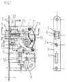
- a door lock is a locking device shown, which is typical for house or apartment doors is used.
- the striking plate assigned to the door lock (not shown) is such a conventional design.
- the door lock has a lock base plate 1 and a lock cover 2 (Figure 2) on the Serve the various facilities. Right Angle a lock shield 3 is provided for the lock base plate 1, so that the door lock can be mounted on the door leaf.
- the lock shield 2 has a passage opening 4 as a guide for a locking bar 5, which by means of a Breakthrough 6 arranged lock cylinder is actuated.
- a snap is passed through the lock plate 3, one across the direction of passage through the lock shield immovable part 7.
- the catch also points a partial area 8 which is transverse to the direction of passage through the lock plate 3, that is, transversely to the direction of entry and exit the catch is pivotable.
- the one from the lock sign 3 have outwardly projecting snap parts 7, 8 when the catch part 8 is not pivoted together in essentially the wedge-shaped contour of a conventional one Schnäppers on and are essentially the same distance from the lock shield 3.
- the non-swiveling catch part 7 is essentially U-shaped, wherein the swiveling catch part in the slot of the U-profile 8 is arranged.
- the catch parts 7, 8 are by means of of the cylindrical pin 9, which is also the pivot axis of the Snap part 8 forms, connected, so that the snap parts 7, 8 always moved into or out of the door lock become.
- the catch in its basic position the means when the door lock actuator is not actuated, is extended, both by a in the recess of the Snap return lever 10 used handle as well by actuating one inserted into the opening 6 Locking cylinder can be retracted.
- the return lever 10 acts directly onto the non-swiveling catch part 7, the torsion spring 11 being tensioned when the catch is retracted is so that when you release the handle of the catch returns to its extended basic position.
- Corresponding the catch can be activated by actuating the locking cylinder about displacement of the auxiliary lever 12 and pivoting the return lever 13 under tension of the torsion spring 11 can be retracted.
- the pivoting movement of the catch part 8 in the direction of the striking plate is supported by an abutment in the form of a ball 14 limited.
- the catch part 8 is on its inside the Door lock arranged area formed as an angle lever, wherein the ball 14 is arranged at the angle 16 and the long legs of the angle due to the leaf spring 15 below Exercise of torque always rests on the ball 14. Of the Point of contact of the long leg of the catch part 8 on the Ball 14 is spaced from the plane of movement of the cylindrical pin 9. This will result in a relative movement of the catch part 8 to the ball 14 when retracting or extending the Schnäppers this pivoted transversely to the direction of travel.
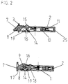
- an adjustment device with an adjustment plate 19 provided which has a recess for receiving the Ball 14 has, and thus at the same time as a holder for the abutment serves.
- the adjusting plate 19 is with his middle, outwardly projecting area 20 loosely in a Recess 21 of the lock base plate 1 inserted and thereby held in the door lock ( Figure 3).
- free end of the adjusting plate 9 engages an eccentric 22nd on in the bearing block attached to the lock base 1 23 is performed.
- the free one opposite the eccentric The end of the adjusting plate 19 engages behind the lock base plate 1, so that when pressure is applied to the catch part 8 on the ball 14 the forces transmitted to the adjusting plate 19 from the Bearing block 23 and the upper end of the adjusting plate 19th opposite area of the lock base plate 1 added become.
- the eccentric 22 can be rotated via the adjusting screw 24 protrudes from the lock plate 3 with its screw head and is therefore easily accessible from the outside.
- the catch in the fully extended condition shows is by turning the screw 24 and Eccentric 22 on the lower part of the adjusting plate 19th acts, this can be pivoted perpendicular to the lock base plate 1.
- the adjusting plate 19 is floating, it is however, more precise storage is also possible.
- Figure 3 shows the door lock in three different settings the maximum swiveling of the transversely movable Snap part 8.
- Figure 3 above, is the different position of the eccentric 22 and the adjusting plate 19, from Figure 3, below, the top view pointing to the lock shield 3, the resulting goes Pivot position of the catch part 8 out.
- the ball 14 is thereby by the spring pressure of the leaf spring 15 held in the recess of the adjusting plate 19.
- pivot point of the adjusting plate 19 is the top of the lock base 1 adjacent end.
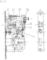
- FIGS Locking device shown, in which an additional delay device 44 is provided, by means of which the cross movable catch part 8 delayed to the extension movement of the catch in the direction of the striking plate becomes. Otherwise, the door locks of the two Embodiments identical in construction.
- the door lock according to FIG. 4 has an adjusting device Setting the maximum pivoting position of the pivotable Snap part 8 on that with a pivotable Adjustment plate 19 is provided, which around the rotatable adjusting bolt 26 is pivotable.
- the adjusting plate 19 again has in its central area a recess for mounting the ball 14, which acts as an abutment for the catch part 8 serves.
- the adjustment plate 19 with a projecting area 20 in the recess 21 of the lock base plate 1 used.
- the Adjusting bolt 26 opposite end of the adjusting plate 19th attacks a pivoting mechanism in order to move in or out of the catch the adjusting plate 19 coupled go away.
- the pivoting mechanism has a first cylinder spring 27, which is loaded as a tension spring and with a End at the end of the adjusting plate 19 and the other Attacks the end of a brake cylinder 28.
- the brake cylinder 28 has on its end facing the adjusting plate 19 a displaceable piston rod 29 on the fork head 30 pivotable on the adjusting plate by means of the hinge pin 31 is articulated.
- the articulation point is below the point of application the tension spring 27 arranged.
- the hinge pin 31 is on both sides in, if necessary slightly curved, elongated holes 32 out, each in the lock base plate 1 and the lock cover 2 are molded.
- the tension spring 27 opposite end of the brake cylinder 28 is with a provided relative to this immovable guide pin 33, at its free end from the wall of the door lock emerges and is provided with a stop 34.
- the assigned The end of the brake cylinder 28 has a spring 35 provided that is pressure-resistant.
- a driver 36 arranged by the Return lever 10 can be actuated so that the brake cylinder 28th is spacable from the adjusting plate 19.
- the brake cylinder 28 has an asymmetrical characteristic, that is, depending on the relative movement to the Piston rod 29 a different braking effect. Construction and Operation of the brake cylinder 28 can be seen in FIGS. 6, 8, 10 and 11, which show the brake cylinder in the present Phase of the opening or closing movement of the catch demonstrate.
- Piston rod 29 is rigidly attached to a piston 37, the one with a throttle bore 38 and with several passage openings 39 is provided.
- On the free end Side of the piston 37 is one through the spring 40 pressurized valve plate 41 arranged, which also has a plurality of passage openings 42, one of which the same always arranged in alignment with the throttle bore 38 and the others are offset to the passage openings 39 of the piston 37.
- Figure 7 shows the door lock with the return lever 13 in the stop when the catch is retracted. In this state, the Door to be closed. If the handle is then released, so the return lever 13 pivots due to the spring force the leaf spring 25 in its starting position and the Snap is extended with relaxation of the torsion spring 11.
- the Pivoting the catch part 8 thus only when complete extended snapper and not simultaneously with it Extension movement.
- the time delay of the pivoting of the Snap part 8 with respect to the extension of the bolt can can also be set to intermediate values so that the swivel movement starts before the catch is fully extended is.
- the time delay is particularly due to the characteristic of the brake cylinder 28 influenced, but also by the Training of the contact surfaces of the catch and abutment and the length of the travel of the abutment relative to swiveling catch part 8.
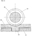
- Figures 14 to 16 show a modification of a locking device of Figures 1 to 4, but also in this embodiment appropriate delay devices are provided could be.
- the setting device a spindle drive that can be operated from the lock shield 3 is.
- the spindle 45 is rotatable in at its respective ends a bearing bush 46 and a bearing block 47.
- the one end of the spindle is accessible from the lock shield and provided with a rotary handle 48 so that it can be used as an adjusting screw works.
- On the spindle axis is a sleeve 49 with a thread secured against rotation, on the short leg of a Angle plate 50 attacks, which has a corresponding thread having.
- the angle plate 50 is on an axial guide 51 slidably supported, for which the short leg one along the extension direction of the transom or parallel to the main level of the locking device extending guide web 52 has, which engages in a longitudinal groove of the axial guide.
- the guide is on one or both of the closed base plates attached to the locking device. Through the closed Base plate, the locking device is versatile, as foreign objects enter the locking mechanism and the slide guide of the adjusting device, however is encapsulated by other means, is difficult.
- the long leg of the angle plate 50 is with a receptacle provided for the abutment ball 14 on the pivotable Snap part 8 rests under the force of a force, which is why non-pivoting catch part attached leaf spring 15 serves.
- a return spring 53 for the catch 7.8 provided the completely in a recess 54 of the Transversely movable catch part 7 is arranged and in extended state of the catch is relaxed.
- the recess 54 is slit-shaped towards the long side of the catch opened, with an abutment for the spring in the slot engages, which here as a notched web from the base plate 55 is formed.
Landscapes
- Engineering & Computer Science (AREA)
- Structural Engineering (AREA)
- Closing And Opening Devices For Wings, And Checks For Wings (AREA)
- Lock And Its Accessories (AREA)
Applications Claiming Priority (2)
| Application Number | Priority Date | Filing Date | Title |
|---|---|---|---|
| DE1998110700 DE19810700C2 (de) | 1998-03-12 | 1998-03-12 | Schließeinrichtung |
| DE19810700 | 1998-03-12 |
Publications (2)
| Publication Number | Publication Date |
|---|---|
| EP0942122A2 true EP0942122A2 (fr) | 1999-09-15 |
| EP0942122A3 EP0942122A3 (fr) | 2001-08-08 |
Family
ID=7860611
Family Applications (1)
| Application Number | Title | Priority Date | Filing Date |
|---|---|---|---|
| EP99104019A Withdrawn EP0942122A3 (fr) | 1998-03-12 | 1999-03-12 | Dispositif de verrouillage |
Country Status (2)
| Country | Link |
|---|---|
| EP (1) | EP0942122A3 (fr) |
| DE (2) | DE19810700C2 (fr) |
Cited By (3)
| Publication number | Priority date | Publication date | Assignee | Title |
|---|---|---|---|---|
| CN109057563A (zh) * | 2018-10-18 | 2018-12-21 | 张卫 | 多扣式对接锁 |
| CN116335492A (zh) * | 2023-03-22 | 2023-06-27 | 宁波韦迩五金工贸有限公司 | 一种自适应安装式锁具 |
| IT202300021609A1 (it) * | 2023-10-17 | 2025-04-17 | Stefano Ficco | Meccanismo di scrocco di una serratura |
Families Citing this family (1)
| Publication number | Priority date | Publication date | Assignee | Title |
|---|---|---|---|---|
| JP7137284B2 (ja) * | 2018-03-05 | 2022-09-14 | 技研金物株式会社 | 室内用ラッチ錠 |
Family Cites Families (8)
| Publication number | Priority date | Publication date | Assignee | Title |
|---|---|---|---|---|
| DE7222390U (de) * | 1972-09-14 | Groke Kg | Schließblech für Türschlösser | |
| DE341584C (de) * | 1915-03-26 | 1921-10-04 | Leon Ottinger | Tuerschloss |
| US2917336A (en) * | 1957-04-08 | 1959-12-15 | Schlage Lock Co | Anti-rattle latchbolt |
| DE1900212A1 (de) * | 1969-01-03 | 1970-07-30 | Werner Straehle | Tuerschloss |
| DE2215305A1 (de) * | 1972-03-29 | 1973-10-18 | August Buergers | Schliessblech fuer tueren |
| DE3821988A1 (de) * | 1988-06-30 | 1990-01-11 | Werner Straehle | Tuerschloss |
| DE19620043A1 (de) * | 1996-02-29 | 1997-09-04 | Karl Heger | Einsteckschloß |
| DE19639253C2 (de) * | 1996-05-23 | 1998-09-24 | Karl Heger | Schließblech |
-
1998
- 1998-03-12 DE DE1998110700 patent/DE19810700C2/de not_active Expired - Fee Related
-
1999
- 1999-03-12 EP EP99104019A patent/EP0942122A3/fr not_active Withdrawn
- 1999-03-12 DE DE29904647U patent/DE29904647U1/de not_active Expired - Lifetime
Non-Patent Citations (1)
| Title |
|---|
| None |
Cited By (4)
| Publication number | Priority date | Publication date | Assignee | Title |
|---|---|---|---|---|
| CN109057563A (zh) * | 2018-10-18 | 2018-12-21 | 张卫 | 多扣式对接锁 |
| CN109057563B (zh) * | 2018-10-18 | 2023-12-19 | 张卫 | 多扣式对接锁 |
| CN116335492A (zh) * | 2023-03-22 | 2023-06-27 | 宁波韦迩五金工贸有限公司 | 一种自适应安装式锁具 |
| IT202300021609A1 (it) * | 2023-10-17 | 2025-04-17 | Stefano Ficco | Meccanismo di scrocco di una serratura |
Also Published As
| Publication number | Publication date |
|---|---|
| DE29904647U1 (de) | 1999-07-29 |
| DE19810700A1 (de) | 1999-09-30 |
| DE19810700C2 (de) | 2000-04-13 |
| EP0942122A3 (fr) | 2001-08-08 |
Similar Documents
| Publication | Publication Date | Title |
|---|---|---|
| DE3605826C2 (fr) | ||
| DE2920581C2 (de) | Zusatzverriegelung, insbesondere Mittelverriegelung, für Fenster, Türen od.dgl. | |
| DE202008003694U1 (de) | Band zur schwenkbaren Befestigung eines Flügels, einer Tür, eines Fensters o.dgl. an einem feststehenden Rahmen | |
| EP3004504B1 (fr) | Ferme-porte pour un vantail de porte ou de fenetre | |
| EP2050908A1 (fr) | Mécanisme integré | |
| EP2206858A1 (fr) | Verrou de porte | |
| EP1384420B1 (fr) | Mécanisme de fermeture automatique amorti | |
| DE602004010217T2 (de) | Verriegelungsvorrichtung mit einem Gelenkhebel zum Spannen von Werkstücken | |
| EP0942122A2 (fr) | Dispositif de verrouillage | |
| DE3148030A1 (de) | Zahnradantrieb in einem schliesszylinderbetaetigbaren treibstangenschloss mit schubriegel | |
| EP1117888B1 (fr) | Dispositif pour creer une fente d'aeration | |
| DE69800295T2 (de) | Treibstangenbeschlag oder Treibstangenverschluß für Tür, Fenster oder dergl. | |
| DE3427713A1 (de) | Mehrtourig schliessendes treibstangenschloss | |
| EP3122969B1 (fr) | Barre de verrouillage/serrure de blocage | |
| DE10009633A1 (de) | Türdrücker | |
| EP0863286A2 (fr) | Dispositif de fermeture de porte ou similaire | |
| DE102006002830B4 (de) | Ausstellvorrichtung für den Flügel eines Fensters oder dergleichen | |
| DE202009008450U1 (de) | Treibstangenschloss | |
| EP0677635B1 (fr) | Serrure complémentaire de sécurité pour fenêtres ou portes | |
| EP0662556B1 (fr) | Dispositif de verrouillage pour porte ou fenêtre | |
| DE3519229A1 (de) | Tuerschloss | |
| EP1561891A2 (fr) | Mécanisme de pivotement pour ouvrir et fermer une porte avec vantail et châssis, en particulier pour une porte de véhicule | |
| DE102007035123A1 (de) | Kippsicherung | |
| DE19541063C2 (de) | Türschließvorrichtung | |
| DE102005000191A1 (de) | Treibstangengetriebe |
Legal Events
| Date | Code | Title | Description |
|---|---|---|---|
| PUAI | Public reference made under article 153(3) epc to a published international application that has entered the european phase |
Free format text: ORIGINAL CODE: 0009012 |
|
| AK | Designated contracting states |
Kind code of ref document: A2 Designated state(s): AT BE CH CY DE DK ES FI FR GB GR IE IT LI LU MC NL PT SE |
|
| AX | Request for extension of the european patent |
Free format text: AL;LT;LV;MK;RO;SI |
|
| PUAL | Search report despatched |
Free format text: ORIGINAL CODE: 0009013 |
|
| AK | Designated contracting states |
Kind code of ref document: A3 Designated state(s): AT BE CH CY DE DK ES FI FR GB GR IE IT LI LU MC NL PT SE |
|
| AX | Request for extension of the european patent |
Free format text: AL;LT;LV;MK;RO;SI |
|
| AKX | Designation fees paid | ||
| REG | Reference to a national code |
Ref country code: DE Ref legal event code: 8566 |
|
| STAA | Information on the status of an ep patent application or granted ep patent |
Free format text: STATUS: THE APPLICATION IS DEEMED TO BE WITHDRAWN |
|
| 18D | Application deemed to be withdrawn |
Effective date: 20020209 |