EP0942169A2 - Kurbelkammerdruckregelung für einen Schrägscheibenverdichter - Google Patents
Kurbelkammerdruckregelung für einen Schrägscheibenverdichter Download PDFInfo
- Publication number
- EP0942169A2 EP0942169A2 EP99104605A EP99104605A EP0942169A2 EP 0942169 A2 EP0942169 A2 EP 0942169A2 EP 99104605 A EP99104605 A EP 99104605A EP 99104605 A EP99104605 A EP 99104605A EP 0942169 A2 EP0942169 A2 EP 0942169A2
- Authority
- EP
- European Patent Office
- Prior art keywords
- swash plate
- pressure
- chamber
- cylinder
- pistons
- Prior art date
- Legal status (The legal status is an assumption and is not a legal conclusion. Google has not performed a legal analysis and makes no representation as to the accuracy of the status listed.)
- Withdrawn
Links
Images






Classifications
-
- F—MECHANICAL ENGINEERING; LIGHTING; HEATING; WEAPONS; BLASTING
- F04—POSITIVE - DISPLACEMENT MACHINES FOR LIQUIDS; PUMPS FOR LIQUIDS OR ELASTIC FLUIDS
- F04B—POSITIVE-DISPLACEMENT MACHINES FOR LIQUIDS; PUMPS
- F04B27/00—Multi-cylinder pumps specially adapted for elastic fluids and characterised by number or arrangement of cylinders
- F04B27/08—Multi-cylinder pumps specially adapted for elastic fluids and characterised by number or arrangement of cylinders having cylinders coaxial with, or parallel or inclined to, main shaft axis
- F04B27/10—Multi-cylinder pumps specially adapted for elastic fluids and characterised by number or arrangement of cylinders having cylinders coaxial with, or parallel or inclined to, main shaft axis having stationary cylinders
- F04B27/1036—Component parts, details, e.g. sealings, lubrication
-
- F—MECHANICAL ENGINEERING; LIGHTING; HEATING; WEAPONS; BLASTING
- F04—POSITIVE - DISPLACEMENT MACHINES FOR LIQUIDS; PUMPS FOR LIQUIDS OR ELASTIC FLUIDS
- F04B—POSITIVE-DISPLACEMENT MACHINES FOR LIQUIDS; PUMPS
- F04B27/00—Multi-cylinder pumps specially adapted for elastic fluids and characterised by number or arrangement of cylinders
- F04B27/08—Multi-cylinder pumps specially adapted for elastic fluids and characterised by number or arrangement of cylinders having cylinders coaxial with, or parallel or inclined to, main shaft axis
- F04B27/10—Multi-cylinder pumps specially adapted for elastic fluids and characterised by number or arrangement of cylinders having cylinders coaxial with, or parallel or inclined to, main shaft axis having stationary cylinders
- F04B27/1036—Component parts, details, e.g. sealings, lubrication
- F04B27/1054—Actuating elements
- F04B27/1063—Actuating-element bearing means or driving-axis bearing means
-
- F—MECHANICAL ENGINEERING; LIGHTING; HEATING; WEAPONS; BLASTING
- F04—POSITIVE - DISPLACEMENT MACHINES FOR LIQUIDS; PUMPS FOR LIQUIDS OR ELASTIC FLUIDS
- F04B—POSITIVE-DISPLACEMENT MACHINES FOR LIQUIDS; PUMPS
- F04B27/00—Multi-cylinder pumps specially adapted for elastic fluids and characterised by number or arrangement of cylinders
- F04B27/08—Multi-cylinder pumps specially adapted for elastic fluids and characterised by number or arrangement of cylinders having cylinders coaxial with, or parallel or inclined to, main shaft axis
- F04B27/14—Control
- F04B27/16—Control of pumps with stationary cylinders
- F04B27/18—Control of pumps with stationary cylinders by varying the relative positions of a swash plate and a cylinder block
- F04B27/1804—Controlled by crankcase pressure
- F04B2027/1809—Controlled pressure
- F04B2027/1813—Crankcase pressure
Definitions
- the present invention relates to a single-ended swash plate compressor for use in automotive vehicles and the like.
- Swash plate compressors in which a plurality of cylinder bores are disposed parallel to a drive shaft in a peripheral portion of a cylinder block, with piston assemblies housed in the cylinder bores, the piston assemblies being reciprocated by a swash plate which rotates together with the drive shaft so as to compress a refrigerant gas, are in general use as compressors for conventional automotive air-conditioners.
- double-ended swash plate compressors which include double-headed piston assemblies in which compression pistons are formed on both ends of piston rods and a compression action is performed at both the front end and the rear end of the piston bores, are often used.
- CO2 carbon diode
- Generally-known conventional single-ended swash plate compressors include single-headed piston assemblies in which compression pistons are formed on one end of the piston rods only and the compression action is performed at one end of the piston bores, for example, the rear end only.
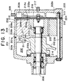
- the fixed-capacity single-ended swash plate compressor shown in Figure 13 is a known example of such a swash plate compressor.
- the outer shell 201 of the compressor is formed by joining a front housing 201b to the front end of a cylinder block 201a, forming a swash plate chamber 202 within.
- a cylinder cover 203 functioning as a rear housing having a discharge chamber 203a and an intake chamber 203b therein is joined to the rear end of the cylinder block 201a by means of a valve plate 204.
- An intake port 205 for receiving intake gas from an external refrigerant circuit (not shown) is disposed in a side wall of the cylinder cover 203 and is connected to the intake chamber 203b.
- a drive shaft 206 is disposed in a central portion of the outer shell 201 of the compressor and is rotatably supported by radial bearings 207.
- a plurality of cylinder bores 208 are formed in the cylinder block 201a parallel to the drive shaft 206 and equidistantly spaced in a circle of fixed circumference centered on the drive shaft 206. Consequently, a cylinder assembly is formed by the cylinder block 201a.
- Piston assemblies 209 each comprise a piston rod 209b and a single-headed piston 209a formed on the rear end of the piston rod 209b.
- a single-headed piston 209a is housed within each of the cylinder bores 208 so as to be flee to slide and reciprocate.
- a swash plate 210 is secured to the drive shaft 206 within the swash plate chamber 202 so as to rotate together with the drive shaft 206, the pistons 209a being engaged by the swash plate 210 by means of shoes 211. Furthermore, a thrust bearing 214 is disposed at the front end of a boss portion 210a of the swash plate 210, that is to say, between the boss portion 210a and the front housing 201b, thrust loads acting on the swash plate 210 being supported by the thrust bearing 214.
- Discharge holes 204a connecting each of the cylinder bores 208 to the discharge chamber 203a and intake holes 204b connecting each of the cylinder bores 208 to the intake chamber 203b are disposed in the valve plate 204.
- An intake valve-forming plate 212 integrally formed with a plurality of intake valves 212a for controlling the opening and closing of each of the intake holes 204b is interposed between the valve plate 204 and the cylinder block 201a
- a discharge valve-forming plate 213 integrally formed with a plurality of discharge valves 213a for controlling the opening and closing of each of the discharge holes 204a is interposed between the valve plate 204 and the cylinder cover 203.
- Gas passages 215 are disposed in the cylinder block 201a in the spaces between the plurality of cylinder bores 208, the swash chamber 202 being connected to the intake chamber 203b by means of the gas passages 215, so that blowback gas flowing into the swash chamber 202 during the process of compression by the pistons 209a is expelled to the intake chamber 203b.
- 216 is a retainer
- 217 is a discharge port
- 218 is a bolt joining the cylinder block 201a, the front housing 201b, and the cylinder cover 203 together.
- intake gas is directed from the external refrigerant circuit through the intake port 205 into the intake chamber 203b. Then, the refrigerant gas is taken from the intake chamber 203b through the intake holes 204b and intake valves 212a into the cylinder bores 208 and is compressed by the pistons 209a. The compressed refrigerant gas is expelled through the discharge holes 204a and the discharge valves 213a to the discharge chamber 203a and is discharged through the discharge port 217 to the external refrigerant circuit.
- the front ends of the pistons 209a (left side in figure) are exposed to the swash chamber which is at intake pressure, and at the same time the rear ends of the pistons 209a are exposed to the cylinder bores 208 which are filled with compressed refrigerant gas,
- the internal pressure (intake pressure) of the swash chamber 202 acts on the front end surface of each of the pistons 209a
- the internal pressure of the cylinder bores 208 acts on the rear end surface of each of the pistons 209a.
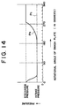
- Figure 14 is a graph explaining the conditions in one piston and shows the changes in the internal pressure Pc in the swash plate chamber 202 and the changes in the internal pressure Pb in the cylinder bore 208 relative to the rotational angle of the swash plate 210 (in degrees).
- the internal pressure Pc in the swash plate chamber 202 always remains at a practically constant low pressure, that is at the intake pressure, but the internal pressure Pb in the cylinder bore 208 fluctuates periodically between a low intake pressure and a high discharge pressure depending on the rotational angle of the swash plate 210.
- thrust loads from the front end towards the rear end act on the front end surfaces of the pistons 209a, and thrust loads from the rear end towards the front end act on the rear end surfaces of the pistons 209a.
- the thrust load acting on the thrust bearing 214 is given by the sum of these loads acting on the pistons 209a.
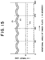
- Figure 15 is a graph explaining the axial load, and the vertical axis shows the thrust load, the direction from the rear end towards the front end being taken as positive.
- the number of pistons 209a has been taken to be six and the loads acting on all six pistons have been totalled.
- Ff indicates the thrust load acting from the front end towards the rear end due to the internal pressure in the swash chamber 202.
- Fr indicates the thrust load acting from the rear end towards the front end due to the internal pressure in the cylinder bores 208.
- Ft indicates the total load resulting from Ff and Fr. Since Ft is the sum of all of the loads acting on a plurality of pistons (in this case six), the amplitudes and periods of the fluctuations are small compared to those of the internal pressure in the single cylinder bore 208 shown in Figure 14.
- the present invention aims to solve the above problems and an object of the present invention is to provide a single-ended swash plate compressor which reduces the load acting on the thrust bearing, and suppresses shortening of the working life of the thrust bearing and increases in the size of the thrust bearing.
- a single-ended swash plate compressor having a means of substantially balancing the thrust load acting on the pistons in both axial directions by adjusting the pressure of the refrigerant acting in a direction opposite to the thrust load directed towards the front end due to internal pressure in the cylinder bores acting on the pistons.
- a single-ended swash plate compressor having an adjustment means for adjusting the internal pressure of the swash plate chamber acting on the front end surface of the pistons to an intermediate pressure between the intake pressure and the discharge pressure, whereby the thrust load directed towards the front end due to internal pressure in the cylinder bores acting on the pistons and the thrust load directed towards the rear end due to the internal pressure of the swash plate chamber are practically balanced.
- the thrust load fluctuates in both axial directions, but according to Claim 2 of the present invention, the thrust load fluctuating in both axial directions can be supported by the provision of thrust bearings at both the front end and the rear end of the swash plate.
- the internal pressure in the swash plate chamber can be set at any desired intermediate pressure suitable to the working conditions, such as the refrigerant used, the specifications of the compressor, the operating environment, etc.
- the single-ended swash plate compressor according to Claim 6 of the present invention is constructed such that cylinder bores are formed in both the front end and the rear end, and a compression action is performed in the cylinder bores at one end by pistons housed within the cylinder bores at that end, and a guide action is performed in the cylinder bores at the other end by pistons housed within the cylinder bores at that other end, whereby pressure is introduced into the cylinder bores in the guide end to cancel the reactive forces due to compression acting on the pistons in the compression end.
- the single-ended swash plate compressor according to Claim 7 of the present invention is constructed such that discharge pressure is introduced into some of the cylinder bores in the guide end, enabling the thrust loads in both axial directions to be balanced by a simple construction.
- piston rings are mounted on the outer circumferential sliding surfaces of the pistons housed in the cylinder bores in the guide end into which discharge pressure is introduced, whereby the blowback of gas from those cylinder bores to the swash plate chamber can be reduced.
- the diameter of the cylinder bores in the guide end is made smaller than the diameter of the cylinder bores in the compression end and discharge pressure is introduced into each of these cylinders in the guide end, whereby the thrust loads in both axial directions can be balanced by the ratio between the area of the piston assemblies subjected to the pressure of the cylinder bores in the guide end and the area of the piston assemblies subjected to the pressure of the cylinder bores in the compression end.
- FIG. 1 is a cross-section similar to that of Figure 13 for the conventional example above and shows a single-ended swash plate compressor according to the present invention which uses carbon dioxide as a refrigerant.
- the outer shell 1 of the compressor is formed by joining a front housing 1b to the front end of a cylinder block 1a. The joining thereof forms a swash plate chamber 2 within the outer shell 1.
- a cylinder cover 3 functioning as a rear housing formed with a discharge chamber 3a in a central region and an intake chamber 3b in a peripheral portion is joined to the rear end of the cylinder block 1a by means of a valve plate 4.
- a drive shaft 6 is inserted into an axial center portion of the cylinder block 1a and the other end passes through an axial center portion of the front housing 1b and extends outside, the drive shaft 6 being rotatably supported by radial bearings 7 disposed in the cylinder block 1a and the front housing 1b, respectively.
- a plurality of cylinder bores 8 are formed in the cylinder block 1a parallel to the drive shaft 6 and equidistantly spaced in a circle of fixed circumference centered on the drive shaft 6, and a single-headed piston 9a is housed within each of these cylinder bores 8 so as to be free to slide and reciprocate.
- 9 represents piston assemblies each comprising a piston rod 9b and a piston 9a formed on the rear end of the piston rod 9b.
- a cylinder assembly is constituted by the cylinder block 1a formed in this manner.
- a swash plate 10 is secured to the drive shaft 6 within the swash plate chamber 2 so as to rotate together with the drive shaft 6.
- the pistons 9a are engaged by the swash plate 10 by means of shoes 11.
- thrust bearings 14 are disposed at both the front end and the rear end of a boss portion 10a of the swash plate 10, that is to say, between the boss portion 10a and the front housing 1b and between the boss portion 10a and the cylinder block 1a, thrust loads acting on the swash plate 10 being supported by the thrust bearings 14.
- Discharge holes 4a connecting each of the cylinder bores 8 to the discharge chamber 3a and intake holes 4b connecting each of the cylinder bores 8 to the intake chamber 3b are disposed in the valve plate 4.
- An intake valve-forming plate 12 integrally formed with a plurality of intake valves 12a for controlling the opening and closing of each of the intake holes 4b is interposed between the valve plate 4 and the cylinder block 1a
- a discharge valve-forming plate 13 integrally formed with a plurality of discharge valves 13a for controlling the opening and closing of each of the discharge holes 4a is interposed between the valve plate 4 and the cylinder cover 3.
- a retainer 16 for controlling the opening angle of the discharge valves 13a is disposed in a central portion of the discharge chamber 3a in contact with the discharge valve-forming plate 13.
- a discharge port 17 connected to the external refrigerant circuit is disposed in the central portion of the cylinder cover 3 forming the discharge chamber 3a.
- 18 is a bolt joining the cylinder block 1a, the front housing 1b, and the cylinder cover 3 together.
- the adjustment means for adjusting the internal pressure of the swash plate chamber 2 to an intermediate pressure between the intake pressure and the discharge pressure is an adjustment valve 20 described below and is disposed and constructed in the manner described below.
- An adjustment valve accommodating hole 21 is formed in the cylinder block 1a, and a control passage 22 connecting the accommodating hole 21 to the intake chamber 3b is formed so as to pass through the valve plate 4, the intake valve-forming plate 12, and the discharge valve-forming plate 13.
- the adjustment valve 20 is accommodated within the accommodating hole 21 so as to be able to open and dose the connection between the swash plate chamber 2 and the intake chamber 3b.
- the adjustment valve 20 comprises: a securing portion 20a screwed into the portion of the accommodating hole 21 opening onto the swash plate chamber side; a case 20b forming a pressure sensing chamber 20c within; a bellows 20d functioning as a pressure sensing portion disposed within the pressure sensing chamber 20c; and a valve body 20e which opens and closes a port 20h by opening and closing a valve seat 20g in response to the contraction and expansion of the bellows 20d.
- a connecting passage 20f for introducing the pressure of the swash plate chamber 2 into the pressure sensing chamber 20c is formed in the securing portion 20a, the bellows 20d expanding and contracting in response to changes in pressure in the swash plate chamber 2.
- 20i is an adjustor portion for modifying the set pressure of the bellows 20d by adjusting the position thereof relative to the securing portion 20a, the set pressure in Embodiment 1 being adjusted to a suitable intermediate pressure between the intake pressure and the discharge pressure.
- the adjustment valve 20 when the adjustment valve 20 is closed, the internal pressure of the swash plate chamber 2 gradually increases.
- the internal pressure of the swash plate chamber 2 is introduced into the pressure sensing chamber 20c by means of the connecting passage 20f, and when the internal pressure of the swash plate chamber 2 rises above the predetermined intermediate pressure due to blowback gas, the bellows 20d contracts in response thereto as shown in Figure 2. Consequently, the valve body 20e opens the port 20h, and pressure from the swash plate chamber 2 is released through the port 20h and the control passage 22 to the intake chamber 3b until the pressure decreases to the predetermined intermediate pressure.
- the swash plate chamber 2 is maintained at the predetermined intermediate pressure during operation, and the intermediate pressure acts on the front end surfaces of the pistons 9a.
- the fluctuating internal pressure in the cylinder bores 8 acts on the rear end surfaces of the pistons 9a.
- Figure 3 shows the thrust load when the intermediate pressure is adjusted so that x is 0.33.
- This graph shows a case where there are six pistons 9a, Ff1 representing the thrust load acting from the front end towards the rear end, Fr1 representing the thrust load acting from the rear end towards the front end, and Ft1 representing the sum of both thrust loads (total load).
- Ff1 and Fr1 are practically balanced, Ft1 fluctuates only slightly in either axial direction.
- the thrust bearings 14 are not subjected to a large load. Furthermore, because the thrust bearings 14 are disposed at both the front end and the rear end of the swash plate 10, the total thrust load can be supported even if it fluctuates in both axial directions. As a result, the durability of the thrust bearings 14 is improved, and furthermore, because there is no need to use large thrust bearings, a contribution can be made to reducing the size of the compressor.
- the amount of gas moving from the bores 8a in the compression stage into the swash plate chamber 2 is balanced by the amount of gas moving from the swash plate chamber 2 into the bores 8b in the intake stage, and consequently the pressure of the swash plate chamber 2 is maintained at a predetermined intermediate pressure.
- Embodiment 2 embodying the swash plate compressor of the present invention will be explained using Figures 5 to 8.
- the single-ended swash plate compressor according to Embodiment 2 has pistons in both the front end and the rear end, the pistons in one end only performing the compression action and the pistons in the other end performing only a guide action.
- Figure 5 is a longitudinal section of this single-ended swash plate compressor, and in this figure, the cylinder assembly 101 is formed by joining a front cylinder block 101a and a rear cylinder block 101b. A space is formed in the center of the cylinder assembly 101 between the cylinder blocks 101a, 101b when the cylinder block 1a is joined to the cylinder block 1b, and this space constitutes a swash plate chamber 107.
- the swash plate chamber 107 connects to an intake passage (not shown) which is connected to an inlet 121.
- Drive shaft openings 103a, 103b are formed in the center of the cylinder blocks 101a, 101b, respectively.
- a drive shaft 105 is disposed in the center of the cylinder assembly 101 and is rotatably supported by radial bearings 104, which are disposed in the drive shaft openings 103a, 103b.
- a swash plate 108 is disposed in the swash plate chamber 107 so as to be rotatable by the drive shaft 105, the boss portion of the swash plate 108 being fitted over and secured to the center of the drive shaft 105.
- Thrust bearings 112 are disposed between both the front end and the rear end of the boss portion of the swash plate 108 and the central inside end surfaces of the cylinder blocks 101a, 101b to support the load in both axial directions of the swash plate 108.
- Six cylinder bores 109a, 109b are disposed equidistantly in a circle of prescribed radius around the drive shaft 105 in each of the cylinder blocks 101a, 101b.
- the cylinder bores 109a in the front cylinder block 101a and the cylinder bores 109b in the rear cylinder block 101b are disposed so as to form six pairs of cylinder bores, each pair having the same axial center.
- the cylinder bores 109a in the front end are used as guides, and the cylinder bores 109b in the rear end are used for compression.
- Piston assemblies 110 each comprise: a piston rod 110a; a guide piston 110b formed on the front end of the piston rod 110a; and a compression piston 110c formed on the rear end of the piston rod 110a.
- the piston assemblies 110 are disposed such that each of the guide pistons 110b is housed in a cylinder bore 109a in the front end, and each of the compression pistons 110c is housed in a cylinder bore 109b in the rear end.
- a swash plate engaging portion 110d with a portal-shaped cross-section in the axial direction is formed in the center of each of the piston rods 110a and shoes 111 are engaged by these swash plate engaging portions 110d.
- the piston assemblies 110 are constructed so as to be engaged by the surface 108a of the swash plate 108 by means of these shoes 111 and to be reciprocated as the swash plate 108 rotates.
- the front end surface of the cylinder assembly 101 constructed as described above is covered by a front housing 150 forming an outer shell.
- the rear end surface of the cylinder assembly 101 is covered by a rear housing 115 functioning as a cylinder cover by means of a valve plate assembly 116.
- These housings 150, 115 are joined and secured to the cylinder assembly 101 by means of a plurality of bolts 138.
- 138a are bolt holes for leading the bolts 138 from the front housing 150 to the valve plate assembly 116.
- the front housing 150 is joined to the front end surface of the cylinder assembly 101 by means of a gasket 150a, two intake pressure chambers 151 and two discharge pressure chambers 152 being formed therein as shown in Figure 6.
- the intake pressure chambers 151 are each formed in an oval shape so as to connect two cylinder bores 109a, and are disposed on the left and right in Figure 6. Furthermore, the intake pressure chambers 151 are connected to the swash plate chamber 107 by connecting passages 156 which pass through the length of the front end cylinder block 101a.
- the discharge pressure chambers 152 are positioned over the two cylinder bores 109a lying between the intake pressure chambers 151, and form an approximately cylindrical space with a diameter approximately equal to that of the two cylinder bores 109a. Furthermore, the discharge pressure chambers 152 are each connected to one of the bolt holes 138a formed around the bolts 138 by connecting grooves 153 cut into the end surface of the cylinder assembly 101 of the front housing 150.
- the interior of the rear housing 115 is divided into two concentric spaces by a partition.
- the inner of these divided spaces is connected to the swash plate chamber 107 by means of a plurality of connecting passages 127 formed in the cylinder block 101b, forming an intake chamber 131.
- the intake chamber 131 is connected to the rear cylinder bores 109b by means of intake ports 133 and intake valves 132 described below.
- the outer of the spaces within the rear housing 115 forms a discharge chamber 134 connected to each of the cylinder bores 109b by means of discharge ports 136 and discharge valves 135 described below.
- the discharge chamber 134 is connected to a discharge outlet 122 by means of a discharge passage 124.
- the valve plate assembly 116 is formed by disposing an intake valve-forming plate 116A, a valve plate 116B, a discharge valve-forming plate 116C, and a retainer gasket 116D in order from the cylinder assembly 101 side, and is held between the cylinder assembly 101 and the cylinder cover 115.
- the valve plate 116B is perforated by a plurality of intake ports 133 connecting the intake chamber 131 to each of the cylinder bores 109b, and a plurality of discharge ports 136 connecting the discharge chamber 134 to each of the cylinder bores 109b.
- the intake valve-forming plate 116A is integrally formed with a plurality of intake valves 132 for individually controlling the opening and closing of each of the intake ports 133.
- the discharge valve-forming plate 116C is integrally formed with a plurality of discharge valves 135 for individually controlling the opening and closing of each of the discharge ports 136.
- the retainer gasket 116D is integrally formed with a plurality of retainers for individually regulating the opening angle of each of the discharge valves 135.
- Figure 8 is a graph showing the thrust loads acting on a six-piston assembly 110 due to such pressure conditions, Ff2 representing the thrust load acting from the front end towards the rear end, Fr2 representing the thrust load acting from the rear end towards the front end, and Ft2 representing the total load being the sum of these thrust Loads Ff2 and Fr2.
- Ff2 representing the thrust load acting from the front end towards the rear end
- Fr2 representing the thrust load acting from the rear end towards the front end
- Ft2 representing the total load being the sum of these thrust Loads Ff2 and Fr2.
- the thrust load acting from the front end towards the rear end Ff2 and the thrust load acting from the rear end towards the front end Fr2 are practically balanced and the sum of these two thrust loads (total load) Ft2 fluctuates only slightly in either axial direction, exhibiting no great imbalances in load. Consequently, this total load Ft2 shows the same magnitude and variance as the total thrust load Ft1 in Embodiment 1 above.
- the two cylinder bores 109a in the front end whose internal pressure is discharge pressure and the four cylinder bores 109a in the front end whose internal pressure is intake pressure are disposed symmetrically about the axial center of the drive shaft, the moments about the center of the swash plate due to the thrust loads acting on each of the pistons are in a mutually cancelling relationship, reducing deformation of the drive shaft 105 and load on the radial bearings 104.
- piston rings 110e are mounted on the outer circumferential surfaces of the two pistons in which the internal pressure of the cylinder bores 109a is discharge pressure, blowback gas from these cylinder bores 109a to the swash plate chambers 107 is reduced, improving compression efficiency.
- Embodiment 3 will be explained on the basis of Figures 9 to 11. Moreover, since Embodiment 3 has many points in common with Embodiment 2 above, identical structural elements will be given identical reference numerals and explanations thereof will be simplified.
- Embodiment 3 has six pairs of cylinder bores 109a, 109b, the difference being that in Embodiment 3 discharge pressure is introduced into every second cylinder bore 109a.
- Figure 9 is a cross-section similar to that of Figure 5 for Embodiment 2 above, but the section is taken along a line passing through two cylinder bores positioned symmetrically relative to the center of the drive shaft (line IX - IX in Figure 10).
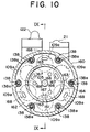
- Figure 10 is a cross-section of a front housing 160 taken along line X - X in Figure 9.
- a front housing 160 is joined to the front end surface of the cylinder assembly 101 by means of a plate 165 so as to cover the cylinder assembly 101.
- Gaskets 160a, 160b are disposed between the plate 165 and the front housing 160, and between the plate 165 and the cylinder assembly 101, respectively, so as to seal the joints.
- the interior of the front housing 160 is divided into two concentric chambers by a partition 164 formed integrally with the front housing 160 so as to protrude inwards from the end wall thereof, the inner chamber forming an intake pressure chamber 161 and the outer chamber forming a discharge pressure chamber 162.
- the intake pressure chamber 161 is connected to the swash plate chamber 107 by connecting passages 166 (see Figure 10) running the length of the front end cylinder bores 109a. Furthermore, the intake pressure chamber 161 is constantly connected to three alternately-positioned cylinder bores 109a by intake gas passage holes 167 disposed in the plate 165. Consequently, intake pressure is constantly introduced into these cylinder bores 109a during operation.
- Three connecting grooves 163 (see Figure 10) connecting the bolt holes 138a to the discharge pressure chamber 162 are cut into the end surface of the front housing 160. As in the case of Embodiment 2, these bolt holes 138a are connected to the discharge chamber 134 within the cylinder cover 115.
- the remaining cylinder bores 109a other than the cylinder bores connected to the intake pressure chamber 161 are constantly connected to the discharge pressure chamber 162 by discharge gas passage holes 168 disposed in the plate 165. Consequently, discharge pressure is constantly introduced into these cylinder bores 109a during operation.
- the intake gas passage holes 167 and the discharge gas passage holes 168 are formed sufficiently large so that no compression action occurs within the guide end cylinder bores 109a.
- Figure 11 is a graph showing the total load Ft3 being the sum of the thrust loads acting on a six-piston assembly 110 in both axial directions, showing the total load Ft2 acting in the case of Embodiment 2 and the thrust load Ft acting in the case of the conventional example for comparison.
- carbon dioxide has been used as the refrigerant. Consequently, it can be seen that when the refrigerant is carbon dioxide, introduction of discharge gas into two of the cylinder bores 109a, as in Embodiment 2, gives the best balance of thrust loads.
- Embodiment 3 is still an improvement over the conventional technique.
- the present embodiment may be preferable depending on the type of refrigerant.
- the present embodiment is preferable because it is more evenly balanced in all directions.
- Embodiment 4 will be explained on the basis of Figure 12. Moreover, since Embodiment 4 has many points in common with Embodiments 2 and 3 above, structural elements identical to those in Embodiments 2 and 3 will be given identical reference numerals and explanations thereof will be simplified.
- Embodiment 4 has six pairs of cylinder bores 109a, 109b, the difference being that in Embodiment 4 the diameter of the front end cylinder bores 109a is made smaller than the diameter of the rear end cylinder bores 109b, and the cross-sectional area of the guide pistons is made smaller than that of the compression pistons, and in addition, discharge pressure is introduced into all of the front end cylinder bores 109a.
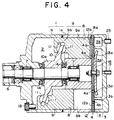
- Figure 12 is a cross-section similar to that of Figure 5 for Embodiment 2 above.
- a front housing 170 is connected to the front end surface of the cylinder assembly 101.
- the interior of the front housing 170 is formed into a single chamber functioning as a discharge pressure chamber 172.
- the construction for introducing discharge gas to the discharge pressure chamber 172 is similar to that in Embodiment 2 and is achieved by connecting the discharge pressure chamber 172 to the bolt holes 138a by means of connecting grooves 173 cut into the end surface of the front housing 170 and connecting the bolt holes 138a to the discharge chamber 134 in the cylinder cover 115.
- the balance of thrust loads can be variously altered by changing the cross-sectional area of the guide pistons 110b. Consequently, the acting thrust loads and the balance of thrust loads in both axial directions may change depending on the refrigerant, but the balance of thrust loads in both axial directions can be adjusted by means of the designed cross-sectional area of the pistons 110b, 110c.
- Embodiment 4 the reduction of the size of the guide pistons 110b as in Embodiment 4 can also be applied to Embodiments 2 and 3 above.
- a single-ended swash plate compressor In a single-ended swash plate compressor, unbalanced thrust loads in either axial direction are reduced so that thrust loads acting on pistons in the direction of the front end are practically balanced by those in the direction of the rear end, for example, by connecting an intake chamber to a swash plate chamber by means of an adjustment valve to adjust the pressure in the swash plate chamber acting on the front end surfaces of the pistons to a suitable intermediate pressure by the action of the adjustment valve.
- discharge pressure is introduced into some of the cylinder bores housing guide pistons and intake pressure is introduced into the cylinder bores housing guide pistons into which discharge pressure is not introduced.
Landscapes
- Engineering & Computer Science (AREA)
- Mechanical Engineering (AREA)
- General Engineering & Computer Science (AREA)
- Compressors, Vaccum Pumps And Other Relevant Systems (AREA)
Applications Claiming Priority (4)
| Application Number | Priority Date | Filing Date | Title |
|---|---|---|---|
| JP10056987A JPH11257219A (ja) | 1998-03-09 | 1998-03-09 | 片側斜板式圧縮機 |
| JP5698798 | 1998-03-09 | ||
| JP5849298 | 1998-03-10 | ||
| JP10058492A JPH11257221A (ja) | 1998-03-10 | 1998-03-10 | 片側斜板式圧縮機 |
Publications (2)
| Publication Number | Publication Date |
|---|---|
| EP0942169A2 true EP0942169A2 (de) | 1999-09-15 |
| EP0942169A3 EP0942169A3 (de) | 2000-02-23 |
Family
ID=26397994
Family Applications (1)
| Application Number | Title | Priority Date | Filing Date |
|---|---|---|---|
| EP99104605A Withdrawn EP0942169A3 (de) | 1998-03-09 | 1999-03-08 | Kurbelkammerdruckregelung für einen Schrägscheibenverdichter |
Country Status (2)
| Country | Link |
|---|---|
| US (1) | US6280151B1 (de) |
| EP (1) | EP0942169A3 (de) |
Cited By (2)
| Publication number | Priority date | Publication date | Assignee | Title |
|---|---|---|---|---|
| US6565329B2 (en) | 2000-01-11 | 2003-05-20 | Kabushiki Kaisha Toyoda Jidoshokki Seisakusho | Electric type swash plate compressor |
| EP1150012A3 (de) * | 2000-04-28 | 2004-02-11 | Kabushiki Kaisha Toyota Jidoshokki | Taumelscheibenverdichter variabler Verdrängung |
Families Citing this family (3)
| Publication number | Priority date | Publication date | Assignee | Title |
|---|---|---|---|---|
| EP1136700A4 (de) * | 1999-10-04 | 2005-04-27 | Toyota Jidoshokki Kk | Elektrischer kompressor |
| JP2001193638A (ja) * | 2000-01-11 | 2001-07-17 | Toyota Autom Loom Works Ltd | 多段式ピストン圧縮機 |
| US20060147330A1 (en) * | 2002-12-26 | 2006-07-06 | Zexel Valeo Climate Control Corporation | Gasket for compressor |
Family Cites Families (6)
| Publication number | Priority date | Publication date | Assignee | Title |
|---|---|---|---|---|
| JPH0235983U (de) | 1988-08-26 | 1990-03-08 | ||
| KR950003623A (ko) | 1993-07-19 | 1995-02-17 | 이소가이 찌세이 | 왕복 운동형 압축기에 있어서의 회전축의 지지구조물 |
| JPH08170588A (ja) * | 1994-12-16 | 1996-07-02 | Toyota Autom Loom Works Ltd | 往復動型圧縮機 |
| CH689826A5 (de) | 1995-05-10 | 1999-12-15 | Daimler Benz Ag | Fahrzeug-Klimaanlage. |
| JPH10169558A (ja) * | 1996-12-09 | 1998-06-23 | Toyota Autom Loom Works Ltd | 片頭ピストン式圧縮機 |
| JPH10253177A (ja) | 1997-03-12 | 1998-09-25 | Zexel Corp | 遷臨界冷凍サイクル用圧縮機 |
-
1999
- 1999-03-04 US US09/262,599 patent/US6280151B1/en not_active Expired - Fee Related
- 1999-03-08 EP EP99104605A patent/EP0942169A3/de not_active Withdrawn
Non-Patent Citations (1)
| Title |
|---|
| None |
Cited By (2)
| Publication number | Priority date | Publication date | Assignee | Title |
|---|---|---|---|---|
| US6565329B2 (en) | 2000-01-11 | 2003-05-20 | Kabushiki Kaisha Toyoda Jidoshokki Seisakusho | Electric type swash plate compressor |
| EP1150012A3 (de) * | 2000-04-28 | 2004-02-11 | Kabushiki Kaisha Toyota Jidoshokki | Taumelscheibenverdichter variabler Verdrängung |
Also Published As
| Publication number | Publication date |
|---|---|
| EP0942169A3 (de) | 2000-02-23 |
| US20010019698A1 (en) | 2001-09-06 |
| US6280151B1 (en) | 2001-08-28 |
Similar Documents
| Publication | Publication Date | Title |
|---|---|---|
| US6038960A (en) | Reciprocating pistons of piston-type compressor | |
| US5921756A (en) | Swash plate compressor including double-headed pistons having piston sections with different cross-sectional areas | |
| US6379123B1 (en) | Capacity control scroll compressor | |
| US5645405A (en) | Reciprocating type compressor with muffling chambers | |
| EP0410453B1 (de) | Schmiervorrichtung für eine Kolbenanordnung in einem Schiefscheibenverdichter | |
| US6134898A (en) | Positive-displacement-type refrigerant compressor with a novel oil-separating and lubricating system | |
| AU646188B2 (en) | Slant plate type compressor with variable displacement mechanism | |
| US5533871A (en) | Single-headed-piston-type swash-plate compressor having pulsation damping system | |
| US6322086B1 (en) | Seal structure of compressor, and the compressor | |
| US5074768A (en) | Piston compressor | |
| US5562425A (en) | Gas suction structure in piston type compressor | |
| US6382927B1 (en) | Valve plate assembly positioning structure for compressor | |
| US5419685A (en) | Reciprocating-piston-type refrigerant compressor with a rotary-type suction-valve mechanism | |
| EP0595313B1 (de) | Auslassventilvorrichtung eines Kältemittelverdichters | |
| US5372483A (en) | Axial multi-piston type compressor having rotary valve for introducing fluid from suction chamber into cylinder bores | |
| EP0942169A2 (de) | Kurbelkammerdruckregelung für einen Schrägscheibenverdichter | |
| US5704769A (en) | Noise suppressing mechanism in piston-type compressor | |
| US5401144A (en) | Swash plate type refrigerant compressor | |
| US5380163A (en) | Gas guiding mechanism in a piston type compressor | |
| EP0499343A2 (de) | Taumelscheibenkompressor | |
| US5533872A (en) | Reciprocating piston compressor | |
| US6508633B2 (en) | Swash plate type compressor of variable capacity type | |
| JP2001027177A (ja) | 可変容量型斜板式圧縮機 | |
| US5536149A (en) | Support structure for rotary shaft of compressor | |
| US5368450A (en) | Swash plate type compressor |
Legal Events
| Date | Code | Title | Description |
|---|---|---|---|
| PUAI | Public reference made under article 153(3) epc to a published international application that has entered the european phase |
Free format text: ORIGINAL CODE: 0009012 |
|
| AK | Designated contracting states |
Kind code of ref document: A2 Designated state(s): DE FR IT |
|
| AX | Request for extension of the european patent |
Free format text: AL;LT;LV;MK;RO;SI |
|
| PUAL | Search report despatched |
Free format text: ORIGINAL CODE: 0009013 |
|
| AK | Designated contracting states |
Kind code of ref document: A3 Designated state(s): AT BE CH CY DE DK ES FI FR GB GR IE IT LI LU MC NL PT SE |
|
| AX | Request for extension of the european patent |
Free format text: AL;LT;LV;MK;RO;SI |
|
| 17P | Request for examination filed |
Effective date: 20000822 |
|
| AKX | Designation fees paid |
Free format text: DE FR IT |
|
| RAP1 | Party data changed (applicant data changed or rights of an application transferred) |
Owner name: KABUSHIKI KAISHA TOYOTA JIDOSHOKKI |
|
| STAA | Information on the status of an ep patent application or granted ep patent |
Free format text: STATUS: THE APPLICATION IS DEEMED TO BE WITHDRAWN |
|
| 18D | Application deemed to be withdrawn |
Effective date: 20041001 |